取扱説明書
No.99MAL108B4
U-WAVE-T
はじめに
U-WAVE-T(以下本器という)は、デジマチック出力付き測定器に、接続ケーブルを使用して接続し、
弊社製 U-WAVE-R(別売)に測定値を無線通信する装置です。
本器には「IP67 タイプ」と「ブザータイプ」の 2 機種があります。
本器の性能を十分に発揮させ、長期にわたり良好な状態でご使用いただくために、ご使用の前には
この取扱説明書をよくお読みいただき、正しくお使いください。
本書はお読みになった後も大切に保管してください。
本器の仕様及び本書の内容は将来予告なしに変更することがあります。
安全に関するご注意
商品のご使用に当たっては、記載の仕様・機能・使用上の注意に従ってご使用ください。
それ以外でご使用になりますと安全性を損なう恐れがあります。
・ 電波により誤動作を引き起こす可能性のある医療機器の近くでは使用しないでください。
・ 本器は、電波を使用しており、電波の到達距離範囲内であっても外来ノイズ等の影響で
警告
等の影響で通信が途切れる可能性があります。その際の損害防止処置(安全対策)を十分
に行ってください。
・ 本器が万一故障した場合の損害防止処置(安全対策)を十分に行ってください。
・ 電池を分解、ショート、充電、加熱などしないでください。内容物が漏れて目に入ったり、
発熱、破裂の原因となります。
・ 本器に使用している電池の内部には、刺激性物質が含まれています。万一その液状の
内容物が誤って目や皮膚などに付着した場合、きれいな水で洗い流してください。
・ 万一電池を飲み込んだ場合には、直ちに口内を洗浄し大量の水を飲ませて吐き出させた
後、いずれの場合にも医者に相談してください。
海外移転に関するご注意
警告
以下の行為、状況は本器の故障、誤動作の原因となりますのでご注意ください。
重要
・ 落下などの急激なショックを与えたり、過度の力を加えないでください。
・ 3 ヶ月以上ご使用にならない場合には、本器より電池を取り外して保管してください。
電池の液漏れで本器を破損する恐れがあります。
・ 直射日光のあたる場所、極端に熱い所、寒い所での使用、保管は避けてください。
・ 酸、アルカリなどの溶液や有機溶剤が付着する恐れがある場所での使用、保管は避けてください。
・ 電気ペン等の高電圧機器を使用した場合、電子部品が破壊される場合があります。
・ 接続ケーブルに無理な力をかけないよう、また無理な曲げを与えないよう注意してください。
・ 電池電圧が低下してきましたら、動作が不安定になる前に早めに電池交換をしてください。
保障
!
!
その他のご注意
本器は、「外国為替及び外国貿易法の輸出管理令別表第 1 若しくは外国為替令別表に
定める 16 の項」によるキャッチオール規制対象貨物又はプログラムです。また、本取扱
説明書も、キャッチオール規制対象技術です。製品の輸出や海外移転、非居住者への技術
の提供等にあたっては、経済産業省への輸出許可・役務取引許可申請や届出等が必要
となる場合がありますので、事前に弊社にご相談ください。
本器は、厳重な品質管理のもとで製造されていますが、お客様の正常な使用状態において、
万一お買い上げの日から 1 年以内に故障した場合には、無償で修理させていただきます。
お求めの代理店、あるいは弊社営業所へご連絡ください。
分別処理を行っている EU(欧州)諸国で電気・電子機器の廃棄をする際の注意
商品または包装に記されたこのシンボルマークは、EU 諸国でこの商品を廃棄する時に
一般家庭ゴミと一緒に捨てないようにするためのものです。WEEE(廃電気電子機器)を
土壌に埋め立てする量を減らし環境への影響を低減するために、商品の再利用と
リサイクルにご協力ください。処理方法に関する詳しい内容は、お近くのお買い上げに
なった小売店や代理店にお問い合わせください。
[1] 各部名称と寸法 (単位:mm)
1.LED 表示部(緑色、赤色、橙色)
4.デバイス ID ラベル
2.電池蓋
5.認証ラベル
3.コネクタカバー
6.ブザー穴(ブザータイプのみ)
4. デバイス ID ラベル
3. コネクタカバー
電波法に関するご注意
本器(IP67 タイプ、プザータイプ)は、日本・EU 加盟国・アメリカ・カナダでご使用になれます。
日本・EU 加盟国・アメリカ・カナダ以外でのご使用は法律で禁止されています。
!
警告
・ 本器は、電波を利用する為、使用する国において定められている該当規制に従って
ご使用ください。
・ 分解、改造をしないでください。法律で禁止されています。
・ 本器に添付されている認証ラベルは剥がさないようにしてください。
ラベルのないものは使用が禁止されています。
・ 航空機にご搭乗の際は、必ず本器から電池を取り外し、航空機内でご使用にならない
でください。航空機内での無線機器の使用は法律で禁止されています。
2. 電池蓋
6. ブザー穴
1. LED 表示部
(ブザータイプのみ)
5. 認証ラベル
(このラベルは、ご使用になるタイプで異なります。)
無線通信環境におけるご注意
本器の性能が、障害物などの環境により十分に発揮できない場合がありますのでご注意ください。
障害物の要因となる項目は下記をご参照ください。
1) 本器が通信できなくなる可能性がある場合
項目
内容
コンクリート壁
完全に遮断された状態での通信はできません。
金属性のパーテーションなど
通信速度が低下若しくは通信が遮断される可能性があります。
無線 LAN、ZigBee
通信速度が低下若しくは通信が遮断される可能性があります。
Bluetooth などの通信機器
本器と通信チャネル(バンド ID)及び設置距離をできる限り
及び電子レンジ
離してご使用ください。
放電加工機等の工作機械、搬送用クレーン、アーク溶接等が
工作機械など
稼動している作業現場では、通信速度の低下若しくは通信が
遮断される可能性があります。
2) 本器が周りの機器に影響を与える可能性がある場合
項目
内容
レーザメスやヘルスメータなどの医療機器の近くでは使用
医療機器
しないでください。
[2] 電池の交換
1) 電池のセット
出荷時には、電池がセットされておりませんので、以下の手順でセットしてください。ねじの
取り付け・取り外しは、必ず標準付属品の 0 サイズドライバ(No.05CZA619)を使用し、
5∼8N・cm 程度のトルクで締め付けてください。
(1) 0 サイズドライバで取り付けねじ(M2.5×0.45×3 / No.A115-2515C)を外します。
(2) 電池蓋を外します。
(3) 電池をプラス側が蓋側を向くように電池の端を本器の電池端子”+”に差し込み滑りこます
ようにして電池の反対側を本器の電池押さえ爪の中に挿入します。
(4) 所定の位置にパッキン(No.02AZD734)が正しく取付けられていることを確認してください。
(5) 電池蓋を取り付けます。
(6) 0 サイズドライバで取り付けねじを締め付けます。
(7) パッキンは取り外さないでください。
(1)、(6)
(3)
防塵防水性についてのご注意
IP67 タイプ U-WAVE-T の性能を発揮するために必ず以下の点をお守りください。
重要
・ 防塵防水性は接続ケーブルかん合時、また、電池蓋取付け時に保証されます。
ご使用にならないときは、水や油が浸入しないように、各蓋をして保管してください。
・ 水や塵に対する保護(IP67)を十分発揮されるためには、電池をセットする時に電池蓋をねじで
しっかり締めてください。またパッキンを取り外さないでください。
・ 接続ケーブルの被覆が破れると、毛細管現象により液体が本器内部および測定器内部へ侵入し
故障の原因となりますので、すみやかに交換しください。
・ 切粉、ごみなどにより各部のパッキンが破損しないように、十分注意の上ご使用ください。
万一パッキンが破損した場合は、防塵防水性が損なわれますのですみやかに交換または修理に
お出しください。
・ ゴムキャップや各シール部分に使用しているゴム等の材質は、多様化するクーラント、薬品などに
対して万能ではありません。これらが著しく劣化する場合には、最寄りの弊社営業所までご相談
ください。
・ 本器は各部にシールが施されているため、分解できない構造となっております。
そのため、分解されますと所定の性能を発揮できません。
・ 水没する場所では使用しないでください。クーラント等の侵入を防ぎ切れません。
参考
IP67保護等級 (詳細は IEC 60529 を参照してください)
・ 異物に対する保護(等級 6):塵埃の侵入に対する保護、完全な接触保護。
・ 水に対する保護(等級 7):最下端が水面から 1 mの位置に 30 分間の潜水状態で
水中に没しても有害な影響のないもの。
2) 電池の取り外し
取り外し時は、小型のマイナスドライバー等を電池押さえ爪と電池の間に差し込む等により、
“てこ”の要領で電池を取り出します。
3) 電池電圧低下警告
本器は、電池の電圧が低下すると LED 表示部が赤色に点滅し、電圧低下警告エラーを U-WAVE-R
に送信します。速やかに電池を交換してください。
(ブザータイプは、LED 点滅と共にブザー音でも警告します。)
また、本器の電源に使用している電池(CR2032)は、数秒間隔の頻度で、連続的に測定データの伝
送を行った場合、電池消耗末期に、急激に電池電圧の復帰が起こる特性があります。このような場
合には、電池電圧低下警告エラーを出力しないまま、徐々に、LED 表示が暗くなってきたり、ブザー
音が低くなってきますので、速やかに電池を交換してください。
重要
・ 電池は必ず CR2032(リチウム電池)をご使用ください。
・ お買い上げのとき付属されている電池は、機能や性能を確認するためのものです。所定の寿命
を満足しない場合があります。
・ CR2032 は、一度ご使用になった古い電池でも、電池を取り外して暫く放置すると電圧が高くなる
ことがあります。しかし古い電池はご使用できませんので必ず新しい電池をご使用ください。
・ 電池の廃棄にあたっては、条例、規制などに従ってください。
・ 電池の取り外し、取付け作業時には、電池端子が折れたり曲がらないように、無理な力が
掛からないように注意してください。特に折れた電池端子の破片が本器内に入ってしまいますと
故障の原因になります。
[7]仕様
[3] 接続ケーブルの取り付け
・ 電池挿入後、接続ケーブル(オプション:詳細は 8 項をご覧ください。)を本器に取り付けてください。
重要
接続ケーブル(02AZD790A、B)をご使用して、本器を取付ける際は、特にケーブルの向きをご注意
機種
コード No.
認証番号
ください。逆に接続するとデータ送信できません。
接続ケーブルの黒色側 ⇒ U-WAVE-T
保護等級
ブザーの有無
送信出力
通信距離
接続ケーブルの灰色側 ⇒ 測定器
DATA スイッチ
黒色
U-WAVE-T 側
測定器側
(ご使用になる測定器により形状と取り付け部の色が異なります。)
適合規格
IP67 タイプ
ブザータイプ
02AZD730D
02AZD880D
005WWCA0166(日本)
005WWCA0168(日本)
VXU-02AZD730D(アメリカ)
VXU-02AZD880D(アメリカ)
4396B-02AZD730D(カナダ)
4396B-02AZD880D(カナダ)
IP67
無
無
有
1 mW (0dBm) 以下
約 20 m(オフィス環境見通し)
日本 ARIB STD-T66
EN 50371:2002
欧州 EN 300 440-1 V1.3.1 and EN 300 440-2 V1.1.2
EN 301 489-01 V1.6.1 and EN 301 489-03 V1.4.1
アメリカ ・47 CFR Part 15.247:(Subpart :C) ・47 CFR Part 15,(Subpart :B)
・ 接続ケーブルは、以下の手順でセットしてください。
カナダ
・ ねじの取り付け・取り外しは、必ず標準付属品の 0 サイズドライバを使用し、5∼8N・cm 程度の
トルクで締め付けて下さい。
(1) 0 サイズドライバでコネクタカバー取付けねじ(M1.7×0.35×2.5 /No. A115-1712C)を外します。
(2) コネクタカバーを外します。
(3) 所定の位置にパッキン(No.09GAA374)が正しく取付けられていることを確認してください。
(4) 本器に接続ケーブルを取り付けてください。
(5) 接続ケーブルの端部を指で押さえ、蓋と本体とにすき間ができないようにして、接続ケーブル
取り付けねじで締め付けます。
(6) パッキンは取り外さないでください
(1)
(5)
無線規格
通信周波数
使用バンド
変調方式
無線通信速度
LED表示
電池
電池寿命
使用温度(湿度)
保存温度(湿度)
外形寸法
本体質量
・RSS-210 (Issue 7) and RSS-Gen (Issue 2) ・ICES 003 (Issue 4)
IEEE802.15.4 準拠
2.405∼2.475 GHz
15ch (5MHz 間隔)
DSSS (直接スペクトラム拡散)
250 kbps
緑/橙/赤 3 色表示
CR2032 (3 V):1 個
40 万回
0∼40 ℃(20∼80%RH、非結露)
-10∼60℃(20∼80%RH、非結露)
44×29.6×18.5 (mm)
約 23 g
○ 標準付属品
・ U-WAVE-T 取扱説明書(本書) No. 99MAL108B ・ 電池に関する注意 No. 99MAL111W
・ 0サイズドライバ No. 05CZA619 ・ リチウム電池 CR2032C(B)N ・ 保証書
○ オプション No.02AZD790A∼G 接続ケーブル 詳細は 8 項をご参照ください。
重要
パッキン(No.09GAA374)が外れた状態で無理に接続ケーブルを取り付けるとパッキンが破損し、
[8] 接続ケーブル
接続ケーブルは、ご使用する測定器にあったケーブルを選択する必要があります。
正しい接続ケーブルをご使用ください。
故障の原因になります。
[4] U-WAVE-R の設定情報の登録
本器は、電池を挿入し接続ケーブルの取り付け後、通信したい U-WAVE-R の設定情報を登録
します。登録方法及び登録内容の詳細は、U-WAVE-R 付属 CD の’PDF_Manual’フォルダ内の
「U-WAVEPAK ユーザーズマニュアル」をご参照ください。参照するためには Adobe 社の
パーツ No.
機種
02AZD790A
出力スイッチ付
防水タイプ
「Adobe Reader」が必要です。
重要
・ 情報登録は、測定器を取り付ける前に接続ケーブルのDATAスイッチで行ってください。
・ 設定した情報は、電池交換後も保持します。
02AZD790B
出力スイッチ付
防水タイプ
[5] 測定器への取り付け
・ 情報登録後、測定器に取り付けます。
・ 測定器へは付属のケーブルクランプ若しくはマジックテープ等をご準備頂き、測定に支障がなく、
本器の LED 表示が見やすいように取付けてください。
[6] 機能
1) 無線通信機能
02AZD790C
出力スイッチ付
本器は、DATAスイッチにより下記のような通信を行います。
通信内容
DATA スイッチ押し時間
LED
測定データ送信
2 秒以下押す
-
キャンセルコマンド送信
2 秒以上 5 秒未満押す
橙色 LED が 0.1 秒間隔で点滅
U-WAVE-R 検索実行
5 秒以上 10 秒未満押す
橙色 LED が 0.3 秒間隔で点滅
02AZD790D
平形(10 ピン)
注記
・ キャンセルコマンドとは、誤操作により誤った測定データを U-WAVE-R に送信した時、そのデータ
が誤りであることを報せるために送信するコマンドです。
・ U-WAVE-R 検索を実行すると本器の設定情報を登録している U-WAVE-R に接続します。
・ 10 秒以上、DATA スイッチを押していると、橙色 LED 点滅が終了し、何も機能しません。
本器は、LED(ブザー)により U-WAVE-R に正常に通信を行えたかどうかを確認できます。
但し、ブザーはブザータイプのみです。
内容
無線通信が正常に完了した
・ 無線通信が失敗した。
・ エラーが発生した。
LED
ブザー
緑色 LED が点滅
短く 2 回鳴る
赤色 LED が点滅
長く 1 回鳴る
02AZD790E
丸型(6 ピン)
2) 設定情報の初期化方法
本器をご使用している間に通信ができなくなった場合は、U-WAVE-R 取扱説明書内“トラブル
シューティング”をご覧ください。それでも通信ができなかった時、4 項で登録した設定情報を初期化
し、本器を工場出荷状態にして再度通信を試みてください。
下記の手順で初期化してください。
(1) ご使用の電池を取り外してください。取り外し方法は 2 項をご参照ください。
(2) 接続ケーブルのDATAスイッチを押したまま電池を再挿入してください。初期化されます。
02AZD790F
平形ストレート
(3) 電池カバーを再度取り付けて、セットアップを実行してください。
重要
一度、初期化をすると今まで使用していた設定情報がクリアされます。
株式会社ミツトヨ 神奈川県川崎市高津区坂戸 1-20-1
KAWASAKI, JAPAN
シリーズ No.
対応測定器
対応測定器
500
500
571
572
573
ABS クーラントプルーフキャリパ
スーパキャリパ
ABS クーラントプルーフデプスゲージ
ABS クーラントプルーフ測長ユニット
ABS クーラントプルーフ専用タイプ
293
293
--329
350
--468
クーラントプルーフマイクロメータ
クーラントプルーフマイクロメータ
クーラントプルーフ専用マイクロメータ
デジマチックマイクロデプスゲージ
クーラントプルーフマイクロメータヘッド
デジマチック専用マイクロメータ
デジマチックホールテスト
500
571
572
500
---
ABS デジマチックキャリパ
ABS デジマチックデプスゲージ
ABS デジマチック測長ユニット
ABS デジマチックキャリパ
ABS デジマチックキャリパ専用タイプ
178
179
515
518
519
542
543
544
544
572
574
164
227
227
293
--293
--339
337
468
515
568
810
810
192
500
511
543
543
550
551
552
570
547
572
574
575
811
サーフテスト
SJ-201/301/401/402
デジダーム
DGE
デジタルセラハイトマスタ
HMD-C
QM-Height
QMH-S
デジタルミューチェッカ
M
リニヤゲージカウンタ
EB/EC-D
デジマチックインジケータ
ID-H/ID-F
レーザスキャンマイクロメータ
LSM-9506
レーザスキャンマイクロメータ
LSM-6200/6900
(デジマチックコードアウトユニット(No. 02AGC840 使用時))
和差演算ユニット
SD-U1
ハイトマチック
HDF
デジマチックマイクロメータヘッド
MHD-M
デジマチックマイクロメータヘッド
CLM-MH
測定力可変式デジマチックマイクロメータ
CLM
クイックマイクロ
MDQ
専用クイックマイクロ
(符号の末尾が-QM)
デジマチックマイクロメータ
MDC-M
デジマチック専用マイクロメータ
(符号の末尾が-DM)
デジマチックつぎたしパイプ内側マイクロメータ
IMJ-M
デジマチックつぎたしロッド内側マイクロメータ
IMZ-M
デジマチックホールテスト
HTD
デジタルハイトマスタ
HME-DM
ABS ボアマチック
SBM-C
微小硬さ試験機
HM-100/200/HV-100/HH-411
ロックウェル硬さ試験機
HR-500
デジマチックハイトゲージ
HDM-A/HD-A
デジマチックキャリパ
CD
ABS デジマチックシリンダゲージ
CG-D
ABS デジマチックインジケータ
ID-S
ABS デジマチックインジケータ
ID-C
デジマチックキャリパ
CD
デジマチックキャリパ
CD
デジマチックカーボンキャリパ
CFC
ABS デジマチックハイトゲージ
HDS-HC/C
デジマチックデプスゲージ
デジマチック測長ユニット
SD-E/SDV-E/SD-V/SDV-F
ハイトマチック
HDF-N
ABS デジマチックインジケータ
ID-U
硬度計
HH-300
543
ABS クーラントプルーフデジマチックインジケータ
CD-PMX/PM/GM
CD-SPM
VDS-PMX
SD-G
NTD-PMX/PM
MDC-MJ/MJT
MDE-MJ
(符号の末尾が-MJ)
DMC-M
MHN-M/MJ/MJN
(符号の末尾が-M/PM)
HTD-R
CD-CX/C
VDS-DCX/DC
SD-D/SDV-D
CD-SC
(符号の末尾が-CX/C)
02AZD790G
平形ストレート
防水タイプ
ID-N/ID-B
User’s Manual
No.99MAL108B4
U-WAVE-T
Introduction
Precautions for Dust and Water Resistance
The U-WAVE-T is a wireless communication tool for transmitting measurement data to the Mitutoyo
U-WAVE-R (option) by connecting to a Digimatic-output interfaced tool with the supplied connecting
cable. The U-WAVE-T is also categorized into two types: IP67 type and buzzer type. To obtain the
highest performance and the longest service life from the U-WAVE-T, carefully read this User’s Manual
thoroughly prior to use. After reading this manual, keep it near the U-WAVE-T for quick reference. The
specifications of the U-WAVE-T and descriptions in this manual are subject to change without prior
notification.
Safety Precautions
Use the U-WAVE-T in conformance with the specifications, functions and precautions for use given in this
manual. If the U-WAVE-T is used in other way, it may jeopardize safety.
• Do not use the U-WAVE-T near a medical device that has a possibility of causing a
malfunction due to radio waves.
• The U-WAVE-T using an electric wave has a possibility that communication is interrupted
WARNING under the influence of external noises, etc., even within the distance of communication of the
electric wave. In this case take sufficient failure prevention action (security measures).
• In the event the U-WAVE-T should fail, take sufficient failure prevention action (security
measures).
• Do not disassemble, short, modify, or heat the supplied battery. The leaked contents may get
into your eyes. Also, heat generation or explosion may result.
• The battery used in the U-WAVE-T contains an irritating substance.
Should this liquid substance be applied to your eyes or skin by accident, immediately rinse it
away in clean water.
• Should the battery be swallowed by accident, immediately rinse the mouth out and induce
vomiting the battery while drinking a large amount of water. After then consult a doctor.
!
Notes on Export Regulations
!
WARNING
The U-WAVE-T falls into the Catch-All-Controlled Goods or Program under the Category 16 of
the Separate Table 1 of the Export Trade Control Order or the Category 16 of the Separate
Table of the Foreign Exchange Control Order, based on the Foreign Exchange and Foreign
Trade Law of Japan.
Further, this User's Manual also falls into the Catch-All-Controlled Technology for use of the
Catch-All-Controlled Goods or Program, under the Category 16 of the Separate Table of the
Foreign Exchange Control Order.
If you intend re-exporting or re-providing the product or technology to any party other than
yourself, please consult with Mitutoyo prior to such re-exporting or re-providing.
Precautions for the Wireless Law
The U-WAVE-T can use in Japan, EU member countries, U.S.A, Canada .
The U-WAVE-T cannot be used in countries other than Japan, EU member countries, U.S.A, Canada
・ The U-WAVE-T must follow the corresponding regulation which is specified in the country
to use an electric wave.
WARNING • Do not disassemble or modify any part of the U-WAVE-T.
• Do not peel off the certification label stuck on the U-WAVE-T.
The use of any U-WAVE-T without the label is prohibited.
• Remove the battery before taking an airplane and do not use the U-WAVE-T
in the airplane. The use of a wireless equipment in the airplane is prohibited.
!
This device complies with Part 15 of the FCC Rules and RSS-Gen of IC Rules.
Operation is subject to the following two conditions:
(1) This device may not cause harmful interference, and
(2) This device must accept any interference received, including interference that may cause
undesired operation.
This Class B digital apparatus complies with Canadian ICES-003.
Cet appareil numérique de la class B est conforme à la norme NMB-003 du Canada.
Changes or modifications not expressly approved by the party responsible for compliance
could void the user’s authority to operate the equipment.
Notes
This equipment has been tested and found to comply with the limits for a Class B digital device,
pursuant to Part 15 of the FCC Rules. These limits are designed to provide reasonable
protection against harmful interference in a residential installation. This equipment generates,
uses and can radiate radio frequency energy and, if not installed and used in accordance with
the instructions, may cause harmful interference to radio communications, However, there is no
guarantee that interference will not occur in a particular installation. If this equipment does
cause harmful interference to radio or television reception, which can be determined by turning
the equipment off and on, the user is encouraged to try to correct the interference by one or
more of the following measures:
-- Reorient or relocate the receiving antenna.
-- Increase the separation between the equipment and receiver.
-- Connect the equipment into an outlet on a circuit different from that to which the receiver is
connected.
-- Consult the dealer or an experienced radio/TV technician for help.
Precautions on Wireless Communication Environments
Notice that performance of the U-WAVE-T may not be fully delivered depending on the environment
such as a midway obstruction.
For the items of obstruction factors refer to the following table.
1) The U-WAVE-T may not be able to communicate in the case.
Item
Description
Concrete wall
Disables communication if the U-WAVE-T is completely enclosed
with a concrete wall.
Metallic partition, etc.
Have the possibility of reducing the communication speed or
blocking communication.
Wireless LAN, Bluetooth
ZigBee, microwave oven,
and other communication
devices
Have the possibility of reducing the communication speed or
blocking communication. Separate the communication channel
(band ID) and installation site of each device as far as possible
from those of the U-WAVE-T.
Machine tools, etc.
In the worksite operated with machine tools such as electrical
discharge Machines, crane for transfer, arc welding etc.,
have the possibility of reducing the communication speed or
blocking communication.
To obtain the highest performance from the IP67 type U-WAVE-T, be sure to observe the following
precautions.
IMPORTANT
• The dust and water resistance of the U-WAVE-T is assured under the condition where the connecting
cable is connected and the battery cover is mounted.
If the U-WAVE-T is not used for an extended period, store it with each cover mounted to prevent from
water and oil.
• To deliver the maximum performance of protection against water and dust (IP67), mount the battery
cover tightly with screws after setting the battery. Also, do not remove the packing from the cover.
• If the connecting cable sheath is broken, a liquid will infiltrate into the U-WAVE-T and a Measuring
tool due to capillary phenomenon, resulting in trouble. Immediately replace the cable.
• Use the U-WAVE-T with sufficient care so that the packing on each part may not be damaged with
cutting chips, dirt, etc. Should any packing be damaged, the dust and water resistance will be
impaired. Immediately replace the packing or have the U-WAVE-T repaired by a service center.
• Rubber and other materials used for rubber caps and sealing portions are not fully effective for
diversified coolants, chemicals, etc. If these materials become deteriorated markedly, consult the
nearest Mitutoyo sales office.
• The U-WAVE-T is provided with such a structure that cannot be disassembled by applying seals to
individual parts.
If any sealed part is disassembled, then a predetermined performance will not be delivered.
• Do not use the U-WAVE-T at sites which might be submerged. The U-WAVE-T cannot prevent liquids
such as a coolant from infiltrating.
TIP
IP67 protection level (For details refer to IEC 60529.)
• Protection against foreign matters (Level 6): Protects an object against the ingress of dust and dirt,
and against a full contact with it.
• Protection against water (Level 7): No causing harmful effects when submerged in water for 30
minutes with its bottom end at a depth of 1 m below the surface of water.
Other Precautions
The following deeds and situations will cause a failure or malfunction in the U-WAVE-T.
Care should be exercised.
IMPORTANT
• Do not give a sudden shock such as a drop or apply an excessive force to the U-WAVE-T.
• If the U-WAVE-T is not used more than 3 months, remove the battery from the U-WAVE-T and store it
in a safe place. Otherwise, leaks from the battery may damage the U-WAVE-T.
• Avoid using or storing the U-WAVE-T at sites which are exposed to direct sunlight, excessively high
or low temperature.
• Avoid using or storing the U-WAVE-T at sites where it may be subject to the adhesion of solution
such as acid and alkali or organic solvent.
• If a high-voltage device such as an electro-spark engraving pen is used for the U-WAVE-T, the
internal electronic parts may be damaged.
• Exercise care so as not to apply an undue force or curvature to the connecting cable.
• If the battery voltage has come down, replace the battery ahead of time before the operation
becomes unstable.
Warranty
In the event that the U-WAVE-T should prove defective in workmanship or material, within one year
from the date of original purchase for use, it will be repaired or replaced, at our option, free of charge
upon its prepaid return to us.
This warranty is effective only where the U-WAVE-T is properly installed and operated in conformance
with the instructions in this manual.
Disposal of Old Electrical & Electronic Equipment (Applicable in the European Union
and other European countries with separate collection systems)
This symbol on the U-WAVE-T or on its packaging indicates that the U-WAVE-T shall not be treated
as household waste. To reduce the environmental impact of WEEE (Waste Electrical and Electronic
Equipment) and minimize the volume of WEEE entering landfills, please reuse and recycle.
For further information, please contact your local dealer or distributors.
[1] Name of Each Part and External Dimensions (Unit : mm)
1. LED display (green, red, orange) 2. Battery cover
4. Device ID label
5. Buzzer holes (for the buzzer type only)
3. Connector cover
6. Certification label
4. Device ID label
3. Connector cover
2. Battery cover
6. Buzzer holes
(for the Buzzer type)
1. LED display
5. Certification label
(This label is different according to the type.)
[2] Replacing the Battery
1) Setting the battery
No battery has been set before shipping. After unpacking the U-WAVE-T, set the battery with the
following procedure. When screwing or unscrewing the screws, always use the size 0 screwdriver (No.
05CZA619) of the standard accessory and tighten or loosen them with a torque of 5 to 8 N•cm.
(1) Remove the two mounting screws (M2.5X0.45X3/No. A115-2515C) with the size 0 screwdriver.
(2) Dismount the battery cover.
(3) Orientate the battery plus side toward the cover, slide its one end into the “+” terminal on the
U-WAVE-T, and then insert the other end into the battery retaining claw.
(4) Check that the packing (No. 02AZD734) has been attached correctly to the specified position.
(5) Mount the battery cover.
(6) Tighten the mounting screws with the size 0 screwdriver to fix the cover.
(7) Make sure that no part of the packing is detached.
(1),(6)
(3)
2) The U-WAVE-T may influence on the peripheral equipment in the case
Item
Description
Medical device
Do not use the U-WAVE-T near a medical device such as a laser
surgical knife and a bathroom scale.
2) Removing the battery
To remove the battery, use a small flat-blade screwdriver, etc. Insert the screwdriver between the
battery retaining claw and the battery, and then remove the battery by using the screwdriver as
leverage.
3) Low battery alarm
[7] Specifications
If the battery voltage becomes considerably low, the LED display blinks red and the U-WAVE-T sends
a low battery alarm error to the U-WAVE-R. Immediately replace the battery.
(The buzzer type alarms a low battery voltage with a buzzer sound along with a blinking LED.)
In addition, the battery (CR2032) used as the power supply for the U-WAVE-T has such a property that
the battery voltage is abruptly restored in a period when the battery has been exhausted, if
measurement data is consecutively transmitted at intervals of several seconds. In such cases,
although low battery alarm errors are not output, the LED display becomes dark and the buzzer sound
becomes small gradually. In such cases, replace the battery immediately.
IMPORTANT
• Always use the CR2032 battery (lithium battery).
[3] Connect the Connecting cable to U-WAVE-T
• After loaded with the battery, connect the connecting cable (option, details see section 8)
IMPORTANT
When installing the U-WAVE-T using the connecting cable (02AZD791A, B), particularly
pay attention to the cable orientation. If the cable is connected in the reverse orientation,
data cannot be transmitted.
Black-marked side => U-WAVE-T
Gray-marked side
=> Measuring tool
Black
U-WAVE-T side
Measuring tool side
(The connector shape and color differs depending on the
Measuring tool to be used. )
• Set up the connecting cable with the following procedure.
When screwing or unscrewing the screws, always use the size 0 screwdriver of the
standard accessory and tighten or loosen them with a torque of 5 to 8 N•cm.
(1) Remove the two mounting screws (M1.7X0.35X2.5/No.A115-1712C) of the connector cover with
the size 0 screwdriver.
(2) Dismount the connector cover.
(3) Check that the packing (No. 09GAA374) has been attached correctly to the specified position.
(4) Connect the connecting cable with the U-WAVE-T.
(5) While pressing the connecting cable end with fingers, tighten the cable fixing screws so that no gap
appears between the cable connector and the U-WAVE-T.
(6) Make sure that no part of the packing is detached.
(1)
IP67 type
02AZD730D
02AZD880D
005WWCA0166(Japan)
005WWCA0168(Japan)
Certification number
VXU-02AZD730D (U.S.A)
VXU-02AZD880D (U.S.A)
4396B-02AZD880D (Canada)
Protection class
IP67
-
With/without buzzer
Without
With
A Conformity standard
Wireless communication protocol
Communication frequency
Used band
Modulation method
Wireless communication speed
LED display
Battery
Battery life
Operating temperature (humidity)
Storage temperature (humidity)
External dimensions
U-WAVE-T mass
[8] Connecting Cables
As for connecting cables, it is necessary to select a cable compatible with a Measuring tool to be used.
Use an appropriate connecting cable from among those in the following table.
Parts No. Model
02AZD790A
Water-resistant type
with data out switch type
Do not connect the connecting cable forcibly in a state that the packing (No. 09GAA374) is not in the
correct position on the U-WAVE-T body. Otherwise, the packing may be damaged so that a failure
may be caused.
02AZD790C
With data out switch type
After loaded with the battery and connected to a connecting cable, the U-WAVE-T needs to register the
setting information of U-WAVE-R.
Please read the “U-WAVEPAK User’s Manual“ in “PDF_Manual” folder of the CD supplied as a standard
accessory of U-WAVE-R for a detailed registering method and content.
“Adobe Reader” of Adobe Systems INC. is necessary to read.
IMPORTANT
02AZD790D
10 pins type
[5] Connecting to Measuring tool
• After registering the setting information, connect the U-WAVE-T to the Measuring tool.
• Clamp the cable leading to a Measuring tool using the supplied cable clamp or a Velcro fastener so
that measurement is not interfered and the LED display of the U-WAVE-T can be easily viewed.
[6] Functions
1) Data communication
Transmits the Cancel command.
2 sec < t ≤ 5 sec
Orange blinking 0.1 sec interval
Executes U-WAVE-R search.
5 sec < t ≤ 10 sec
Orange blinking 0.3 sec interval
02AZD790E
6 pins type
NOTE
• The Cancel command is a command to inform a U-WAVE-R of data error when wrong
measurement data is transmitted to the U-WAVE-R due to an operating error. However, the
wrong measurement data is not canceled by the command. It is to inform that the previous
data is different from measuring value.
• When the U-WAVE-R search is executed, U-WAVE-T is connected with U-WAVE-R that
can be registered.
• If the DATA switch is held down for more than 10 seconds, the orange LED stops blinking
and nothing will function.
The U-WAVE-T can check whether to have performed normal communication with a
U-WAVE-R by a specific LED display (and buzzer sound).
However, buzzer sounds are available only for the buzzer type U-WAVE-T.
Description of state
LED
Buzzer sound
Wireless communication has been properly
Green LED blinking
Short 2 times
completed.
• Wireless communication has failed.
Red LED blinking
Long 1 time
• An error has occurred.
02AZD790F
A frat form straight type
2) Initializing the setting information
If communication is disabled while using the U-WAVE-T, first refer to Troubleshooting
In U-WAVE-R User’s Manual, if communication is still disabled, initialize the setting information
registered in section 4 to default settings, and then retry communication.
Initialize the setting information with the following procedure.
(1) Remove the battery being loaded. For information about how to remove the battery, refer to
section 2.
(2) While holding down the DATA switch on the connecting cable connector, reload the battery in
place. The setting information is initialized.
(3) Remount the battery cover, and set up the U-WAVE-T.
IMPORTANT
IEEE802.15.4 compatible
2.405 to 2.475 GHz
15 channels (at intervals of 5 MHz)
DSSS (Direct Sequence Spread Spectrum)
250 Kbps
Green/orange/red: 3 discrete color display
CR2032 (3V): 1 piece
400,000 times
0 to 40°C (20 to 80%RH, with no condensation)
-10 to 60°C (20 to 80%RH, with no condensation)
44 X 29.6 X 18.5 (mm)
Approx. 23 g
・User’s manual (this manual) No. 99MAL108B
・Precaution for the battery No.99MAL111W
・Size 0 screwdriver No. 05CZA619 ・Lithium battery
・ CR2032C(B)N
・Warranty card
○ Optional accessories
No. 02AZD790A to G: Connecting cables (For details see section 8.)
IMPORTANT
The U-WAVE-T performs data communication with DATA switch as shown below.
Operations
DATA switch push-down time t
LED
Transmits measurement data.
t ≤ 2sec
None
Approx. 20 m (line-of-sight distance under office environments)
Japan
ARIB STD-T66
Europe EN 50371:2002
EN 300 440-1 V1.3.1 and EN 300 440-2 V1.1.2
EN 301 489-01 V1.6.1 and EN 301 489-03 V1.4.1
U.S.A ・47 CFR Part 15.247:(Subpart :C)
・47 CFR Part 15,(Subpart :B)
Canada・RSS-210 (Issue 7) and RSS-Gen (Issue 2)
・ICES 003 (Issue 4)
○ Standard accessories
02AZD790B
Water-resistant type with
data out switch type
• “Registering the setting information” should be performed by DATA switch of the connecting
cable before connecting to the Measuring tool.
• The registered information is stored after changing battery.
Less than 1 mW (0 dBm)
Distance of communication
(5)
[4] Register the setting information of U-WAVE-R
Buzzer type
4396B-02AZD730D (Canada)
Transmission output
• The battery supplied at the time of purchase is to check the functions and performance of the
U-WAVE-T. The predetermined length of life may not be met.
• Even for the used CR2032 battery, its voltage may recover in a short time after it is removed from
the U-WAVE-T. However, do not continue to use the old battery. Be sure to replace the battery
with a new one.
• Upon disposal of the battery comply with the related ordinance, regulation, etc.
• When removing or setting the battery, exercises care so as not to break or bend the battery terminal
by applying an undue force to it. Especially, if a broken piece of the battery terminal should enter
the U-WAVE-T, a failure may be caused.
DATA switch
Model
Code No.
Series No,
Product Name
500
500
571
572
573
ABS Coolant Proof
Super Caliper
ABS Coolant Proof
ABS Coolant Proof
ABS Coolant Proof
293
293
--329
350
--468
Coolant Proof Micrometer
MDC-MJ/MJT
Coolant Proof Micrometer
MDE-MJ
Coolant Proof Exclusive Micrometer
(The end of the mark is –MJ)
Depth Micrometer
DMC-M
Coolant Proof Digimatic Micrometer Heads
MHN-M/MJ/MJN
Digimatic Exclusive Micrometer
(The end of the mark is –M/PM)
Digimatic Holtest
HTD-R
500
571
572
500
---
ABS Digimatic Caliper
ABS Digimatic Depth Gage
ABS Digimatic Scale Units
ABS Digimatic Caliper
ABS Digimatic Exclusive Caliper
178
179
515
518
519
542
543
544
544
192
500
511
543
543
550
551
552
570
547
572
574
575
811
Surftest
SJ-201/301/401/402
Digi-Derm
DGE
CERA Height Master
HMD-C
QM-Height
QMH-S
Digital Mu-Checker
M
Display Unit
EB/EC-D
Digimatic Indicator
ID-H/ID-F
Laser Scan Micrometer
LSM-9506
Laser Scan Micrometer
LSM-6200/6900
(It applies when using Digimatic Codeout unit.(02AGC840))
Difference/Sum Unit
SD-U1
Heightmatic
HDF
Digimatic Micrometer Heads
MHD-M
Digimatic Micrometer Heads
CLM-MH
Soft-Touch Micrometer
CLM
Quickmike
MDQ
Exclusive Quickmike
(The end of the mark is –QM)
Digimatic Micrometer
MDC-M
Digimatic Exclusive Micrometer
(The end of the mark is -DM)
Digimatic Tubular Inside Micrometer
IMJ-M
Digimatic Tubular Inside Micrometer
IMZ-M
Digimatic Holtest
HTD
Digital Height Master
HME-DM
ABS Borematic
SBM-C
Hardness Testing Machine
HM-100/200/HV-100/HH-411
Rockwell Type Hardness Testing Machines
HR-500
Digimatic Height Gage
HDM-A/HD-A
Digimatic Caliper
CD
ABS Digimatic Bore Gage
CG-D
ABS Digimatic Indicator
ID-S
ABS Digimatic Indicator
ID-C
Digimatic Caliper
CD
Digimatic Caliper
CD
Digimatic Carbon Fiber Caliper
CFC
ABS Digimatic Height Gage
HDS-HC/C
ABS Digimatic Depth Gage
ABS Digimatic Scale Units
SD-E/SDV-E/SD-V/SDV-F
Heightmatic
HDF-N
ABS Digimatic Indicator
ID-U
Hardness Testing Units
HH-300
543
ABS Digimatic Indicator
572
574
164
227
227
293
--293
--339
337
468
515
568
810
810
Caliper
Depth Gage
Digimatic Scale Units
Exclusive Caliper
CD-PMX/PM/GM
CD-SPM
VDS-PMX
SD-G
NTD-PMX/PM
CD-CX/C
VDS-/DCX/DC
SD-D/SDV-D
CD-SC
(The end of the mark is –CX/C)
02AZD790G
Water-resistant type with
frat form straight type
ID-N/ID-B
Mitutoyo Corporation
20-1, Sakado 1-Chome, Takatsu-ku, Kawasaki-shi, Kanagawa 213-8533, Japan
Once initialization is performed, the setting information used until then is all cleared.
KAWASAKI, JAPAN
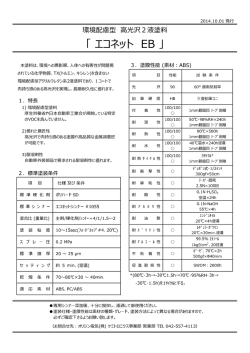
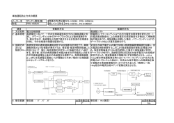
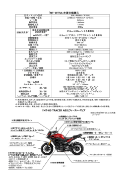
© Copyright 2026 Paperzz