二重ダイアフラム構造のゲージ圧タイプ
アンプ内蔵型圧力トランスジューサ
PRESSURE TRANSDUCERS WITH AMP.
PA-838
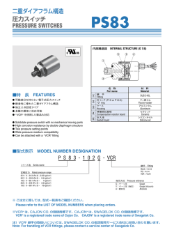
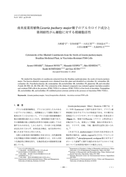
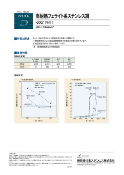
内部構造図 INTERNAL STRUCTURE
PA-838 (G 1/8)
1
5
3
4
2
■特 長 FEATURES
1
O耐食性に優れた二重ダイアフラム構造
O駆動回路、アンプ内蔵タイプ
O温度補償機能内蔵 (0 ∼ 50 °C)
O電流出力タイプ
O継手に ※VCR® を使用した製品も対応
材 料
Material
継 手
SUS 316L
Fitting
O リング (P15)
“O” ring
Fluoro-rubber
3
ケース
アルミニウム
Housing
Aluminum
4
補償抵抗基板
セラミック
5
封入液
2
OHigh corrosion resistance by double diaphragm structure
OBuilt-in amplifier circuit
OIncorporating temperature compensation function (0 ~ 50 °C)
OCurrent output mode
OAvailable with a ※VCR® fitting
名 称
Part name
フッ素ゴム
Compensation resistor board
Ceraminc
シリコンオイル
Sealed liquid
Silicone oil
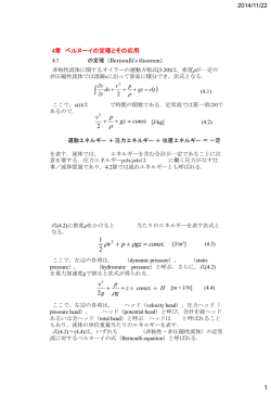
■型式表示 MODEL NUMBER DESIGNATION
PA-838-102G-05
シリーズ名 Series name
温度特性/継手 Thermal error/Fitting
05:± 0.05 % F.S./°C, G 1/8
R2:± 0.05 % F.S./°C, R 1/4
VCR:± 0.05 % F.S./°C, VCR
10:± 0.1 % F.S./°C, G 1/8
定格圧力 Rated pressure range
501:0 ~ 49.0 kPa {0 ~ 0.5 kgf/cm2}
102:0 ~ 98.1 kPa {0 ~ 1 kgf/cm2}
103:0 ~ 981 kPa {0 ~ 10 kgf/cm2}
指示方式 Pressure reference
G:ゲージ圧
Gauge
■型式一覧表 LIST OF MODEL NUMBERS
形(指示方式)
出力方法
Output
Pressure reference
温度ドリフト [% F.S./°C] 定格圧力 kPa {kgf/cm2}
Thermal error
Pated pressure range
継手 Fitting : G 1/8
電流出力
± 0.05
Current output
± 0.10
ゲージ圧 Gauge
0 ~ 49.0
{0 ~ 0.5}
0 ~ 98.1
{0 ~ 1}
PA-838-501G-05
PA-838-102G-05
0 ~ 981
{0 ~ 10}
PA-838-103G-05
継手 Fitting : R 1/4
PA-838-501G-R2
PA-838-102G-R2
PA-838-103G-R2
継手 Fitting : VCR
PA-838-501G-VCR
PA-838-102G-VCR
PA-838-103G-VCR
継手 Fitting : G 1/8
PA-838-501G-10
PA-838-102G-10
PA-838-103G-10
※ ご注文に際しては、上記型式をご確認ください。
※ Verify the above model numbers when placing orders.
※VCR® は、CAJON CO. の登録商標です。CAJON® は、SWAGELOK CO. の登録商標です。
VCR® is a registered trade name of Cajon Co. CAJON® is a registered trade name of Swagelok Co.
注)VCR® 継手の取扱いについては、SWAGELOK CO. の指定販売サービス会社にお問い合わせ願います。
Note: For handling of VCR fittings, please contact a service center of Swagelok Co.
PA-838
PRESSURE TRANSDUCERS WITH AMP.
■標準仕様 STANDARD SPECIFICATIONS
● 特記ない場合、周囲温度 25±5 °C、駆動電圧 24 V DC、負荷抵抗 250 で規定します。
アナログ出力 Analog output
電源
Power
一般仕様 General specifications
Unless otherwise specified, the specs are defined at an ambient temperature of 25±5 °C, excitation voltage of 24 V DC and load resistance of 250 Ω.
PA-838
項 目
型 式
Item
Model number
501G
102G
103G
形(指示方式)
Pressure reference
ゲージ圧 Gauge
定格圧力
Rated pressure range
kPa {kgf/cm }
49.0 {0.5}
98.1 {1}
981 {10}
最大圧力
Maximum pressure
kPa {kgf/cm2}
98.1 {1}
196 {2}
1961 {20}
破壊圧力
Break-down pressure
kPa {kgf/cm2}
147 {1.5}
294 {3}
2942 {30}
動作温度
Operating temp. range
補償温度
Compensated temp. range
動作湿度
Operating humidity
保存温度
Storage temp.
適用媒体
Pressure medium
絶縁抵抗
Insulation resistance
耐電圧
Dielectric strength
封入液
Sealed liquid
シリコンオイル Silicone oil
圧力ポート
Pressure port
G 1/8 (PF 1/8), R1/4 (PT 1/4), 1/4 VCR® ※2
質 量
Net weight
駆動電圧
Supply voltage
V DC
24 ± 10 %
リップル含有率
Ripple content
maximum
10 % (P-P)
出力電流
Output current
mA
4 ~ 20
ゼロ電流
Zero current
mA
4 ± 0.2 (at 25 °C)
スパン電流
Span current
mA
16 ± 0.2 (at 25 °C)
負荷抵抗
Load resistance
2
Thermal error
0 ~ 50 °C(基準温度 25 °C)(Reference temp.: 25 °C)
応答速度
0 ~ 50
°C
35 ~ 85(結露ないこと No condensation)
%RH
°C
− 20 ~ 70(大気圧、湿度 65 %RH 以下 Atmospheric pressure, humidity 65 %RH maximum)
SUS 316L を腐食させない気体及び液体 Corrosive gases/liquids compatible with SUS 316L ※1
100 (500 V DC)
MΩ minimum
500 V AC, 60 s(リーク電流 1 mA 以下 Leakage current 1 mA maximum)
Approx. 140
g
g
0 ~ 500 Ω
直線性/ヒステリシス Linearity/Hysteresis
温度特性
− 20 ~ 70
°C
± 0.5
%F.S.
ZERO %F.S./°C
± 0.05/± 0.1
SPAN %F.S./°C
± 0.05/± 0.1
Response
姿勢の影響(ポート下向き→横向き)
Gravitational effect (From vertical position to horizontal position)
Approx. 2
ms
%F.S.
max.
Approx. 0.5
Approx. 0.3
※1 VCR の場合は、SUS316 を含む In case of VCR type, corrosive gases/liquids compatible with SUS 316L and SUS 316.
※2 O リング付属は G1/8 タイプのみ(正圧:P15)An “O” ring provided for G1/8 type. (Positive pressure : P15)
■環境特性 ENVIRONMENTAL CHARACTERISTICS
試験項目
試験方法(条件 25 ± 5 °C)
Vibration
Test conditions (At 25 ± 5 °C)
10 ~ 500 Hz, 1.5 mm maximum/98.1 m/s2,
3 directions for 2 hours each
衝 撃
490 m/s2, 3 directions for 3 times each
Test item
振 動
Shock
圧力サイクル
Pressure cycling
0 ∼定格圧力 0 ~ Rated pressure, 106 cycles
耐湿性
40 °C, 90 ~ 95 %RH, 240 hrs.
Moisture resistance
変動量
Permissible change
ゼロ電流、スパン電流
それぞれ最大 ± 1 %F.S.
Zero current, Span current:
± 1 %F.S. maximum each
Approx. 0.05
PA-838
PRESSURE TRANSDUCERS WITH AMP.
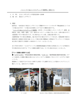
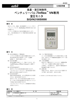
■外形寸法図 OUTLINE DIMENSIONS
OG1/8 タイプ
G1/8 type
(10)
55±1
SNプレートラベル
SN plate label
銘版1(型式ラベル)
Part No. label
22.5
22
12
Unless otherwise specified, tolerance : ± 0.5 (Unit: mm)
PA-838
Wire color
Red
White
Shield
Green
Black
ケーブルブッシュ (ESS-1)
Cable bush (ESS-1)
“O” ring groove depth 1.8
P 15 (正圧)
G 1/8 (PF 1/8)
(SUS 316L)
圧力導入口 M 5 depth 6
Pressure port
圧力導入口
M5 深さ6
Pressure port
M5 depth 6
Connection
Power B
Output
Fitting
N.C.
N.C.
ケース(アルミニウム、アルマイト処理)
Housing (Aluminum with alumite finish)
4 芯ケーブル (φ 3.8)
AWG26 ULNo.2844
4 – core shielded cable
L = 1500 ± 50
SNプレートラベル
SN plate label
銘版1(型式ラベル)
Part No. label
R 1/4 (PT 1/4)
(SUS 316L)
φ 30
(25.4)
8
OR1/4 タイプ
R1/4 type
φ 30
8
8
4 芯ケーブル (φ 3.8)
AWG26 ULNo.2844
4 – core shielded cable
L = 1500 ± 50
ケーブルブッシュ (ESS-1)
Cable bush (ESS-1)
13.5
0
22 –0.3
8
23.5
ケース(アルミニウム、アルマイト処理)
Housing (Aluminum with alumite finish)
56 ± 1
OVCR タイプ
VCR type
SNプレートラベル
SN plate label
4 芯ケーブル (φ 3.8)
AWG26 ULNo.2844
4 – core shielded cable
L = 1500 ± 50
銘版1(型式ラベル)
Part No. label
φ 30
(21.9)
8
1/4 VCR
(SUS 316)
(10)
ケーブルブッシュ (ESS-1)
Cable bush (ESS-1)
(16)
0
19 –0.3
8.5
(26.5)
ケース(アルミニウム、アルマイト処理)
Housing (Aluminum with alumite finish)
59 ± 1
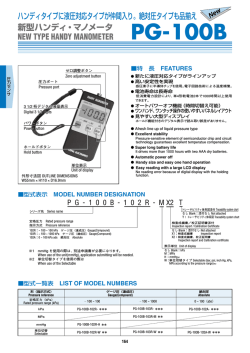
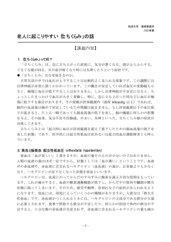
■内部電気回路
■参考外部回路
INTERNAL ELECTRICAL SCHEMATICS
圧力
Pressure
センサ
Sensor
(10)
Power B
主回路
Main circuit
Output
Shield
RECOMMENDED EXTERNAL SCHEMATICS
圧力
Pressure
Power B
センサ
Sensor
主回路
Main circuit
V
RL : 250 Ω Output
Shield
24V DC
© Copyright 2026 Paperzz