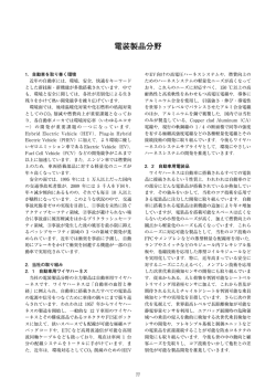
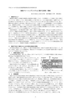
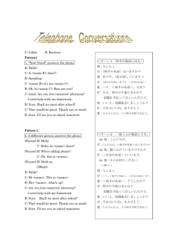
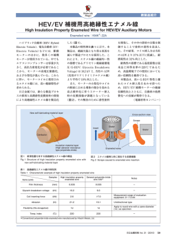
取付けは必ず専門業者に依頼してください。本書はご使用前に必ずお読みください。
商品名
用 途
コード No.
備 考
取説品番
スーパーSQVⅣDキット
自動車部品
71008-AK003
汎用
E04531-K00160-00
2011/3/25 作成
Ver.3-1.01
( 禁無断複写、転載 )
( 株 ) エッチ・ケー・エス
●この度は HKS スーパーSQVⅣDキットをお買い上げいただき誠にありがとうございます。取付けは必ず専門業者に依頼し、
取付け終了後は本書に記載されている内容を守り安全にご使用ください。
● HKS スーパーSQVⅣDは、ターボチャージャー車のスロットルバルブ急閉時にチャンバパイプ内に発生する余剰空気を制
御する部品です。
バルブ作動時にチャンバパイプの空気が抜ける音がしますが異常ではありません。また車種・仕様によって音質・音量が異
なりますのであらかじめ御了承ください。
本書は取付けを行う前に必ずお読みください。
●本書は本製品を安全に取付けていただき、あなたや他の人々への危険や損害を未然に防止するために守っていただきたい注意
事項を記載しています。
●お客様又は第三者が本製品及び付属品を誤使用したことにより受けた損害については、当社では一切その責任を負いかねます
のであらかじめご了承ください。
●本製品を使用して生じた損害や、脱着工賃およびそれに付随する費用、また、自動車を使用することができないことによる損
失等につきましては、一切の補償はいたしかねます。
●本製品はノーマル車輌を基準に製作されております。ノーマル車輌以外に取付けた場合は、本製品の機能・性能及び安全性に
ついて保証いたしかねます。
●本製品は日本国内での使用を目的に設計されたものです。海外では使用しないでください。
This�product�is�designed�for�use�in�Japan�only.It�must�not�be�used�in�any�other�country.
●本製品の仕様は付属品を含め、改良のため予告なく変更をすることがあります。
●本書は予告なく改版することがありますので本製品と本書の整合をご確認ください。
●消耗部品や紛失部品及び本書のご注文はお買上の販売店までお問い合わせください。部品を発注する際は、商品名・コード No.・
車輌型式・エンジン型式を注文先にお伝えください。
本書では下記のような記号を使用し、お客様及び作業者への危険レベルを示しています。
作業者又は使用者が死亡、又は重傷を負う可能性がある場合
作業者又は使用者が障害を負う危険が想定される場合(人損)
拡大物損の発生が想定される場合
(拡大物損とは、当該製造物が原因で誘発された物的損害[例えば、車輌破損及び焼損])
1
●換気の良い場所で取付け作業を行ってください。
・換気の悪い場所で作業すると、爆発及び火災の原因となります。
●本製品及び付属品は運転の妨げになる場所・不安定な場所に取付けないでください。
・運転操作ができなくなり、事故の原因となります。
●本製品は、DC 12 Vマイナスアース車輌専用です。24 V車輌には取付けないでください。
・火災の原因となります。
●バッテリのマイナス端子のターミナルを取外してから作業を行ってください。
・ショート等による火災及び電装部品の破損・焼損の原因となります。
●コネクタを外すときは、断線しないようにコネクタを持って外してください。
・ショート等による火災及び電装部品の破損・焼損の原因となります。
●使用中、本製品に異音・異臭等の異変があった場合には、本製品の使用を直ちに中止し、お買い上げの販売店にお問い合
わせください。
・そのまま使用すると、感電や火災及び電装部品の破損の原因となります。
●運転中、ドライバは、ブーストドライブコントローラーのダイヤル部を操作しないでください。
・事故の原因となります。
●本製品及び付属品の加工・分解・改造等の誤使用及び修理は絶対に行わないでください。
・感電及び車輌の破損・焼損の恐れがあります。
・本来の性能を損なう恐れがあります。
●精密電子機器のため、落としたり強いショックを与えないでください。
・作動不良を起こし、車輌を破損する恐れがあります。
●オイル・水等の異物が混入しないようにしてください。
・作動不良を起こし、車輌を破損する恐れがあります。
●作業を始める前にエンジンルーム内の各部の温度が約 40℃位(手で触れて熱くない程度)に下がっていることを確認し
てください。
・火傷をする恐れがあります。
●高温になる場所・水等がかかりやすい場所を避けて取付けてください。
・作動不良を起こし、車輌を破損する恐れがあります。
●配管及び配線の際に、本製品のホースやハーネス類を取付車輌の燃料パイプ等の配管と一緒に固定しないでください。
・車輌の破損・焼損の恐れがあります。
●配線は断線・ショート・誤配線のないように行ってください。
・感電及び車輌の破損・焼損の恐れがあります。
●スプライスは、必ず付属のものを指定の場所に使用してください。
・接触不良による車輌の破損・焼損の恐れがあります。
●アース線は車輌のボディアースされている金属部分に直接接しているビス等に接続してください。
・接触不良による車輌の破損・焼損の恐れがあります。
●パイプ等に異物が入らないようにウエス等をかけておいてください。
・異物がエンジンに入りエンジンが破損する恐れがあります。
●キットの構成部品をパーツリストに記載してあります。取付け前に異品、欠品の無いことを確認してください。
●ノーマルパーツの取付け取外しはメーカー発行の整備書をよく読んでから行ってください。整備書がお手元にない場合は、
メーカーにてご購入ください。
●本製品の取扱いは慎重に行ってください。落としたり、強いショックを与えないでください。取付け不良や故障の原因になり
ます。
●ボルト、ナット類は適切な工具で確実に締付けてください。必要以上に締付けを行うと、ボルトのねじ部が破損します。
●取付け作業のため、一時的に取外すノーマルパーツは破損又は紛失しないように保管してください。又、ノーマルパーツを
取付ける際は、間違えて取付けないように取外す部品にはマーキングしてください。
2
No. ��������� 名�称 ������������������ 形�状 ���������� 数
No. ��������� 名�称 ������������������ 形�状 ���������� 数
1
ブローオフ本体
1
15
フランジナット
(M6)
1
2
Cリング
1
16
ゴムブッシュ
2
3
Oリング
1
17
ソレノイドバルブ用
ハーネス(橙色・2m)
1
4
ブーストドライブ
コントローラー
1
18
アース線用ハーネス
(黒色・1m)
1
5
ソレノイドバルブ
1
19
保護チューブ
(300mm)
1
6
ホースニップル
(φ4)
2
20
オスギボシ
&スリーブ
1
7
エアフィルタ
1
21
スプライス
2
8
スリーウェイ
(φ6-φ4-φ6)
1
22
収縮チューブ
1
9
スリーウェイ
(φ4-φ4-φ4)
1
23
クワガタ端子
2
10
ブラケット
1
24
エレクトロタップ
3
11
ブラケット用ビス
(M4-8)
2
25
タイラップ
3
12
ボルト
(M6-25)
1
26
両面テープ
1
13
スプリングワッシャ
(M6)
1
27
取扱説明書
1
14
プレーンワッシャ
(M6)
2
28
3
SQV4D_AK003_3-1.01
4
(1) バッテリのマイナス端子(-)からケーブルターミナルを取外してください。
(2) 構成パーツ(ホース、ハーネスの長さ)を考慮して、各部品の取付けレイアウトを決めてください。
ホース、ハーネスが各部品を引っ張らないように余裕を持たせてください。
高温になる場所には取付けないでください。
1.�ブローオフ本体の取付け
(1)�ブローオフパイプのフランジ部にOリングを組付けてくだ
����さい。
(図1)
����このときにOリングが浮かないようにしてください。
����ブローオフ本体の合わせ面及びOリング溝(シール部分)
����にはゴミ・ホコリ等の汚れがないことを確認してくださ
����い。
1
(2)�Cリングプライヤ等を使用してブローオフ本体をブローオ
����フパイプへ組付けてください。
(図1)
Cリングプライヤ等
2
Cリングを組付ける時、必ずテーパ面を上に組付けてくださ
い。(図2)
Cリングを逆に組付けるとブローオフ本体が確実に固定され
なくなります。
3
4
Cリング組付け後、ブローオフ本体が確実に固定されている
か必ず確認してください。
ブローオフ本体が動くようですと確実に固定されていません
のでもう一度やり直してください。但し、ブローオフ本体を
無理に回転させたりこじったりしますと破損する恐れがあり
ますので絶対にしないでください。
ブローオフ本体が確実に固定されていないと走行中にブロー
オフ本体がチャンバ圧で飛ばされて破損する恐れがあります。
1. ブローオフ本体
2. Cリング
3. Oリング
4. フランジ部
図1
テーパ面
ブローオフ本体の向きを変えるときは必ずCリングを緩めて
から行なってください。
Cリングを緩めないでブローオフ本体を回転させたりこじっ
たりしますと破損しますので絶対にしないでください。
図2
ブローオフ本体
フランジ部
Cリング
Cリング溝
Oリング溝
5
Oリング
図3
SQV4D_AK003_3-1.01
2.ソレノイドバルブの取付け
(1)�ソレノイドバルブの端子に取付けてある半透明のキャップ
����を全て取外してください。
(図4)
キャップ
図4
(2)���������端子と ������ �端子にホースニップルを取付けて
����ください。取付ける際は、ネジ部に市販のシールテープ等
����を巻くなどしてエア漏れしないようにしてください。
����(図5)
ホースニップルを取付ける際は、ネジ部に市販
のシールテープ等を巻くなどしてエア漏れしな
いようにしてください。
ホースニップルは手で締め込んだ後、適切な工具
ホースニップルは手で締め込んだ後、適切な工具を用いてさら
に 1 ~ 2 回転締め込んでください。
(座面が設置するまで締め込む必要はありません)
を用いてさらに 1 ~ 2 回転締め込んでください。
(座面が接地するまで締め込む必要はありません)
ソレノイドバルブ
(3)�キットパーツを使用してソレノイドバルブを適当な箇所に
����固定してください。
(図6)
ソレノイドバルブはエキゾーストマニホールド付近など高
温になる場所や水がかからない場所に取付けてください。
バルブが故障する恐れがあります。
�1.
�2.
�3.
�4.
�5.
�6.
�7.
�8.
ソレノイドバルブ
ブラケット
ブラケット用 M4 ビス
ボルト M6-25
スプリングワッシャ M6
プレーンワッシャ M6
フランジナット M6
ゴムブッシュ
図5
ホースニップル
1
2
3
3
4
5
6
8
6
8
固定に使用するボルトは取付け先によっては
長さ・太さ等が合わない場合がありますので、
その際は市販のボルト、ワッシャ等をお買い求めください。
ブラケットは反対の向きでも取付け可能です。
6
車輌への取付け部
7
車輌への取付け部
8
6
図6
3.配管方法
(1) ブローオフバルブ作動用の配管を行ってください。(図7)
ブローオフ本体
ソレノイドバルブ
[COM] 側に接続します
ホースφ4
ホースφ4は本キットには含まれておりません。
図7
(2) ブローオフ本体のニップル部に取付けたφ 4 ホースをタイ
��� ラップで縛り、固定してください。(図7、図8)
タイラップ
φ4ホース
ブローオフ本体
ブローオフ本体を取外す時など、ホースφ 4 をブローオフ本体
から抜く際は、タイラップを外した後、一度ホースφ 4 を切断
し切り込みを入れてから取外してください。
(図8)
ホースφ 4 を引っ張ったり、プライヤー等でこじって抜かない
でください。ブローオフ本体が破損する恐れがあります。
(3)�ソレノイドバルブの [NO] 側ニップルにチャンバ圧がとれる場
����所からホースφ 4 で配管を行ってください。
(図9)
図8
ソレノイドバルブ
[NO] 側に接続します
エアフィルタ
ホースφ4
ホースφ4
チャンバ圧の取出しが
可能な場所に接続して
ください。
ホースφ4は本キットには含まれておりません。
図9
ソレノイドバルブの[NO]側ニップルはチャンバ圧の取出しが可能な場所に接続してください
インテークマニホルド圧ではSQVⅣDが正常に作動しません
7
SQV4D_AK003_3-1.01
1.スプライスの使用方法
(1)�配線を行う電線の被覆を 5mm 程度むいてください。
(2)�電線の被覆をむいた箇所に電線を二重折りし、より合わせ
����てください。
(3)�よった線の上からスプライスでしっかりとかしめてくださ
����い。
(4)�ショートしないように収縮チューブでしっかりと絶縁して
����ください。収縮チューブはキット付属のものを切って使用
����してください。
図 10
2.配線
(1)�ソレノイドバルブのハーネスとソレノイドバルブ用ハーネス(橙色)とアース線用ハーネス(黒色)をそれぞれスプライス
����で接続してください。
(図11)
(2)�アース線用ハーネス(黒色)にクワガタ端子を接続し、ボディアースしてください。
(図11)
アース線を接続する金属部分の塗装やサビをヤスリなどではがしてから接続してください。
図 11
(3) ソレノイドバルブ用ハーネス(橙色)をエンジンルーム側から室内に引き込んでください。
ソレノイドバルブ用ハーネスのエンジンルームと車室の間の隔壁部にかかる部分には付属の保護チューブを使用し、
ハーネスの損傷がないようにしてください。
8
(4)�ソレノイドバルブ用ハーネス(橙色)をオスギボシ・スリーブを使用してブーストドライブコントローラーに接続してくだ
����さい。
(5)�バッテリのマイナス端子を元通りに取付けてください。
(6)�イグニションスイッチオンで約12V出力している線を、テスタまたは検電ドライバなどで探してください。
����この線がIG線(イグニション線)です。線を確認した後にバッテリのマイナス端子を取外してください。
(7)�赤線をIG線にエレクトロタップで接続してください。
(8)�黒線を車輌のアース線にエレクトロタップで接続する、もしくはクワガタ端子を接続してボディアースしてください。
ボディアースする場合はアース線を接続する金属部分の塗装やサビをヤスリなどではがしてから接続してください。
(9) 青線を車輌のアクセル開度信号線にエレクトロタップで接続してください。
電子制御スロットル車に取付ける際は、
青線をアクセルペダルの動き ( 開度 ) を監視している信号線に接続してください。
スロットルセンサ信号線では正常に動作しない恐れがあります。
�� 各配線とも接触不良がないように確実に接続してください。
図 12
9
SQV4D_AK003_3-1.01
ブーストドライブコントローラーは、ソレノイドバルブの動作制御を行う装置です。
1.各部の名称と働き
①トリガースイッチ
④ ON-OFF 切り替えスイッチ
��� 任意のタイミングでSSQVⅣD ( ソレノイドバルブ ) を
��� 作動できます。
��� また、SSQVⅣD ( ソレノイドバルブ ) 作動時に点灯しま
��� す。
��� ※ 5 秒以上長押しますと、安全のため非作動状態に
��� なります。
��� SSQVⅣD ( ソレノイドバルブ ) の作動 (ON)、
��� 非作動 (OFF) を選択します。
②緑インジケータ
⑤赤インジケータ
��� ※スイッチを OFF にしても空吹かし時にSQV
��� 本体が作動することがあります。
���
③SSQVⅣD作動ポイント設定ボリューム
⑥SSQVⅣD作動時間設定ボリューム
��� SSQVⅣD ( ソレノイドバルブ ) を作動させるアクセル
��� ポイントを設定します。
��� SSQVⅣD ( ソレノイドバルブ ) の作動時間を設定
��� します。
2.インジケータ点灯状況一覧
10
3.動作設定
ボリュームの操作はゆっくり行ってください。急に回したり大きな力をかけると破損するおそれがあります。
(1)�10 ページ③で示した SSQV Ⅳ D 作動ポイント設定ボリューム ( 以下③ボリュームと省略 ) を設定します。
����1.
� エンジンをかけます。アイドリング状態でアクセルペダルは踏まないでください。
����2.
� ③ボリュームを左一杯から、ゆっくり右に回していき、①トリガースイッチが点灯する位置で止めます。
��������� トリガースイッチは数秒後に消灯し、緑インジケータが点灯します。数秒経っても緑インジケータが点灯しない場合には
��������� もう少し右に回します。
����これで作動ポイント設定ボリュームの設定は完了です。
①トリガースイッチ
②緑インジケータ
③ボリューム
ゆっくり右に回す
点灯したら止める
図 13
(2)�10 ページ⑥で示した SSQV Ⅳ D 作動時間設定ボリューム ( 以下⑥ボリュームと省略 ) を設定します。
����1.
� ⑥ボリュームを右一杯にします。SSQV Ⅳ D( ソレノイドバルブ ) の作動時間が長い場合には、左に回して作動時間を短く
��������� 調整していきます。
��������� 設定出来る時間は約0秒~約8秒となります。なお、左一杯の位置は、作動時間が約0秒となります。
����これで作動時間設定ボリュームの設定は完了です。
⑥ボリューム
右いっぱいに回しておいてから、左に回して調整する
11
図 14
SQV4D_AK003_3-1.01
1.ブーストドライブコントローラーの取付け
(1) 取付け位置の汚れ(ほこりや油分等)を中性洗剤等で取除いてください。
(2) 両面テープを使用してブーストドライブコントローラーを固定してください。
2.ホース・ハーネスの固定
(1) ホース・ハーネスを付属のタイラップを使用して固定してください。
エンジンの振動や揺れを吸収できるように余裕を持たせてください。
ホースを固定する際は、ホースがつぶれないようにしてください。
(1) 取外した純正部品を元通りに取付けてください。
(2) バッテリのマイナス端子(-)にケーブルターミナルを取付けてください。
� エンジン始動前の確認
��������������������������� 確
認
項
目 �������������������������� 確
認
� パイプ・ホースの配管が間違っていないか。
� ホースに緩みはないか。
� ホースが切れたり、裂けたりしていないか。
� ホースバンドが確実に締まっているか。
� ボルト・ナット類の締め忘れはないか。
� ホース・ハーネス及び取付けた部品が、他の部品等と干渉していないか。
� ホース・ハーネスは確実に固定されているか。
� 配線の接続箇所は間違っていないか。
� コネクタ・スプライスは確実に接続されているか。
� スプライスは指定のものを使用し、確実にかしめてあるか。
� 本製品及び付属品が運転の妨げにならないように確実に固定されているか。
� バッテリのマイナス端子のターミナルが元通りに取付けてあるか。
� エンジン始動後の確認
��������������������������� 確
認
項
目 �������������������������� 確
� 各部からエア漏れがないか。
� 軽く 2,3 度空吹かしを行いブローオフアッセンブリが作動しているか。
� 部品による干渉音はないか。
� アイドリング状態に異常はないか。
� ホース・ハーネスが引張られていないか。
� エンジンを停止した後、各部が緩んでいないか。�( 再度取付部の締付け確認 )
12
認
リターン用ニップル取付け方法
スーパーSQVⅣDから吐出される空気をサクションリターンする際は別売のリターンニップルをご利用ください。
ニップルより先のリターン用パーツ(パイプ・ホース・ホースバンド類)は本キット・リターンニップルともに付属しており
ませんので、別途お買い求めください。
スーパー SQV リターンニップル ( 別売 ) �� ニップル外径φ 19������ コード No.�:�71002-AK003
���������������������������������������� ニップル外径φ 29������ コード No.�:�71002-AK004
1. 右図の矢印で示す 4 本のボルトを外し、ファンネルを取外し
�� てください。
他の 4 本は本体固定用ですので、絶対に外さな
いでください。
2. ファンネルを取外すとフィンを取外すことができます。
3. 逆の手順でリターン用ニップルを取付け、ファンネルをボル
�� ト ( 再使用 ) で再度固定してください。
快適に運転していただくために、お車を運転する前には必ず日常点検を行ってください。
●安全な整備はドライバーの責任です。必ず実施してください。
●ユーザーマニュアルに記載されている事項以外は専門業者に依頼してください。
●スーパーSQVⅣDの性能を維持するため、エアフィルタの交換は定期的に行ってください。
( 交換の目安 )3,000 ~ 5,000km または 3 ヶ月~ 6 ヶ月
但し、使用方法及び環境により条件が異なりますので汚れ具合によっては早めの交換をおすすめします。
交換エアフィルタは別売りです。 � �品名 スーパーSQV交換フィルター
●故障等の修理はお客様ご自身では絶対に対処せず、必ず専門業者に依頼してください。
●走行中、異音・異臭・振動等の異変があった場合には、ユーザーマニュアルに従って対処してください。
●本製品を譲られる時は、必ず次のオーナーのために取扱説明書をお渡しください。
●本製品をお車から取外す際には、必ず専門業者に依頼してください。
本製品に関するお問い合わせは、専門業者またはお買上の販売店までお問い合わせください。
本書の記載内容は、予告無しに変更することがありますのであらかじめご了承ください。
13
SQV4D_AK003_3-1.01
SuperSQV IV D Kit
INSTALLATION MANUAL
NAME OF PRODUCT
PART NUMBER
REMARKS
Super SQV Ⅳ KIT
71008-AK001
Universal Application
Published in March, 2011 by HKS Co., Ltd. (Unauthorized reproduction is strictly prohibited.)
This manual assumes that you have and know how to use the tools and equipment necessary to safely perform
service operations on your vehicle. This manual assumes that you are familiar with typical automotive systems
and basic service and repair procedures. Do not attempt to carry out the operations shown in this manual unless
these assumptions are correct. Always have access to a factory repair manual. To avoid injury, follow the safety
precautions contained in the factory repair manual.
The HKS SuperSQV IV D Kit is designed to control the excessive air generated inside the chamber pipe once the
throttle is released. The SuperSQV IV D makes a unique sound when the air is blown-off from the chamber pipe.
The sound will vary depending on the vehicle’s specifications. To install this kit, a SSQV flange and 4mm hose are
required (not included in this kit).
●This manual indicates items you need to pay attention to in order to install this product safely and lists precautions
to avoid any possible damage and/or accidents.
●HKS will not be responsible for any damage caused by incorrect installation and/or use of this product.
●HKS will not be responsible for any labor expenses, related fees or losses incurred during vehicle downtime.
●This product was designed based on installing it onto a factory vehicle. The performance and/or safety cannot be
guaranteed if this product was installed onto other inapplicable vehicles.
●The specifications of this product are subject to be changed without notice.
●This manual is subject to be revised without notice.
●For any lost parts, consumables or manual, please contact an Authorized HKS Dealer.
14
SAFETY PRECAUTIONS
WARNING
● Make sure to work on the vehicle in a well-ventilated area to prevent possible explosion or fire.
● To avoid possible accidents, do not mount the unit in areas where the driver may become distracted during
driving or the product cannot be mounted securely.
● Do not install this product on a 24V vehicle. It may cause a fire.
● Make sure to disconnect the negative cable from the battery to avoid possible damage to other electronic
parts and/or a fire caused by a short circuit.
● Make sure to hold and remove wire connectors properly to avoid possible damage to other electronic parts
and/or a fire caused by disconnection or a short circuit.
● Stop using this product if any unusual problems should occur. Consult your Authorized HKS Dealer
immediately.
● Do not operate this product while driving to avoid possible accidents.
CAUTION
● Do not modify, disassemble, misuse or repair this product and supplied parts to avoid any damage to the
product, engine and loss of its original function.
● Handle parts with extra care at all times to protect the parts and vehicle from possible damage.
● Avoid allowing oil and/or water from entering the unit. It may damage the unit.
● Prior to installation, make sure the engine bay temperature has cooled to approximately 40℃ /104°F.
Failure to let the engine cool down properly can lead to severe burns.
● To avoid possible malfunction and damage to the engine, install the unit away from areas with excessive heat
and water/moisture.
● Do not tie or bundle any hoses, wires or harnesses to any vehicle fuel lines. It may cause a fire and/or severe
damage to the vehicle.
● Make sure all connections and wiring are correct and do not become shorted or disconnected. If so, it may
cause an electrical shock or damage the vehicle.
● Use the provided splice connectors and install them to the correct positions. If not, it may cause serious
damage to the vehicle.
● Connect the ground wire to a good chassis ground. If not, it may cause damage to the vehicle.
● Insert clean rags into open piping to prevent contaminants from entering the pipes.
- If neglected, contaminants in the piping can lead to engine damage.
- Make sure that all of the parts listed in the Parts List are included in the kit.
- Reference the factory service manual for the vehicle when removing factory parts.
- Be careful when handling this product; avoid dropping or subjecting it to excessive impact. Failure to do so may
result in product damage or improper installation.
- Use the proper tools when tightening nuts and bolts. If over tightened, the bolts may become damaged.
- Keep the removed factory parts in a safe place for ease of re-installation at a later date (if necessary).
When reinstalling the removed factory parts, make sure to reinstall them correctly.
15
SQV4D_AK003_3-1.01
No.
Description
Image
QT No.
1
SSQVIV D Assy
1
15
Flange Nut
(M6)
1
2
C-Clip
1
16
Rubber Bushing
2
3
O-Ring
1
17
Solenoid Valve Wire
(Orange / 2m)
1
4
Boost Drive
Controller
1
18
Ground Wire
(Black / 1m)
1
5
Solenoid Valve
1
19
Protection Tube
(300mm)
1
6
4mm Hose Fitting
2
20
Male Bullet Connector &
Sleeve
1
7
Air Filter
1
21
Splice Terminal
2
8
T-Fitting
(6mm-4mm-6mm)
1
22
Heat Shrink Tube
1
9
T-Fitting
(4mm-4mm-4mm)
1
23
Spade Terminal
2
10
Bracket
1
24
Electro Tap
3
11
Bracket Screw
(M4-8)
2
25
Tie Wrap
3
12
Bolt
(M6-25)
1
26
Double-sided Tape
1
13
Lock Washer
(M6)
1
27
Instruction Manual
1
14
Flat Washer
(M6)
2
28
16
Description
Image
QT
17
SQV4D_AK003_3-1.01
(1) Disconnect the negative cable from the battery.
(2) Check the length of the provided wires and determine the installation layout.
NOTE:
Make sure to leave extra slack when routing the hoses and wires.
Install the unit away from areas with excessive heat.
1. INSTALLATION OF SSQV IV D ASSEMBLY
(1) Install the O-ring in the groove of the blow-off pipe flange.
(Dia.1) Make sure the O-ring is seated properly. Also, make
sure the groove and bottom side of the SSQV IV D are clean.
(2) Connect the SSQV IV D to the flange using the provided
C-clip with Snap Ring pliers. (Dia.1)
NOTE:
The tapered side of the C-clip should be facing up. (Dia.2) If the
flat side is facing up, the SSQV IV D will not seal correctly.
After installing the C-clip, make sure the SSQV IV D is securely
mounted. If the SSQV IV D mounting is loose, remove the parts
and reinstall them. When removing the SSQV IV D, do not force
or rotate the unit to avoid any possible damage.
If the SSQV IV D is not securely mounted, it can come apart while
driving due to the air chamber pressure.
If the SSQV IV D needs to be rotated, always loosen the C-clip
first. If neglected, the SSQV IV D base may get damaged.
18
2. INSTALLATION OF SOLENOID VALVE
(1) Remove all 3 caps from the Solenoid Valve as shown in
Diagram 4.
(2) Install the hose fittings to the
terminal and
terminal. Wrap the threaded section with Teflon
tape to prevent air leakage. (Dia.5)
NOTE:
After tightening the hose fittings by hand, tighten them another
one to two turns using the appropriate tools. (It is not necessary
to tighten the fittings to the point where the nut touches the pipe.)
(3) Assemble and securely mount the Solenoid Valve using
the kit parts. (Dia.6)
CAUTION
Do not install the Solenoid Valve in areas with excessive heat or that are exposed to water such as around
the exhaust manifold.
19
SQV4D_AK003_3-1.01
3. CONNECTION OF SSQV IV D & SOLENOID VALVE
(1) Connect a 4mm hose to the SSQV IV D and the Solenoid Valve as shown in Diagram 7.
(2) Secure the 4mm hose connected to the SSQV IV D Fitting
using a Tie Wrap. (Dia.7, 8)
NOTE:
When uninstalling the SSQV IV D Assy or when removing the
4mm hose from the SSQV IV D Assy, remove the Tie Wrap, cut
the hose past the port on the SSQV IV D Assy, and slice the
4mm Hose length-wise and then remove the 4mm hose. (Dia.8)
Do not pull or wriggle the 4mm Hose using pliers or other tools
to prevent damage to the SSQV IV D Assy.
(3) Connect a 4mm hose to the Solenoid Valve’s
and to the air chamber as shown in Diagram 9.
side
20
1. SPLICING
(1) Strip 5mm of insulation off each wire as shown in
Diagram 10.
(2) Twist the wires together.
(3) Crimp the twisted wires using a splice terminal.
(4) Insulate the splice terminal and wires by heating the Heat
Shrink Tube.
NOTE:
Cut the tube to the appropriate length and slide it over the
open end of the wire to get it in the correct position.
2. WIRING
(1) Connect the Solenoid Valve wires to the orange and black wires using the splice terminals (or solder) and the Heat Shrink
Tube as shown in Diagram 11.
(2) Connect the Spade Terminal to the black ground wire and connect to a good chassis ground. (Dia.11)
NOTE:
Remove any paint or rust from the grounding point.
(3) Pull the orange Solenoid Valve wire from the engine compartment into the vehicles interior.
NOTE:
Protect the portion of the Solenoid Valve wire that comes in contact with the vehicles firewall (between the engine compartment and the interior) using the Protection Tube as shown in Diagram 11.
(4) Connect the orange Solenoid Valve wire to the Boost Drive Controller using the Male Bullet Connector and Sleeve.
21
SQV4D_AK003_3-1.01
(5) Reconnect the negative cable to the battery.
(6) Turn the ignition on to find the 12V IG wire using a voltage meter or test light.
Disconnect the negative cable from the battery.
(7) Connect the red wire to a 12V IG source using the Electro Tap.
(8) Connect the black wire to a vehicle ground wire or connect the Spade Terminal to a good chassis ground.
NOTE:
Remove any paint or rust from the grounding point.
(9) Connect the blue wire to the accelerator pedal position signal wire using the Electro Tap.
NOTE:
When installing the controller on a vehicle with an electronic throttle control, connect the blue wire to the signal wire that monitors
the accelerator pedal position. The controller may not function properly if the blue wire is connected to the throttle sensor signal.
Make sure to connect all wires correctly to prevent possible malfunctions.
22
1. NAMES AND FUNCTIONS
① Trigger Switch
④ ON-OFF Switch
Press this switch to activate the SSQV IV D.
This switch is also activated when the SSQV IV D is
triggered by the accelerator pedal.
※ If the Trigger Switch is pressed longer than 5 sec.,
the SSQV IV D will deactivate for safety.
This switch is to turn on and off the SSQV IV D.
※ The SSQV unit may be activated when revving
the engine while in neutral even after the switch is
off.
② Green Indicator
⑤ Red Indicator
③ Throttle Volume
⑥ SSQV IV D Timer Volume
Turn the volume to set the acceleration start point of
the SSQV IV D.
Turn the volume to set the operating time of the
SSQV IV D.
2. INDICATOR CONDITIONS
23
SQV4D_AK003_3-1.01
3. OPERATION SETTING
NOTE:
Turn the volume slowly to prevent any damage to the product.
(1) Set the acceleration position to activate the SSQV IV D by turning the Throttle Volume ( ③ on page 23).
1. Start the engine and let it idle.
2. Turn the ③ volume to the far left; then, turn the volume to the right slowly until the ① Trigger Switch turns on.
A few seconds later, the ① Trigger Switch will turn off, and the ② Green Indicator will turn on. If the ② Green Indicator is
not on, turn the volume to the right a little more.
The Throttle Volume setting is now complete.
(2) Set the operating time of the SSQV IV D by turning the Timer Volume ( ⑥ on page 23).
1. Turn the ⑥ volume to the far right. If the operating time of the SSQV IV D (Solenoid Valve) is activated too long, turn
the ⑥ volume to the left to shorten the time.
The setting range is between approximately 0 to 8 seconds; the far left volume is 0 seconds.
The Timer Volume setting is now complete.
24
1. MOUNTING BOOST DRIVE CONTROLLER
(1) Remove any dirt, dust and/or oil from the mounting surface of the Boost Drive Controller.
(2) Mount the BDC using the double-sided tape.
2. SECURING HOSES AND WIRES
(1) Secure all hoses and wires using the provided Tie Wraps.
NOTE:
Leave some slack when routing the wires and hoses to avoid tension during engine movement.
When tying the hoses, make sure not to pinch the hoses.
(1) Reinstall all removed factory parts.
(2) Reconnect the negative cable to the battery.
Check the following after the installation process is complete.
(1) Check the following before starting the engine:
● Make sure all pipes and hoses are routed and connected correctly.
● Make sure there are no loose hoses.
● Make sure hoses are not damaged in any way.
● Make sure all hose clamps are tightened.
● Make sure all bolts and nuts are tightened.
● Make sure all installed components do not come in contact with other parts.
● Make sure hoses and wires are properly secured.
● Make sure wiring is done correctly.
● Make sure splice connectors are connected securely.
● Make sure proper splice connectors are used and crimped securely.
● Make sure the installed parts are mounted securely and do not interfere with driving.
● Make sure the negative cable terminal is securely attached to the battery.
(2) Start the engine and check the following:
● Make sure air is not leaking.
● Make sure the RPM rises smoothly after revving the engine 2-3 times while in neutral.
● Make sure the installed parts are not hitting each other.
● Make sure there are no idling issues.
● Make sure there is no excessive tension on hoses and/or wires.
● Make sure there are no loose bolts after turning off the engine. Re-tighten if necessary.
25
SQV4D_AK003_3-1.01
If it is necessary to recirculate the SSQV IV D back into the suction pipe, please refer to the instructions below. Miscellaneous
hose clamps, suction pipe fitting and return hose are not included in this kit.
SSQV Recirculation Fitting (sold separately)
For 1” ID Hose
For 19mm ID Hose
For 29mm ID Hose
P/N : 71002-XA001
P/N : 71002-AK003
P/N : 71002-AK004
1. Remove 4 bolts (per diagram) and remove the cover.
NOTE
Do not remove the remaining 4 bolts as they are to stay
affixed to the SSQV IV D main body.
2. After removal of the cover, the fin insert can be
removed and replaced with the recirculation fitting.
3. Install the recirculation fitting. Reinstall the cover and
retighten the 4 bolts.
Proper maintenance of this product is necessary in order to maintain the safety, reliability, and function of this product.
- Maintenance is the responsibility of the driver/owner.
- If work needs to be performed outside the scope of this manual, consult a professional.
- For optimal performance, it is recommended to replace the air filter every 3,000-5,000km or every 3-6 months.
Replacement air filters are sold separately.
- If the vehicle gets damaged, have the repairs performed by a professional.
- If you experience any abnormal noises, scents, or vibrations from the vehicle while driving, reference the vehicle’s
Service Manual.
- If this product is ever re-sold, please give this Instruction Manual to the new owner.
- When removing this product from the vehicle, please consult a professional.
26
27
SQV4D_AK003_3-1.01
28
© Copyright 2026 Paperzz