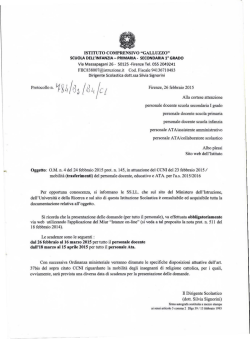
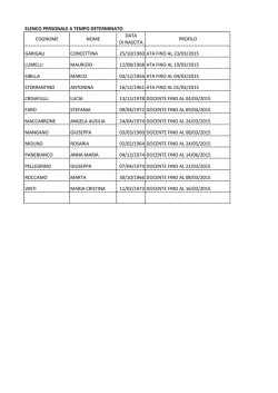
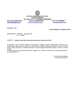
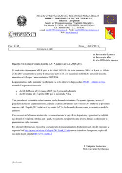
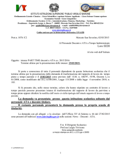
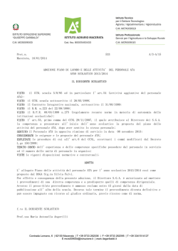
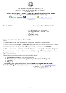
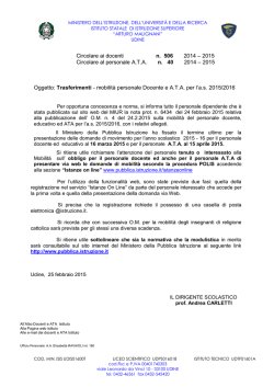
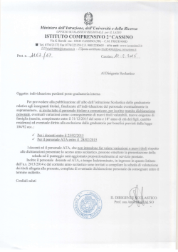
STR50-21-BU29504-0017
BU29504KV
Serial ATA Bridge Chip
Description of Functions
Ver. 0.97
1 / 43
2007/Sep
STR50-21-BU29504-0017
Table of Contents
Page No.
1 General
・・・・・・・・・・・・・・・・・・・・・ 5
2 Features
・・・・・・・・・・・・・・・・・・・・・ 6
2.1
List of Functions
・・・・・・・・・・・・・・・・・・・・・ 6
2.3
Functional Precautions
・・・・・・・・・・・・・・・・・・・・・ 7
3 Block Diagram
・・・・・・・・・・・・・・・・・・・・・ 8
3.1
PHY Block
・・・・・・・・・・・・・・・・・・・・・ 8
3.2
LINK Block
・・・・・・・・・・・・・・・・・・・・・ 8
3.3
Transport Block
・・・・・・・・・・・・・・・・・・・・・ 9
3.4
Application Block
・・・・・・・・・・・・・・・・・・・・・ 9
3.5
SCR Block
・・・・・・・・・・・・・・・・・・・・・ 9
3.6
REG Block
・・・・・・・・・・・・・・・・・・・・・ 9
4 Outside Dimensions
・・・・・・・・・・・・・・・・・・・・・10
5 Description of Pins
・・・・・・・・・・・・・・・・・・・・・11
5.1
Pin Assign
5.2
Table of Pin Assign (Normal / Reverse) ・・・・・・・・・・・・・・・・・・・・・12
5.3
Description of Pin Functions
6 ATA / ATAPI Commands
・・・・・・・・・・・・・・・・・・・・・11
・・・・・・・・・・・・・・・・・・・・・13
・・・・・・・・・・・・・・・・・・・・・18
6.1
List of Commands
・・・・・・・・・・・・・・・・・・・・・18
6.2
Vendor Commands
・・・・・・・・・・・・・・・・・・・・・26
6.2.1 SCR Access
・・・・・・・・・・・・・・・・・・・・・27
6.2.2 Register Map
・・・・・・・・・・・・・・・・・・・・・28
7 Electrical Specifications
・・・・・・・・・・・・・・・・・・・・・34
7.1
Absolute Maximum Rating
・・・・・・・・・・・・・・・・・・・・・34
7.2
Operating Conditions
・・・・・・・・・・・・・・・・・・・・・35
7.3
Electrical Characteristics
・・・・・・・・・・・・・・・・・・・・・36
8 Evaluation Results
・・・・・・・・・・・・・・・・・・40
8.1
Results from Connectivity Verification
・・・・・・・・・・・・・・・・・・40
8.2
SATA Compliance Test Results
・・・・・・・・・・・・・・・・・・42
2 / 43
2007/Sep
STR50-21-BU29504-0017
Figure 1-1 Connection Mode Chart
・・・・・・・・・・・・・・・・・ 5
Table 2-1
・・・・・・・・・・・・・・・・・ 6
List of Functions
Figure 3-1 BU29504 Block Diagram
・・・・・・・・・・・・・・・・・ 8
Figure 4-1 VQFP64 Pin : Outside Dimensions ・・・・・・・・・・・・・・・・・10
Figure 5-1 Pin Positions
・・・・・・・・・・・・・・・・・11
Table 5-1 Table of Pin Positions
・・・・・・・・・・・・・・・・・12
Table 5-2 Definition of Pin Types
・・・・・・・・・・・・・・・・・13
Table 5-3 Serial ATA Interface
・・・・・・・・・・・・・・・・・13
Table 5-4 Parallel ATA Interface
・・・・・・・・・・・・・・・・・14
Table 5-5 Operation Control Interface
・・・・・・・・・・・・・・・・・16
Table 5-6 Power Supply / Ground
・・・・・・・・・・・・・・・・・17
Table 6-1 PIO Data-In Commands
・・・・・・・・・・・・・・・・・18
Table 6-2 PIO Data-Out Commands
・・・・・・・・・・・・・・・・・19
Table 6-3 DMA Data-In Commands
・・・・・・・・・・・・・・・・・20
Table 6-4 DMA Data-Out Commands
・・・・・・・・・・・・・・・・・20
Table 6-5 Commands for Host Mode Only
・・・・・・・・・・・・・・・・・20
Table 6-6 PACKET / DIAG Commands
・・・・・・・・・・・・・・・・・20
Table 6-7 Non-Data Commands
・・・・・・・・・・・・・・・・・21
Table 6-8 PACKET Commands
・・・・・・・・・・・・・・・・・23
Table 6-9 ROHM Special Function Register Configuration ・・・・・・・・・・・・26
Table 6-10 Register Map Address for Special Functions
・・・・・・・・・・・・28
Table 6-11 Description of Register Map
・・・・・・・・・・・・・・・・・29
Table 7-1 Absolute Maximum Rating
・・・・・・・・・・・・・・・・・34
Table 7-2 Operating Conditions
・・・・・・・・・・・・・・・・・35
Table 7-3 Circuit Current
・・・・・・・・・・・・・・・・・36
Table 7-4 Characteristics of Digital Circuit Input / Output Voltage ・・・・・・・・・ 37
Table 7-5 AC Characteristics of OSC Circuit
・・・・・・・・・・・・・・・・・37
Table 7-6 Circuit Forms
・・・・・・・・・・・・・・・・・38
3 / 43
2007/Sep
STR50-21-BU29504-0017
Instructions for Use
Although we believe that the examples of application circuit shown in this instruction should be
recommended, please further make sure of characteristics of the product in prior to use.
When using the product with changed external circuit constant, please allow for sufficient margin,
considering its static/transient characteristics, external parts and variability of our IC’s.
Please understand that we have not confirmed the patent right enough.
This product is designated for use in general electronic devices.
Therefore, please contact our sales liaison in advance of using it in such devices or equipments as
to require extremely high reliability and also to threaten human life directly by their failure or
malfunction.
Although we believe that the application circuits, etc. shown in this specification are accurate and
reliable as for eliciting the characteristics of the product, we are not responsible for any problem
concerning circuits or industrial right caused by using the product.
This product is not designated for radiation resistance.
4 / 43
2007/Sep
STR50-21-BU29504-0017
11 G
Geenneerraall
BU29504 (hereinafter called ‘this LSI’) is the Serial ATA to Parallel ATA Bridge LSI, in which the Physical
layer, Link layer, Transport layer, Application layer of Serial ATA, and the Parallel ATA interface are all
integrated in one chip. By adapting a complete hard wired structure without a operational processor
mounted, we have actualized high processing capacity and low power consumption.
As the Serial ATA interface used in this LSI complies with the Serial ATA Standard, and the Application
layer corresponds to the ATA/PACKET commands, it is possible to establish a storage system consisting of
HDD, CD or DVD, etc.
Since this LSI has a bridge function for both modes of the Host/Device (ref. Figure 1-1), it is possible to
connect the old Parallel ATA device to the latest Serial ATA Host Bus adaptor, or connect the latest Serial
ATA device to the old Parallel ATA Host Bus adapter.
Host side
Device side
(PC / Controller)
(HDD / CD / DVD, etc.)
Bridge LSI
Parallel ATA
Serial ATA
Host mode
Host side
Device side
(PC / Controller)
(HDD / CD / DVD, etc.)
Bridge LSI
Parallel ATA
Serial ATA
Device Mode
Figure 1-1
Connection Mode Chart
5 / 43
2007/Sep
STR50-21-BU29504-0017
22 FFeeaattuurreess
22..11 LLiisstt ooff FFuunnccttiioonnss
Table 2-1
List of Functions
BU29504KV
Serial ATA Revision
Revision 1.0a
(Usage Model)
(Gen1:1.5Gbps)
ATA/ATAPI PIO MODE
0/1/2/3/4
ATA/ATAPI MDMA MODE
0/1/2
ATA/ATAPI UDMA MODE
0/1/2/3/4/5/6
CMOS process
0.18μm
Input Voltage
1.8/3.3V
Outside XTAL
25MHz
Package
VQFP64
HBM/MM
±4000V/±400V
Port Multiplier
○
SSC(spread spectrum clock)
○(※1)
PACKET Command feature set
○
48-bit Address feature set
○
Serial ATA power saving modes
○
Serial ATA BIST operation
○
Serial ATA hot-plug
○
(※1)Refer to the description related to SSC in clause 2.2.
6 / 43
2007/Sep
STR50-21-BU29504-0017
22..22 FFuunnccttiioonnaall P
Prreeccaauuttiioonnss
There will be a connection problem with Marvell 88i8030-B2P when SSC is
switched ON (no problem will occur with any models after B4P).
When resetting from the Partial/Slumber modes, Scramble will be stopped until
receiving a command.
Different sequence of power-on procedures for each supply voltage (VCCO,
VCCK, AVDDH, and AVDDL) will not cause any breakdown or malfunction of
LSI. This applies also to the power-off procedures.
When using the product in the Host mode and also in Slave type, as DASP will
be released when receiving the first FIS, there would be a connection problem
with the Master which samples DASP after the first FIS is received (ref. Figure
2-1).
When operating the product in the Device mode, receiving the DMAT Primitive
(DMA Terminate) from the Host is not supported. Do not output a DMAT
Primitive signal from the Host side to be connected when operating in the
Device mode.
In the Transfer mode higher than UDMA4, the actual throughput will not reach
the standard of transfer rate (approximately 45MB/s in the Transfer mode of
UDMA4).
Receiving a command = A0h (PACKET Command) with HDD connected to the
product in the Device mode will cause a freeze. It can be reset by Software
Reset.
When SSC is turned on, it is confirmed that there is a connectivity problem
between devices made of old Marvell( 88i8030-B2P).
When SSC is turned on, a primitive error might occur according to the device
because a permissible margin in connected, compatibility is not enough.
RESETn
DASPn
PDIAGn
Figure 2-1
7 / 43
2007/Sep
STR50-21-BU29504-0017
33 B
Blloocckk D
Diiaaggrraam
m
Application
Transport
LINK
PHY
Block
Block
Block
Block
Serial
Parallel
ATA
ATA
REG Block
Figure 3-1
SCR Block
UART
BU29504 Block Diagram
3.1 PHY Block
PHY block initializes the Serial ATA Bus with an Out Of Band (OOB) signal such as
COMRESET or COMINIT/COMWAKE, etc.
When a data transfer request is received from the LINK block, arbitration is executed, the
data is serialized and transferred via cable.
If data is received via cable, it is parallelized and transferred to the LINK block.
3.2 LINK Block
If the LINK block receives a data transfer request from the Transport block, it encodes the
data, appends CRC data, randomizes it and issues a transfer request to PHY.
When data is received from the PHY block, randomized data is released, decoded and
transferred to the Transport block if there is no error in CRC.
8 / 43
2007/Sep
STR50-21-BU29504-0017
3.3 Transport Block
If the Transport block receives a data transferring request from the Application block, it
packetizes the data and issues a data transferring request to the LINK block.
As for Serial ATA, this packet is called ‘Frame Information Structure (FIS).’
When receiving data (FIS) from the LINK block, it is transferred to the Application block if
there is no error in the data.
3.4 Application Block
When the Application block receives data or command transferring request from the
Parallel ATA interface, it issues a data transferring request to the Transport block.
When receiving data from the Transport block, it determines a data command and
transfers the data to the Parallel ATA interface in an appropriate format for the content of
the data.
3.5 SCR Block
SCR (Status and Control Registers) block is defined in the Serial ATA specification in order
to obtain detailed data about the Serial ATA.
This LSI supports vendor commands to access to the group of registers from the Parallel
ATA Bus and UART when operating in the Host mode (20 pin: MODE2 = 1).
3.6 REG Block
This LSI supports not only SCR but also the collection of registers to obtain or control the
data inside the LSI.
REG block is writable and readable by vendor commands, just like SCR.
9 / 43
2007/Sep
STR50-21-BU29504-0017
44 O
Ouuttssiiddee D
Diim
meennssiioonnss
Figure 4-1
TQFP64 Pin: Outside Dimensions
BU29504KV
LOT No.
10 / 43
2007/Sep
STR50-21-BU29504-0017
55 D
Deessccrriippttiioonn ooff P
Piinn
CSn[0]
CSn[1]
PDIAGn
UAO
VCCO
UAI
DGND
VCCK
PHYRDY
PMEN
FXDMA
CLKSEL[1]
CLKSEL[0
SSCEN
DASPn
MSSEL
48
47
46
45
44
43
42
41
40
39
38
37
36
35
34
33
5.1 Pin Assign
49
32
TXP
DA[0]
50
31
TXN
DA[1]
51
30
AGND
SP
52
29
AVDDL
INTRQ
53
28
RXN
DMACKn
54
27
RXP
IORDY
55
26
REXT
VCCK
56
25
AGND
DGND
57
24
AVDDH
DIORn
58
23
XTALO
DIOWn
59
22
XTALI
DMARQ
60
21
ATAIOEN
DD[15]
61
20
MODE[2]
DD[0]
62
19
MODE[1]
DD[14]
63
18
MODE[0]
DD[1]
64
17
PORn
BU29504KV
6
7
8
9
10
11
12
13
14
15
16
DD[4]
DGND
VCCK
DD[10]
DD[5]
DD[9]
DD[6]
DD[8]
DD[7]
RESETn
4
VCCO
DD[11]
3
DD[12]
5
2
DD[2]
DD[3]
1
LOT No.
DD[13]
DA[2]
Figure 5-1
Pin Positions
11 / 43
2007/Sep
STR50-21-BU29504-0017
5.2 Table of Pin Assign (Normal / Reverse)
It is possible to switch the input/output pins for BU29504 (ref. Table 5-1), which is valid only
for the Device mode setting and controlled by PDIAGn pin.
PDIAGn = 0 : Normal Order
PDIAGn = 1 : Reverse Order
Table 5-1
Table of Pin Positions
Pin
Normal Order
Reverse Order
Pin
Normal Order
Reverse Order
1
DD[13]
DD[0]
48
CSn[0]
DD[7]
2
DD[2]
DD[15]
49
DA[2]
DD[8]
3
DD[12]
DMARQ
50
DA[0]
DD[6]
5
DD[3]
DIOWn
51
DA[1]
DD[9]
6
DD[11]
DIORn
52
SP
DD[5]
7
DD[4]
DMACKn
53
INTRQ
DD[10]
10
DD[10]
INTRQ
54
DMACKn
DD[4]
11
DD[5]
SP
55
IORDY
IORDY
12
DD[9]
DA[1]
58
DIORn
DD[11]
13
DD[6]
DA[0]
59
DIOWn
DD[3]
14
DD[8]
DA[2]
60
DMARQ
DD[12]
15
DD[7]
CSn[0]
61
DD[15]
DD[2]
16
RESETn
CSn[1]
62
DD[0]
DD[13]
34
DASPn
DASPn
63
DD[14]
DD[1]
46
PDIAGn
PDIAGn
64
DD[1]
DD[14]
47
CSn[1]
RESETn
12 / 43
2007/Sep
STR50-21-BU29504-0017
5.3 Description of Pin Functions
Table 5-2
Definition of Pin Types
Pin Type
Remarks
I
Input pin
O
Output pin
I/O
Bi-directional I/O pin
Table 5-3
H
With pull-up resistor (typical 40 KΩ)
L
With pull-down resistor (typical 61 KΩ)
D
Digital pin
A
Analog pin
Serial ATA Interface
Name of
Pin
Signal
No.
XTALI
22
Type
Function
AI
Crystal Oscillation Circuit Input:
XTALO
23
AO
25MHz crystal oscillator shall be connected externally.
Crystal Oscillation Circuit Output
REXT
26
AI
External Reference Resistor Connection Input:
AI
As the reference, a resistor with 11.3/10KΩ should be
connected to ground. The accuracy of resistor must be within
±1% (ref. Figure 8-1).
Serial Data Receiver:
AI
Differential input signal: 1.5Gbps
Only AC connection shall be supported.
Serial Data Receiver:
AO
Differential input signal: 1.5Gbps
Only AC connection shall be supported.
Serial Data Transmitter:
AO
Differential output signal: 1.5Gbps
Only AC connection shall be supported.
Serial Data Transmitter:
RXP
RXN
TXP
TXN
27
28
32
31
Differential output signal: 1.5Gbps
Only AC connection shall be supported.
13 / 43
2007/Sep
STR50-21-BU29504-0017
Table 5-4
Parallel ATA Interface
Name of
Pin
Signal
No.
DD[15:0]
CSn[1:0]
DA[2:0]
DIORn/
1,
2,
3,
5,
6,
7,
10,
11,
12,
13,
14,
15,
61,
62,
63,
64
47
48
49
50
51
58
Type
DI/O
DI/O
DI/OL
DI/O
DI/O
DI/O
DI/O
DI/OL
DI/O
DI/O
DI/O
DI/O
DI/O
DI/O
DI/O
DI/O
8mA
DI/O
DI/O
8mA
DI/O
DI/O
DI/O
8mA
DI/O
8mA
HDMARDYn/
59
DI/O
8mA
STOP
DMACKn
DMARQ
INTRQ
ATA/ATAPI Data Bus:
ATA/ATAPI Bi-directional Data Bus.
ATA/ATAPI Chip Select:
[Host mode: In, Device mode: Out]
Chip select signal for the device register access.
ATA/ATAPI Data Address:
[Host mode: In, Device mode: Out]
Address signal for data access.
IO Read / UDMA Ready / UDMA Data Strobe:
[Host mode: In, Device mode: Out]
- At UDMA transfer:
Functions as HDMARDYn (at reading) / HSTROBE (at writing)
signal.
Notification signal for ‘Ready to Receive Data’ when reading.
Strobe signal for data latch timing when writing.
HSTROBE
DIOWn/
Function
- Other than UDMA transfer:
Functions as DIORn. (Register data reading signal)
IO Write / UDMA Stop:
[Host mode: In, Device mode: Out]
- At UDMA transfer:
Functions as a STOP signal. (Data transfer stop requesting
signal)
54
60
53
DI/O
8mA
- Other than UDMA transfer:
Functions as DIOWn. (Register data writing signal)
DMA Acknowledge:
[Host mode: In, Device mode: Out]
DI/OL
8mA
Used at DMA transfer. Answering signal for data transfer start which
the Host responds to the DMARQ signal (60 pin) from the device side.
DMA Request:
[Host mode: Out, Device mode: In]
DI/O
8mA
Used at DMA transfer. Data transfer start requesting signal from the
Device side to Host side.
Device Interrupt:
[Host mode: Out, Device mode: In]
Interruption requesting signal from the device side.
14 / 43
2007/Sep
STR50-21-BU29504-0017
Name of
Pin
Signal
No.
IORDY/
55
Type
DI/O
8mA
DDMARDYn/
IORDY / DDMARDY / DSTROBE:
[Host mode: Out, Device mode: In]
- At UDMA transfer:
Functions as DDMARDYn (at writing)/DSTROBE (at reading)
signal.
Notification signal for ‘Ready to Receive Data’ when writing.
Strobe signal for data latch timing when reading.
DSTROBE
PDIAGn
Function
46
DI/OH
8mA
- Other then UDMA transfer:
Functions as IORDY signal. Wait requesting signal from the
Device side.
Pass Diagnostics / Parallel ATA Bus Order Reverse:
- In the Host mode:
Functions as PDIAGn signal. Notification signal for the results of
the self-diagnostic from Slave to Master.
- In the Device mode [Only valid for BU29504]:
Bus switching signal for the Parallel ATA (ref. Table 5-1).
0: ATA interface (in the Normal Order mode)
1: ATA interface (in the Reverse Order mode)
RESETn
DASPn
16
DI/O
8mA
34
DI/OH
8mA
CBLID - No functionality
Hardware Reset:
[Host mode: In, Device mode: Out]
Resetting signal from the Host to Device side (Active Low).
Slave Present / Device Active
[In the Host mode only]
- At operating a reset protocol:
Functions as DASPn signal. (Present signal from the Slave to
Master) [Active Low / Master: In, Slave: Out]
(Also refer to the MSSEL Signal Pin.)
- After operating the reset protocol:
Signal for Device Active indicator.
SP
52
DI/OL
4mA
Slave Present
[In the Host mode only]
Present signal from the Slave to Master.
Same functions as DASPn (34 pin). However, it operates as a present
signal, except for the Reset protocol..
Mainly used when hot swapping is functioning.
[Active Hi (PHYRDY output) / Master: In, Slave: Out]
(Also refer to the MSSEL Signal Pin.)
15 / 43
2007/Sep
STR50-21-BU29504-0017
Table 5-5
Operation Control Interface
Name of
Pin
Signal
No.
PORn
SSCEN
Type
17
DIH
35
DIL
4mA
Function
Power On Reset:
Chip resetting signal (Active Low).
Spread Spectrum Clock Enable:
Control signal for spread spectrum clock function.
0: Invalidate the spread spectrum clock function (default).
1: validate the spread spectrum clock function.
CLKSEL[1:0]
PHYRDY
FXDMA
MODE[2]
MODE[1:0]
MSSEL
36,
37
DIH
DIL
4mA
40
DOL
4mA
38
20
DIL
4mA
DIL
4mA
18,
19
DIL
DIH
4mA
33
DI/OL
4mA
Reference Clock Selection:
Frequency setting for crystal oscillator.
01: 25MHz external crystal oscillator (default).
Others: Reserved.
Physical Layer Ready:
Communication establishment signal after completion of an initialization for the
Serial ATA PHY layer.
0: Right after POR or when initialization failed for the Physical layer.
1: Initialization for the PHY layer has completed.
Fixed UDMA Data Rate: (for TEST)
Forced setting of the transfer rate.
0: Settable by Set Feature command (default).
1: Fixed setting of the data transfer rate by MODE [1:0] (18,19 pin).
Mode Selection:
Selection of the Host mode / Device mode.
0: Device mode (default)
1: Host mode
Mode Selection: (for TEST)
For fixing a data transfer rate, also need to set FXDMA (38 pin).
00: 100MB/s
01: 133MB/s
10: 150MB/s (default)
11: Reserved (LSI test mode)
Master Slave Selection:
[Host mode: In, Device mode: Out]
- In the Host mode:
0: Master (default)
1: Slave (reserved)
ATAIOEN
PMEN
UAI
21
39
43
DIH
4mA
DIH
4mA
DIH
4mA
- In the Device mode:
Data bit 4 of the Parallel ATA control register is output.
ATA IO Interface Enable:
Forced setting of the Hi impedance output for ATA IO Pin.
0: Valid (Hi impedance mode)
1: Invalid (default)
Power Management Command Enable:
Power saving mode setting for the Serial ATA by ATA Power Management
Feature Setting command.
0: Invalid
1: Valid (default)
On-Chip UART Input:
16 / 43
2007/Sep
STR50-21-BU29504-0017
Name of
Pin
Signal
No.
45
UAO
Table 5-6
Type
Function
DOH
4mA
On-Chip UART Output:
Power Supply / Ground
Name of
Pin
Signal
No.
Type
Function
24
AI
3.3V
29
AI
1.8V / 1.2V (ref. Table 2-1)
AGND
25,
30
AI
Analog GND:
VCCO
4,
44
DI
3.3V
9,
41,
56
DI
1.8V / 1.2V (ref. Table 2-1) Core power supply:
8,
42,
57
DI
Digital GND:
AVDDH
AVDDL
VCCK
DGND
Analog Power Supply:
Analog power supply:
I/O Power Supply:
17 / 43
2007/Sep
STR50-21-BU29504-0017
66 A
ATTA
A // A
ATTA
AP
PII C
Coom
mm
maannddss
6.1 Command List
Table 6-1
PIO Data-In Commands
Command
Code
CFA TRANSLATE SECTOR
87h
DEVICE CONFIGURATION IDENTIFY
B1h (C2h)
IDENTIFY DEVICE
ECh
IDENTIFY COMPONENT
D0h
IDENTIFY PACKET DEVICE
A1h
READ BUFFER
E4h
READ LOG EXT
2Fh
READ MULTIPLE
C4h
READ MULTIPLE EXT
29h
READ SECTOR(S)
20h/21h
READ SECTOR(S) EXT
24h
READ LONG
22h/23h
SMART READ DATA
B0h (D0h)
SMART READ ATTRIBUTE THRESHOLDS
B0h (D1h)
SMART READ LOG
B0h (D5h)
18 / 43
2007/Sep
STR50-21-BU29504-0017
Table 6-2
PIO Data-Out Commands
Command
Code
CFA WRITE MULTIPLE WITHOUT ERASE
CDh
CFA WRITE SECTORS WITHOUT ERASE
38h
DEVICE CONFIGURATION SET
B1h (C3h)
DOWNLOAD MICROCODE
92h
SECURITY DISABLE PASSWORD
F6h
SECURITY ERASE UNIT
F4h
SECURITY SET PASSWORD
F1h
SECURITY UNLOCK
F2h
SET MAX PASSWORD
F9h (01h)
SET MAX UNLOCK
F9h (03h)
SMART WRITE LOG
B0h (D6h)
SMART WRITE ATTRIBUTE THRESHOLDS
B0h (D7h)
WRITE BUFFER
E8h
WRITE LOG EXT
3Fh
WRITE MULTIPLE
C5h
WRITE MULTIPLE EXT
39h
WRITE SECTOR(S)
30h/31h
WRITE SECTOR(S) EXT
34h
WRITE LONG
32h/33h
WRITE VERIFY SECTOR(S)
3Ch
19 / 43
2007/Sep
STR50-21-BU29504-0017
Table 6-3
DMA Data-In Commands
Command
Code
READ DMA
C8h/C9h
IDENTIFY DEVICE DMA
EEh
READ DMA EXT
25h
Table 6-4
DMA Data-Out Commands
Command
Code
WRITE DMA
CAh/CBh
WRITE DMA EXT
Table 6-5
35h
Commands for Host Mode Only
Command
Code
READ DMA QUEUED
C7h
READ DMA QUEUED EXT
26h
WRITE DMA QUEUED
CCh
WRITE DMA QUEUED EXT
36h
SERVICE
A2h
Table 6-6
PACKET/DIAG Commands
Command
Code
PACKET
A0h
DEVICE RESET
08h
EXECUTE DEVICE DIAGNOSTIC
90h
20 / 43
2007/Sep
STR50-21-BU29504-0017
Table 6-7
Non-Data Commands
Command
Code
CHECK MEDIA CARD TYPE
D1h
CHECK POWER MODE
E5h/98h
DEVICE CONFIGURATION FREEZE LOCK
B1h (C1h)
DEVICE CONFIGURATION RESTORE
B1h (C0h)
FLUSH CACHE
E7h
FLUSH CACHE EXT
EAh
FORMAT TRACK
50h
GET MEDIA MODE
DAh
IDLE
E3h/97h
IDLE IMMEDIATE
E1h/95h
INITIALIZE DEVICE PARAMETERS
91h
MEDIA EJECT
EDh
MEDIA LOCK
DEh
MEDIA UNLOCK
DFh
NOP
00h
RECALIBRATE
1xh
READ NATIVE MAX ADDRESS
F8h
READ NATIVE MAX ADDRESS EXT
27h
READ VERIFY SECTOR(S)
40h/41h
READ VERIFY SECTOR(S) EXT
42h
SECURITY ERASE PREPARE
F3h
SECURITY FREEZE LOCK
F5h
SEEK
70h
SET FEATURES
EFh
SET MAX ADDRESS
F9h
SET MAX LOCK
F9h (02h)
SET MAX FREEZELOCK
F9h (04h)
SET MAX ADDRESS EXT
37h
SET MULTIPLE MODE
C6h
SLEEP
E6h/99h
SMART DISABLE OPERATIONS
B0h (D9h)
21 / 43
2007/Sep
STR50-21-BU29504-0017
Command
Code
SMART ENABLE OPERATIONS
B0h (D8h)
SMART ENABLE/DISABLE AUTOSAVE
B0h (D2h)
SMART SAVE ATTRIBUTE VALUES
B0h (D3h)
SMART EXECUTE OFF_LINE IMMEDIATE
B0h (D4h)
SMART RETURN MODE
B0h (DAh)
SMART ENABLE/DISABLE AUTO OFFLINE
B0h (DBh)
STANDBY
E2h/96h
STANDBY IMMEDIATE
E0h/94h
22 / 43
2007/Sep
STR50-21-BU29504-0017
Table 6-8
PACKET Commands
Command
Code
FORMAT UNIT
04h
MODE SELECT(6)
15h
MODE SELECT(10)
55h
MEDIUM SCAN
38h
SEND CUE SHEET
5Dh
SEND DVD STRUCTURE
BFh
SEND DIAGNOSTIC
1Dh
SEND EVENT
A2h
SEND KEY
A3h
SEND OPC INFORMATION
54h
WRITE
0Ah
WRITE(10)
2Ah
WRITE(12)
AAh
WRITE AND VERIFY(10)
2Eh
WRITE AND VERIFY(12)
AEh
WRITE BUFFER COMMAND
3Bh
BLANK
A1h
CLOSE TRACK/RZONE/SESSION/BORDER
5Bh
ERASE
19h
GET CONFIGURATION
46h
GET EVENT/MODE NOTIFICATION
4Ah
GET PERFORMANCE
ACh
INQUIRY
12h
LOAD/UNLOAD MEDIUM
A6h
MECHANISM MODE
BDh
MODE SENSE(6)
1Ah
MODE SENSE(10)
5Ah
PAUSE/RESUME
4Bh
PLAY AUDIO(10)
45h
PLAY AUDIO(12)
A5h
PLAY AUDIO MSF
47h
PLAY CD
BCh
23 / 43
2007/Sep
STR50-21-BU29504-0017
Command
Code
PREVENT/ALLOW MEDIUM REMOVAL
1Eh
READ(6)
08h
READ(10)
28h
READ(12)
A8h
READ BLOCK LIMITS
05h
READ CAPACITY COMMAND
25h
READ CD
BEh
READ CD MSF
B9h
READ DISC INFORMATION
51h
READ DVD STRUCTURE
ADh
READ FORMAT CAPACITIES
23h
READ HEADER
44h
READ MASTER CUE
59h
READ POSITION
34h
READ REVERSE
0Fh
READ SUBCHANNEL
42h
READ TOC/PMA/ATIP
43h
READ TRACK/RZONE INFORMATION
52h
RECEIVE DIAGNOSTICS
1Ch
RECOVER BUFFERED DATA
14h
RELEASE
17h
REPAIR RZONE
58h
REPORT DENSITY SUPPORT
44h
REPORT KEY
A4h
RESERVE
16h
REQUEST SENSE
03h
RESERVE TRACK/RZONE
53h
REWIND
01h
SCAN
BAh
SEEK
2Bh
SET CD SPEED
BBh
SET READ AHEAD
A7h
SPACE
11h
START/STOP UNIT
1Bh
24 / 43
2007/Sep
STR50-21-BU29504-0017
Command
Code
STOP PLAY/SCAN
4Eh
SYNCHRONIZE CACHE
35h
TEST UNIT READY
00h
VERIFY
13h
VERIFY(10)
2Fh
VERIFY(12)
AFh
READ BUFFER COMMAND
3Ch
READ BUFFER CAPACITY COMMAND
5Ch
WRITE FILEMARKS
10h
25 / 43
2007/Sep
STR50-21-BU29504-0017
6.2 Vendor Commands
In the specification of Serial ATA, SCR (Status and Control registers) is defined to be
mounted inside the host adaptor. Application can obtain detailed internal data of this LSI by
accessing to this register.
However, as an accessing method to the SCR via Parallel ATA Bus is not defined in the
specification, the following vendor commands have been added. Using these vendor
commands, it is also possible to perform a test control such as for BIST.
Access to the SCR is supported only when operating the product in the Host mode.
Table 6-9
ROHM Special Function Register Configurations
Register
7
6
5
Features
Sector count
4
3
2
1
0
FCh
N.A
PKT
SCR
LBA Low
4Ah
LBA Mid
4Dh
LBA High
43h
Device
N.A
DEV
Command
SCR address
N.A
FCh
SCR address: SCR address field
SCR: SCR access mode (when being set in 1)
PKT: Data receivable in the DMA mode (when being set in 1)
In the specification ‘AT Attachment with PACKET Interface,’ it is defined that ‘FA’h~’FF’h can
be used as vendor commands. According to this specification, the LSI uses ’FC’h as a vendor
command. This address is a fixed value.
During execution of this vendor command, ‘Register – Host to Device’ FIS is not transferred
to the device.
26 / 43
2007/Sep
STR50-21-BU29504-0017
6.2.1 SCR Access
When the SCR bit is set in 1, it is possible to access to the SCR.
Please perform an execution according to the procedures below:
1.
Device numbers to be accessed should be set in the device register.
2.
‘FC’h shall be set in the features register.
3.
SRC=1 and an address to be accessed should be set in the sector count register.
4.
‘4A’h shall be set in LBA Low.
5.
‘4D’h shall be set in LBA Mid.
6.
‘43’h shall be set in LBA High.
7.
‘FC’h should be set in the command register.
8.
This LSI shall be switched to the SCR access mode.
9.
Low 16 bit data should be transferred by the first data port access.
10. Low 16 bit data should be transferred by the next data port access.
11. SCR access mode will be unlocked by changing any value of the feature register or LBA
Low/Mid/High register.
12. Transfer of the data port (in the order of lower to upper) is repeated until the SCR access
mode is unlocked.
27 / 43
2007/Sep
STR50-21-BU29504-0017
6.2.2 Register map
Register Map Address for Special Function
Address
Name
00h
SStatus
01h
SError
02h
SControl
03h
BIST_CTL
04h
BIST_DW0
BIST Pattern DWord 0
05h
BIST_DW1
BIST Pattern DWord 1
06h
SYSCTRL
07h
Debug 0
Debug_0[31:0]
08h
Debug 1
Debug_1[31:0]
31 30 29 28 27 26 25 24 23 22 21 20 19 18 17 16 15 14 13 12 11 10 9 8
Reserved (0)
DIAG
IPM
5
4
3
2
1 0
SPD
DET
SPD
DET
ACTL[31:0]
0Bh
BIST_DW2
BIST Pattern DWord 2
0Ch
BIST_DW3
BIST Pattern DWord 3
0Dh
BIST_DW4
BIST Pattern DWord 4
0Eh
BIST_DW5
BIST Pattern DWord 5 / Received data in TX_RX_TST mode
0Fh
NOTIFY
0
SEND_BIST
RxSCRMDIS
CONT_Disable
Plug_irq
Tx_only_en
ff_threshold
pm_port
Reserved (0)
Notify [15:0]
[3:0]
28 / 43
2007/Sep
TXEN
ACTL
0
/
(reser
ved)
Force PHYRDY
0Ah
0
Force3G
PHYCTRL
TXAMP [2:0]
09h
TX_RX_TST / (0)
MS_SSC
GCO
[3:0]
MS_OOB
Reserved (0)
BIST_en
Reserved (0)
BIST_scram
T 0 S L
ACTL [39:32]
6
ERR
Reserved (0)
Reserved (0)
7
IPM
SSCSEL
Bridge_LSI
Table 6-10
STR50-21-BU29504-0017
Table 6-11
Register
Name
SStatus
Description of Register Map
ATA
UART
Address Address
00h
00-03h
Description
Various Status for Serial ATA
bit
R/W
Reset
3:0
R
0000
Description
DET.
(Detection State)
0000
SATA device was not detected.
0001
SATA device was detected, but transfer rate failed to be set.
0011
Initialization completed and interface has become available.
0100
Interface is off-line.
Others (Reserved)
7:4
R
0001
SPD.
(Speed State)
0000
Transfer rate failed to be set.
0001
Transfer rate was set in 1.5 Gbps.
(Including the case when the device was not detected.)
Others (Reserved)
11:8
R
0000
IPM. (Interface Power Management state)
0000 Transfer rate failed to be set.
(Including the case when the device was not detected.)
0001 Active mode
0010 PARTIAL mode
0110 SLUMBER mode
Others (Reserved)
Others
SError
01h
04-07h
R
0
(Reserved)
Indication of Serial ATA Error/Diagnostic Results
bit
R/W
Reset
Description
0
R/WC
0
I. Although the data had an error, correct data has been sent
1
R/WC
0
M. Temporarily subjected to ‘PHY not READY’, but recovered.
8
R/WC
0
T. Non-recovered transient data integrity error.
9
R/WC
0
C. Non-recovered persistent communication or
10
R/WC
0
P. Protocol error was detected.
11
R/WC
0
E. Internal error was detected.
16
R/WC
0
N. PhyRdy signal value changed.
17
R/W
0
I. PHY internal error was detected.
18
R/WC
0
W. CommWake was detected.
19
R/WC
0
B. 10B/8B decode error was detected.
20
R/WC
0
D. Disparity error was detected.
21
R/WC
0
C. CRC error was detected.
22
R/WC
0
H. Handshake error (R_ERR) was detected.
23
R/WC
0
S. Link layer detected an error.
by another attempt to transfer.
data integrity error.
29 / 43
2007/Sep
STR50-21-BU29504-0017
Register
Name
SControl
ATA
UART
Address Address
02h
08-0Bh
Description
24
R/WC
0
T. Transport layer detected an error.
25
R/WC
0
F. Undefined FIS was detected.
Others
R
0
Reserved.
Serial ATA Control Register
bit
R/W
Reset
Description
3:0
R/W
0000 DET. (Initialize Sequence Request)
0000
0001
No execution to be performed.
Start an initialization of the interface, just like for the
hard resetting.
0100
Set in the off-line mode.
All other values reserved.
7:4
R/W
0001 SPD.
(Speed Restrictions)
0000
No restrictive condition for deciding a transfer rate.
0001
Only 1.5Gbps transfer rate is available.
All other values reserved.
11:8
R/W
0000 IPM.
(Power Mode Restrictions)
0000
No restrictive condition for power control.
0001
Not available in the PARTIAL mode only.
0010
Not available in the SLUMBER mode only.
0011
Not available in the PARTIAL and SLUMBER modes.
All other values reserved.
Others
BIST_CTL
03h
0C-0Fh
R/W
0
Reserved.
Control Register for BIST mode
bit
R/W
Reset
20
RW
0
Description
L. Execution of the far-end retimed loop-back mode.
0: Invalid
1: Valid
21
RW
0
S. Scrambled data will be transferred.
0: Valid.
1: Invalid
22
R
0
When transferring data in the transmitting-only mode, ALIGN
primitive will be inserted.
23
RW
0
T. Execution of the far-end transmitting-only mode.
0: Invalid
1: Valid
others
R
0
30 / 43
Reserved.
2007/Sep
STR50-21-BU29504-0017
Register
Name
BIST_DW0
BIST_DW1
SYSCTRL
ATA
UART
Address Address
04h
05h
06h
10-13h
14-17h
18-1Bh
Description
Transfer data pattern 0 for BIST mode
bit
R/W
Reset
31:0
RW
0
Description
BIST pattern (data prior to 10b/8b encoding)
Transfer data pattern 1 for BIST mode
bit
R/W
Reset
31:0
RW
0
Description
BIST pattern (data prior to 10b/8b encoding).
System control register
bit
R/W
Reset
0
RW
0
Description
SEND_BIST. Send BIST FIS.
0: Normal operation.
1: BIST FIS transferring request.
If this data bit is set in, BIST_DW0, BIST_DW1 and
BIST_DW2 will be transferred.
1
RW
0
RxSCRMDis. Receiver scrambler disable.
0: Enable receiver scrambler.
1: Disable receiver scrambler.
2
RW
0
CONT_Disable. CONT primitive enable.
0: Enable CONT primitive.
1: Disable CONT primitive.
3
RW
0
Tx_only_en.
Transfer of BIST pattern shall be started forcibly. Before
setting this data bit, Force PHYRDY bit should be set in.
4
RW
0
Plug_irq. Reserved.
5
RW
0
ff_threshold. Reserved.
6
RW
0
BIST_en. Reserved.
7
RW
0
BIST_scram. Reserved.
others
R
0
Reserved.
DEBUG_0
07h
1C-1FH
System Debug Port 0
DEBUG_1
PHYCTRL
08h
09h
20-23H
24-27h
System Debug Port 1
PHY Control Register
bit
0
R/W Reset
RW
1
Description
TXEN. Transmitter enable.
0: Disable.
1: Enable.
1
RW
0
FORCEPHYRDY. Forced PHY ready.
0: (Normal operation)
1: PHYRDY will be set in forcibly.
31 / 43
2007/Sep
STR50-21-BU29504-0017
Register
Name
ATA
UART
Address Address
Description
2
RW
0
5:3
RW
011
6
R
0
RW
FRCE3G. Reserved.
TXAMP. Transmitter amplitude control.
BU29504/ Reserved.
other
TX_RX_TST.
model
RX+ RX- read
: BIST_DW5:
TX+ TX- controlled : BIST_DW0, BIST_DW1:
9:7
R
0
Reserved.
10
RW
1
Bridge_LSI. should not be changed.
11
RW
1
SSCSEL. should not be changed.
12
RW
0
MS_OOB. Reserved.
13
RW
0
MS_SSC. Reserved.
15:14
R
0
Reserved.
19:16
R
0
BU29504/ Reserved.
TBD
other
GCO. Calibration result.
model
23:20
R
0
Reserved.
31:24
RW
0
ACTL [39:32]
32 / 43
2007/Sep
STR50-21-BU29504-0017
Register
Name
ACTL
BIST_DW2
BIST_DW3
BIST_DW4
BIST_DW5
ATA
UART
Address Address
0Ah
0Bh
0Ch
0Dh
0Eh
28-2Bh
2C-2Fh
30-33h
34-37h
38-3Bh
Description
PHY Control Register ACTL [31:0]
bit
R/W
31:0
RW
Reset
Description
0x2A1E99 BU29504
-
BU19520
-
Other
Transfer data pattern 2 for BIST mode
bit
R/W
Reset
Description
31:0
RW
0
BIST pattern
Transfer data pattern 3 for BIST mode
bit
R/W
Reset
Description
31:0
RW
0
BIST pattern
Transfer data pattern 4 for BIST mode
bit
R/W
Reset
Description
31:0
RW
0
BIST pattern
Transfer data pattern 5 for BIST mode / Received data in TX_RX_TST mode
bit
R/W
Reset
31:0
RW
0
RW
Description
BU29504
BIST pattern
other
BIST pattern /
/R
NOTIFY
0Fh
ACTL [39:0] Based on the default setting.
Received data in the TX_RX_TST mode
3C-3Fh Notify.
bit
R/W
Reset
15:0
RW
0
Notify register. Reserved.
19:16
RW
0
pm_port[3:0]. Reserved.
31:20
RW
0
Reserved.
33 / 43
Description
2007/Sep
STR50-21-BU29504-0017
77 E
Elleeccttrriiccaall S
Sppeecciiffiiccaattiioonnss
7.1 Absolute Maximum Rating
Table 7-1
Absolute Maximum Rating
(Unless otherwise indicated, Ta = 25[℃])
Item
Symbol
Rating
Unit
BU29504
Other Model
Remarks
Supply Voltage 1
(for I/O)
VCCO
+4.5
-
V
Applicable for 4-pin and
44-pin.
Supply Voltage 2
(for core)
Supply Voltage 3
(for PLL)
Supply Voltage 4
(for TX, RX)
Storage
Temperature
Range
VCCK
+2.5
-
V
Applicable for 9-pin, 41-pin
and 56-pin.
AVDDH
+4.5
-
V
Applicable for 24-pin.
AVDDL
+2.5
-
V
Applicable for 29-pin.
Tastg
-55 to +125
-
℃
Input voltage
Vin
-0.3 to VCCO+0.3
-
V
Power
dissipation
Pd
1000
-
mW
34 / 43
Ta = 25 [degrees C]
(For temperature 25 [degrees
C] and above, it should be -10
[mW/degrees C].)
2007/Sep
STR50-21-BU29504-0017
7.2 Operating Conditions
Table 7-2
Operating Conditions
(Unless otherwise indicated, Ta=25℃)
Spec.
Item
Operating
Temperature
Range
BU29504
Symbol
Unit
Min.
Typ.
Max.
TOPR
0
25
70
VCCO
3.0
3.3
3.6
VCCK
1.62
1.80
AVDDH
3.0
AVDDL
1.62
Vin
-0.3
Condition
Circuit
Form
Degrees
-
-
V
-
-
1.98
V
-
-
3.3
3.6
V
-
-
1.80
1.98
V
-
-
V
All digital inputs
1,2,3,4
C
Operational
Supply Voltage
(for I/O)
Operating
Supply Voltage
(for core)
Operating
Supply Voltage
(for analog)
Operating
Supply Voltage
(for analog)
Input voltage
VCCO
+0.3
35 / 43
2007/Sep
STR50-21-BU29504-0017
7.3 Electrical Characteristics
Unless otherwise indicated, VCCO = AVDDH = 3.3[V], VCCK = AVDDL = 1.8[V], and Ta = 25[degrees C]
Table 7-3
Circuit Current
Item
Symbol
Rating
Unit
Remarks
BU29504
Min.
Typ.
Max.
Consumption
Ivcco
-
1
-
mA
VCCO
(3.3V)
Current at Normal
Ivcck
-
58
-
mA
VCCK
(1.8V)
Iavddh
-
20
-
mA
AVCCH
(3.3V)
Iavddl
-
46
-
mA
AVCCL
(1.8V)
Consumption
Ivcco
-
1
-
mA
VCCO
(3.3V)
Current at Partial
Ivcck
-
30
-
mA
VCCK
(1.8V)
Iavddh
-
20
-
mA
AVCCH
(3.3V)
Iavddl
-
40
-
mA
AVCCL
(1.8V)
Consumption
Ivcco
-
1
-
mA
VCCO
(3.3V)
Current at
Ivcck
-
1
-
mA
VCCK
(1.8V)
Iavddh
-
20
-
mA
AVCCH
(3.3V)
Iavddl
-
26
-
mA
AVCCL
(1.8V)
Operation
(Without Data
Transfer)
Slumber
During normal operation, the consumption current is measured with PHYRDY being set after the Power
On Reset Sequence completes and also in the mode prior to receiving a command (when no data transfer
has been performed).
36 / 43
2007/Sep
STR50-21-BU29504-0017
Table 7-4
Characteristics of Digital Circuit Input/Output Voltage
Item
Symbol
Rating
Unit
Remarks
BU29504
‘L’ Input Voltage
Vil
‘H’ Input Voltage
Pull-Down Resistor
Input Leak Current
Threshold Voltage
Hysteresis Voltage
-
-
Max.
0.3 x
VCCO
VCC
-
+0.3
DGND
-
VCCO
Voh
Pull-Up Resistor
- 0.3
VCCO
Vol
‘H’ Output Voltage
Typ.
0.7 x
Vih
‘L’ Output Voltage
Min.
– 0.4
+0.4
V
3.0V ~ 3.6V
V
3.0V ~ 3.6V
V
3.0V
-
-
V
3.0V
At Pad = 0V, VCCO = 3.0V ~ 3.6V
Rup
12.0
-
73.0
kΩ
Rdn
22.0
-
100.0
kΩ
Iil
-1
-
1
μA
Vth+
1.69
-
2.37
V
Vth-
1.01
-
1.58
V
Vh
0.30
-
0.85
V
At Pad = 3.0V ~ 3.6V,
VCCO = 3.0V ~ 3.6V
At input voltage increasing
(17-pin only)
At input voltage decreasing
(17 pin only)
(17 pin only)
Table 7-5 AC Characteristics of OSC Circuit
Item
Symbol
Unit
Rating
Remarks
BU29504
Min.
Typ.
Max.
-
25
-
XTALIN
Input
Fin
MHz
Frequency
37 / 43
Accuracy of frequency should be within
100ppm.
2007/Sep
STR50-21-BU29504-0017
7.4 Circuit Forms
Table 7-6
Circuit Forms
Name
Circuit Diagram
1. Bi-directional CMOS
Input/Output
Pin No.
( 1) DD[13], ( 2) DD[ 2], ( 5) DD[ 3],
CMOS
( 6) DD[11], ( 7) DD[ 4], (10) DD[10],
(12) DD[ 9], (13) DD[ 6], (14) DD[ 8],
(15) DD[ 7], (61) DD[15], (62) DD[ 0],
PAD
(63) DD[14], (64) DD[ 1],
(16) RESETn, (47) CSn[1], (48) CSn[0],
(49) DA[2], (50) DA[0], (51) DA[1],
(53) INTRQ, (54) DMACKn, (55) IORDY,
(58) DIORn, (59) DIOWn
2. Bi-directional CMOS
Input/Output
(With Pull-Down
Resistor)
( 3) DD[12], (11) DD[5],
CMOS
(18) MODE[0], (20) MODE[2], (33) MSSEL,
(35) SSCEN, (37) CLKSEL[1] , (38) FXDMA,
(40) PHYRDY, (52) SP, (60) DMARQ
PAD
3. Bi-directional CMOS
Input/Output
(With Pull-Up Resistor)
(19) MODE[1], (21) ATAIOEN,
CMOS
(34) DASPn, (36) CLKSEL[0], (39) PMEN,
(43) UAI, (45) UAO, (46) PDIAGn
PAD
4. Schmitt Input
(With Pull-Up Resistor)
(17) PORn
PAD
5. Oscillator Circuit
(22) XTALIN, (23) XTALO
PAD
PAD
38 / 43
2007/Sep
STR50-21-BU29504-0017
Name
Circuit Diagram
Pin No.
(27) RXP, (28) RXN
6. Differential Input
PAD
7. LVDS Output
(31) TXN, (32) TXP
PAD
(26) REXT
8. Current Source Input
PAD
39 / 43
2007/Sep
STR50-21-BU29504-0017
88 EEvvaalluuaattiioonn RReessuullttss
8.1
Results from Connectivity Verification (BU29504)
3. Results from Connectivity Verification
ATAPI Mode
Motherboard w/ SATA
GIGABYTE GA-8I915G ICH6
( IDE Mode)
GIGABYTE GA-8I915G
ICH6R SATA ( AHCI Mode)
ASUS P4V800-X VIA8237
ASUS P4S800D SiS964
ASUS P4C800 ICH5
( IDE Mode)
Device Name
Plextor DVD-RW
Pioneer DVD-RW
Test Item
OK/NG
Test Item
Boot BIOS
OK
Boot BIOS
Boot WinXP
OK
Boot WinXP
Nero burn data
OK
Nero burn data
DVD Speed
OK
DVD Speed
Standby&Hibernate
OK
Standby&Hibernate
Boot BIOS
OK
Boot BIOS
Boot WinXP
OK
Boot WinXP
Nero burn data
OK
Nero burn data
DVD Speed
OK
DVD Speed
Standby&Hibernate
OK
Standby&Hibernate
Boot BIOS
OK
Boot BIOS
Boot WinXP
OK
Boot WinXP
Nero burn data
OK
Nero burn data
DVD Speed
OK
DVD Speed
Standby&Hibernate
OK
Standby&Hibernate
Boot BIOS
OK
Boot BIOS
Boot WinXP
OK
Boot WinXP
Nero burn data
OK
Nero burn data
DVD Speed
OK
DVD Speed
Standby&Hibernate
OK
Standby&Hibernate
Boot BIOS
OK
Boot BIOS
Boot WinXP
OK
Boot WinXP
Nero burn data
OK
Nero burn data
DVD Speed
OK
DVD Speed
Standby&Hibernate
OK
Standby&Hibernate
OK/NG
OK
OK
OK
OK
OK
OK
OK
OK
OK
OK
OK
OK
OK
OK
OK
OK
OK
OK
OK
OK
OK
OK
OK
OK
OK
ATA Mode
Motherboard w/ SATA
GIGABYTE GA-8I915G ICH6
( IDE Mode ) SSC enabled
GIGABYTE GA-8I915G
ICH6R ( AHCI Mode )
SSC enabled
ASUS P4V800-X
VIA8237 SSC enabled
ASUS P4V800D SiS964
SSC enabled
ASUS P4C800 ICH5
( IDE Mode )
SSC enabled
Device Name
WD 40GB
HITACHI 160GB
Test Item
OK/NG
Test Item
Boot BIOS
OK
Boot BIOS
Boot WinXP
OK
Boot WinXP
Write/Read
OK
Write/Read
Standby&Hibernate
OK
Standby&Hibernate
Boot BIOS
OK
Boot BIOS
Boot WinXP
OK
Boot WinXP
Write/Read
OK
Write/Read
Standby&Hibernate
OK
Standby&Hibernate
Aggressive Power Mode
OK
Aggressive Power Mode
Boot BIOS
OK
Boot BIOS
Boot WinXP
OK
Boot WinXP
Write/Read
OK
Write/Read
Standby&Hibernate
OK
Standby&Hibernate
Boot BIOS
OK
Boot BIOS
Boot WinXP
OK
Boot WinXP
Write/Read
OK
Write/Read
Standby&Hibernate
OK
Standby&Hibernate
Boot BIOS
OK
Boot BIOS
Boot WinXP
OK
Boot WinXP
Write/Read
OK
Write/Read
Standby&Hibernate 40 / 43OK
Standby&Hibernate
OK/NG
OK
OK
OK
OK
OK
OK
OK
OK
OK
OK
OK
OK
OK
OK
OK
OK
OK
OK
OK
OK
OK
2007/Sep
STR50-21-BU29504-0017
HOST Mode:Interoperability Test Results (SSC ON/OFF)
SATA Device
Marvell (8030-B6P)
Marvell (8030-B6P)
Marvell (8030-B5P)
Marvell (8030-B2P)
BU9580KVT
BU9580KVT
AGERE
Infinion
Maker
Model
MAXTOR
6Y160M004721A
WD
360
SAMSUNG
SP2004C
SAMSUNG
SP2004C
HITACHI
DK23AA-12
HITACHI HTS541040G9AT00
SEAGATE
ST380819As
HITACHI
HDS728080pla380
SSC-OFF
OK
OK
OK
OK
OK
OK
OK
OK
SSC-ON
OK
OK
OK
NG
OK
OK
OK
OK
DEVICE Mode:Interoperability Test Results (SSC ON/OFF)
SATA Device
Maker
Intel ( ICH5 )
ASUS
Intel ( ICH6 )
GIGABYTE
Intel ( ICH6R )
GIGABYTE
Intel ( ICH7 )
GIGABYTE
SiS ( 964 )
ASUS
VIA ( VT8237 )
ASUS
Silicon Image ( 3112A )
FCCE
Uli ( M1573 )
MSI
nVidia ( nForce410 MCP )
Asrock
nVidia ( nForce4-Ultra )
ASUS
Note 1) Devices which was used in
BenQ:DW 1620-ON2
Pioneer:
MAXTOR:D540X-4K
HITACHI:HTS5410
Note 2)
Model
P4P800
GA-8I915
GA-8I915G
GA-8I955
P4S800-D
P4V800-X
5-SATA-01A
RD480
939NF4G-SATA2
A8N-E
SSC-OFF
SSC-ON
OK
OK
OK
OK
OK
OK
OK
OK
OK
OK
OK
OK
OK
OK
OK
OK
OK
OK
NG (Note 2) NG (Note 2)
the Device mode are as follows:
DVD-R/W Drive
DVD-R/W Drive
HDD
HDD
The combination of BenQ:DW 1620-ON2(DVD-R/W ) and Nero 6616 is not
available, while BenQ:DW 1620-ON2(DVD-R/W ) and Nero 6302 can be used
in combination. This is because vendor definition commands in the ATA COMMAN
have been issued, which is not a bug but a limitation of permeability of the bridge c
41 / 43
2007/Sep
STR50-21-BU29504-0017
SATA Compliance Test Results (BU29504)
Conditions:
Temp. = 25 degrees C
Oscilloscope:
LeCroy SDA6000A
Power = 3.3V/1.8V
Waveform generator:
Tektronix DTG5334
TDR:
Agilent
DS-2-1
DS-2-2
DS-2-3
Target
Ave.
Sigma.
Spec. Max
Spec. Min
Cpk
DS-2-1
DS-2-2
DS-2-3
Target
Ave.
Sigma.
Spec. Max
Spec. Min
Cpk
DS-2-1
DS-2-2
DS-2-3
Target
Ave.
Sigma.
Spec. Max
Spec. Min
Cpk
DS-2-1
DS-2-2
DS-2-3
UI
[ps]
666.520
666.510
666.530
666.630
666.520
0.056
670.12
666.43
3
Tj(n=5) Tj(n=250)
[ps]
[ps]
54.550
80.010
47.270
94.540
47.270
80.010
50.000
92.000
49.773
86.640
3.435
7.726
200.00
300.00
11.92
Vdiff(Tx) [mV]
(min)
(max)
437.10
547.60
440.00
554.90
437.10
565.80
430.00
550.00
436.05
554.58
4.26
8.08
600.00
400.00
7.58
1.60
Squel.
[mV]
161.800
170.400
167.700
165.000
166.633
4.398
200.00
50.00
2.53
8.55
Tr[ps]
(min)
(max)
109.730 137.640
109.920 135.750
114.450 143.700
109.000 136.000
110.775 138.273
2.482
3.714
273.00
100.00
1.42
10.75
86100C
Tf[ps]
(min)
(max)
113.040 141.400
112.300 139.210
114.160 140.870
112.000 137.000
112.875 139.620
0.962
1.980
273.00
100.00
4.69
38.66
Vcm(Tx) Vcm(Rx)
Vdiff(Rx) [mV]
(min)
(max)
[mV]
[mV]
377.10
518.40
52.00
85.90
380.00
500.10
54.80
89.30
397.10
524.70
46.30
89.00
390.00
525.00
55.00
90.00
386.05
514.40
51.03
88.07
9.21
11.70
4.05
1.82
600.00
100.00
100.00
325.00
1.84
2.23
3.77
2.11
Tx imp.
Rx imp.
[Ω}
[Ω}
99.80
105.60
95.30
107.00
97.70
102.00
100.00
103.00
97.60
104.87
2.20
2.58
115.00
115.00
85.00
85.00
1.87
1.31
Uoob
Xmit-Bst RST/INIT WAKE
Align
[ps]
len [ns] B-gap[ns] B-gap[ns] Send[us]
654.738 104.760 320.690 108.000
32.020
655.360 104.860 321.690 108.460
31.160
659.331 105.400 321.120 108.510
31.400
666.700 106.700 320.000 106.700
32.000
656.476 105.007 321.167 108.323
31.527
2.492
0.344
0.502
0.281
0.444
686.67
109.90
329.60
109.90
646.67
103.50
310.40
103.50
54.61
1.31
1.46
5.6
1.87
17.34
RST/INIT RST/INIT
In-Spec Out-Spec
OK
OK
OK
OK
OK
OK
WAKE
In-Spec
OK
OK
OK
WAKE
Out-Spec
OK
OK
OK
Eye
(Tx)
OK
OK
OK
Eye
(Rx)
OK
OK
OK
Wd/Rd
Stress
OK
OK
OK
Target
Ave.
Sigma.
OK
-
OK
-
OK
-
OK
-
OK
-
OK
-
OK
-
Spec. Max
Spec. Min
329
310
>525
<175
112
101.3
>515
<175
-
-
-
Cpk
-
-
-
-
-
-
42 / 43
2007/Sep
STR50-21-BU29504-0017
Revision Record
Ver.
Revised Items
Details
Date
0.80
First edition
-
-
0.92
-
Corrected.
Feb. 23, 2007
0.97
-
Corrected.
Aug. 24, 2007
43 / 43
2007/Sep
© Copyright 2026 Paperzz