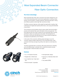
Cable Layout:
CA-D9M-X3F-L-A_02
Length in Feet
P1
Assembly Notes:
(1) P1: Use male. metal, DB-9 connector.
Connector to include backshell and male
screwlock assembly
(2) P2: Use Female, 3 Pin, In-Line XLR
connector
(3) Use high quality, low capacitence,
individually shielded twisted pair audio cable
Belden 1508A or equivalent.
(4) Twisted pair configuration as shown.
(5) Tie and solder all shields to P1 connector
case and to P2 pin 1.
Wiring Information:
Audio In, Hi
Audio In, Lo
P1
P2
4
9
2
3
Mic In, Hi
Mic In, Lo
1
Shield
Notes:
(6) This drawing identifies configurations for
RIU to XLR 3 pin female audio interface
cable. This would typically (but not
exclusively mate with a microphone.
Pins Not Shown are
Unused
Rev
Date
Originator
Description
-
2-15-00
NKW
Original Release
02
04-03-09
CJA
Added Information Table and Converted to Graffle
ADVANCED SIMULATION TECHNOLOGY inc.
500A Huntmar Park Drive, Herndon, VA 20170
www.asti-usa.com
Cage Code
Title
Dwg #
Sheet
OVFW3
Audio Interface Cable - RIU to 3-pin Female XLR
CA-D9M-X3F-L-A_02
1 of 1
Industry
connector Sub
Group
ASTi Part
Number Sub
Group
DB9
D9*
Source
Device
ASTi Part Number
RIU, ACE-RIU CA-D9M-X3F-L-A
Current
Revision
Number
02
Description & Case Use
Special Notes
© Copyright 2026 Paperzz