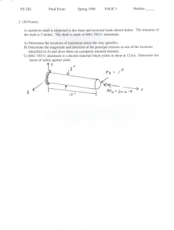
Equilibrium of Deformable Body Review – Static Equilibrium If a body is in static equilibrium under the action applied external forces, the Newton’s Second Law provides us six scalar equations of equilibrium F 0; F 0; Fz 0 M 0; M 0; M 0 x y x y z •The sum of all the forces in x, y, and z coordinate directions are zero •The sum of moments of all the forces about axes x,y, and z are zero Considering Static Equilibrium of the element, we have * Normal and shear stress components p actingg on opposite pp sides of an element must be equal in magnitude and opposite in direction * Shear stress components satisfy moment equilibrium xy yx ; xz zx ; yz zy PRINCIPAL STRESSES State of stress at a point in a material is completely defined by the stresses acting on the planes of a cubical volume element whose edges are parallel to coordinate directions. Often,, it is important p to determine the state of stress on a pplane at some angle to the coordinate axes. Mostly, the state of stress on a plane on which no shear stresses act is important for design purposes. purposes A plane, where no shear stresses act is called a principal plane and the normal stress that acts on such a plane is called principal stress. Mohr’s Circle - Its Use and Limitations Consider a stress state at a point is such that on one of the coordinate plane, there are no shear stresses and only normal stress (may be zero or not) is present. That normal stress is one off the th principal i i l stress t as shown h i figure. in fi You can see that on an plane perpendicular to z-axis only sz ( may be tensile, compressive or zero) is present. Then remaining two principal p c p stresses s esses ccan be de determined e ed us using g bbiaxial sstress ess field e d and d Mohr Circle. Biaxial stress field in xy-plane can be shown as above. Using stress transformation equation, the normal stress x along x axis and xy the shear stress (from last terms Mech. Mech Of solids) can be written as. 1 x y 12 x y cos 2 xy sini 2 2 1 xy x y sin 2 xy cos 2 2 x (A) x will become principal stress if xy= 0. Using this condition, the remaining principal stresses can be determined as. p 1 1 x y 2 2 y xy2 2 x and the orientation of the principal planes with respect to xaxis is given by tan 2 2 xy x y The same results can be expressed graphically using Mohr’s Circle. Rearranging g g the equations q (A), ( ), we obtain 1 1 x 2 x y 2 x y cos 2 xy sin 2 1 xy x y sin 2 xy cos 2 2 Squaring the above equations, then adding, gives 2 2 1 1 2 2 x 2 x y xy 2 x y xy This is the equation of a circle whose center is at 1/ 2 2 andd whose h radius di is i given i by b 1 2 1 2 x y ,0 x y xy 2 Every point on the circle defines the stress state acting on planes at any angle q from the original x or y axis. For the correct construction of Mohr’s circle, certain rules are followed and a consistent handling of positive and negative stress is essential, only if proper orientation of planes is desired. No such concern is required q if only y the magnitudes g of the p principal p stresses are sought. Although various conventions are in use, we follow the convention given in Hibbler’ Book. 1.Normal stresses are plotted to scale along the abscissa (horizontal axis) with tensile stresses considered positive and compressive stresses negative. 2.Shear stresses are plotted along the ordinate (vertical axis) with positive direction downward to the same scale as used for normal stresses. A shear stress that would tend to cause counter-clock wise rotation of the stress element in the physical plane is considered positive while negative shear stress tend to cause clockwise rotation. 3.Angle between lines of direction on the Mohr plot are twice the indicated angle g on the physical p y plane. p The angle ‘2' on the Mohr circle is measured in the same direction as the angle for the orientation of the plane in physical plane. According definition, the values of corresponding to the points D and B (where = 0) are the principal stresses. The radius of the Mohr’s circle gives the maximum in-plane shear stress Three -Dimensional Mohr’s Plot • As mentioned previously, Mohr’s circle can be drawn to determine principal stresses only if one of the three principal stresses is known. • Since the known principal stress is also a normal stress, it can be plotted on s axis and circles can be drawn between all the principal stresses as shown. then the maximum absolute shear stress is equal to radius of largest Mohr’s circle. Absolute maximum shear stress is given as max 1 pmax p min 2 Static Failure Theories x M *(d / 2) M *(d / 2) 32 M 32*6000 18108lb / in 2 4 3 3 d / 64 d *(1.5) I zx Tr T (d / 2) 16T 16*8000 48288lb / in 2 4 3 3 J ( d / 32)) d (1.5) ( ) v 4V 4V 4*1000 754.5lb / in 2 2 2 3 A 3( d / 4) 33*(( *(1.5) (1.5) / 4) At Point A z 1, 2 x 2 x z 2 2 xz 58184, 40076lb / in 2 max 49130lb / in 2 2 At point B xy 48288 754 49042lb / in 2 1 , 2 49042lb / in 2 max 49042lb / in 2
© Copyright 2026 Paperzz