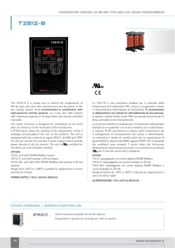
FACOLTA’ DI INGEGNERIA DELL’UNIVERSITA’ DEGLI
STUDI ROMA III
Laurea magistrale in Ingegneria Civile per la Protezione dai
Rischi Naturali (Dm 270)
Corso di costruzioni in zona simica
Modulo di SISMOLOGIA
F.Sabetta
3. Propagazione delle onde sismiche
Faglie
Meccanismi focali
Anno accademico 2011/12
Corso di sismologia
3.- Propag onde, Faglie, meccanismi focali
Dispersion and Energy......................................................................................................... 3
Phase and Group velocity ................................................................................................ 3
Energy of waves............................................................................................................... 3
Geometrical spreading and anelastic attenuation................................................................ 4
Ray theory ........................................................................................................................... 5
Reflection and refraction of seismic waves.......................................................................... 6
Snell’s law ........................................................................................................................ 6
Seismic waves inside the earth............................................................................................ 8
Fault ruptures....................................................................................................................... 9
Fault geometry ..................................................................................................................... 9
Classification of fault ruptures............................................................................................ 10
Seismic Source .................................................................................................................. 12
Double couple model ......................................................................................................... 13
Radiation pattern................................................................................................................ 14
Seismic moment ................................................................................................................ 14
Centroid Moment Tensor................................................................................................ 15
Fault plane solution (focal mechanism) ............................................................................. 15
Beach Balls .................................................................................................................... 17
F. Sabetta 3.2
Corso di sismologia
3.- Propag onde, Faglie, meccanismi focali
Dispersion and Energy
Phase and Group velocity
from Telford- 1990
The increase in velocity of surface waves
with wavelenght constitutes dispersion. In
this case is necessary to distinguish
between the phase and group velocity.
Phase velocity is the distance travelled
per unit time by a point of constant phase
such as a peak or trough.
This is not the same as the speed of a
pulse of energy which is the group
velocity U(λ).
When waves of different frequencies are
generated,
the wave disturbances
interfere producing
destructive and
constructive patterns. The latter behave as
wave packets and propagate with group
velocity depending on the variation of
phase velocity with wavelenght
U =V −λ
Individual crests and troughs travel through the group
appearing at the tail of the train and disappearing at its
head so that their speed V is higher than U
dV
dλ
When V increases with wavelenght,
as normally in the earth, U<V
Energy of waves
Consider a spherical wave for which the radial displacement, for a fixed value of
r, is given by u(t) = A cos(ωt+φ)
The kinetic energy per unit volume is
2
1 ⎛ ∂u ⎞
1
ρ ⎜ ⎟ = ρω 2 A2 sin 2 (ωt + φ )
2 ⎝ ∂t ⎠
2
Considering the harmonic balance between kinetic and potential energy, the
energy density E of a wave is given by
E=
1
ρω 2 A2 = ρ 2π 2 f 2 A2
2
The energy density is proportional to the first power of the density of the medium and
to the second power of the frequency and amplitude of the wave
F. Sabetta 3.3
Corso di sismologia
3.- Propag onde, Faglie, meccanismi focali
Geometrical spreading and anelastic attenuation
The real Earth is not perfectly elastic and waves attenuate with distance due to various
energy-loss mechanisms. The attenuation can be attributed to 2 main sources:
•
•
Geometry of wave propagation
Materials through which the the waves travel
GEOMETRICAL SPREADING
ANELASTIC ATTENUATION
GEOMETRICAL SPREADING
When earthquake energy is released from a fault below the ground
surface, body waves travel away in all directions. If the rupture zone can
be represented as a point source, the wavefronts will be spherical and the
energy will be distributed over surfaces increasing as the square of the
distance from the source. So the geometrical spreading causes the
2
energy to decrease as 1/r and the amplitude as 1/r
r1
r2
In case of surface waves the energy will be distributed over circles
increasing as the first power of the distance. So the geometrical
spreading causes the energy to decrease as 1/r and the
amplitude as 1/√r. In other words, surface waves attenuate
(geometrically) much more slowly than body waves. This explains
the greater proportion of surface wave motion that is commonly
observed at large epicentral distances (>100 km).
ABSORPTION OR ANELASTIC ATTENUATION
As the wave propagates, the elastic energy is gradually absorbed by the medium and
reappears ultimately in the form of heat as all the natural processes involving internal
friction: This process is called absorption or anelastic attenuation and is responsible for
the eventual complete disappearance of the wave motion. Besides internal friction other
mechanisms contribute to energy loss (piezoelectric and thermoelectric effects, viscous losses
in the fluids filling the rock pores, etc.). The anelastic attenuation is exponential with the
traveled distance r :
-ηr
A=A0 e , where η is the friction coefficient.
Anelastic attenuation in seismology is usually parametrized with the introduction of the
quality factor Q defined in terms of the fractional loss of energy per cycle of oscillation
1
ΔE λη
=−
=
π
Q
2πE
Where ΔE is the loss of elastic energy per wave cycle
and E is the peak elastic energy reached in that cycle
πr
πfr
−
λ
Q
A = Ao e
= Ao e vQ
−
For a constant value of Q high frequency waves attenuate more rapidly than low
frequency waves because, for a given distance, they will go through more oscillations
F. Sabetta 3.4
Corso di sismologia
3.- Propag onde, Faglie, meccanismi focali
In general Q increases with material density
and velocity. Large values of Q imply small
attenuation; as Q approaches to zero
attenuation is very strong.
Q is largely independent of frequency in
the range from 0.001 to 1 Hz.
At higher frequencies Q increases
with frequency Q=Q0fn
Where Q0 is Q at 1 Hz and n varies
from 0 to 1
Ao
r
A
A= o
r
A=
A = A oe
Body waves
GEOMETRICAL SPREADING
Surface waves
πr
λQ
-
= A oe
πfr
vQ
ANELASTIC ATTENUATION
Ray theory
Fermat’s principle defines the propagation time of a seismic wave between
two points A and B as the minimum travel time along any continuous path
connecting A and B. The path producing the minimum travel is called ray path
and its direction is represented by a vector called a ray. A wavefront is defined
as a surface of equal travel time and the the rays are perpendicular to the
wavefront pointing in the direction of propagation.
A beam of light is refracted or
reflected when it crosses the
boundary between air and water.
Seismic waves behave similarly at
boundaries within the Earth.
Complex wave phenomena such as reflection, refraction, wave type conversion, and diffraction take place
in an inhomogeneous medium as the Earth. Rays provide a very useful mean of tracking an expanding
wavefront giving an intuitive framework for extending elastic wave solutions from homogeneous to
inhomogeneous materials. The fact that the Earth’s inhomogeneity is primarily one-dimensional (i.e.
varies with depth) simplifies the situation: seismic waves behave very much as light does. This leads to
many parallels with optics and to approximate the wave equation solutions with the ray behaviour.
These approximations are collectively known as geometric ray theory
F. Sabetta 3.5
Corso di sismologia
3.- Propag onde, Faglie, meccanismi focali
In classical optics the geometry of a wavefront is governed by Huygens’ principle, which
states that every point can be considered the source of a small secondary wavelet travelling
with the velocity of the medium at that point. Portions of the w.f. which are located in high
velocity material produce wavelets that travel farther than those produced by points in
relatively low-velocity material. This causes a spatial dependence in the shape of the w.f.
Because rays are the normals to the wavefronts, rays will also change direction according to
the material wave velocity.
from Lay and Wallace, 1995; Kramer 1996; Press and Siever 1994.
Reflection and refraction of seismic waves
Snell’s law
Whenever a wave encounters an abrupt change in the elastic properties, part of the energy is
reflected and part is refracted into the other medium with an abrupt change in the direction of
propagation. Willebrod Snell (1591-1626) considered the change of direction of ray paths at
interfaces between materials with different wave velocities and, using Fermat’s principle, showed
that:
sin i / v = constant = p
where i is the angle between the ray path and the normal to the interface, v is the wave velocity
and p is called the ray parameter or horizontal slowness.
This relationship holds for both reflected and transmitted waves. It indicates that the
transmitted wave will be refracted (except when i=0) when the wave velocities are different on
each side of the interface. As a ray enters material of increasing velocity the ray is
deflected from the vertical.
sin(i) α1
=
sin(τ ) α2
F. Sabetta 3.6
Corso di sismologia
3.- Propag onde, Faglie, meccanismi focali
Seismic rays behaviour in a layered medium where velocity increases with depth
Ray curvature due to increasing velocity with
depth
from Lay and Wallace, 1995 and Kramer 1996.
Reflected an refracted rays
resulting from incident P, SV and
SH waves
Since incident P and SV waves involve particle motion perpendicular to the plane of the
interface they will each produce both reflected and refracted P and SV waves.
An incident SH wave doesn’t involve motion perpendicular to the interface and only SH waves
are reflected and refracted.
F. Sabetta 3.7
Corso di sismologia
3.- Propag onde, Faglie, meccanismi focali
Seismic waves inside the earth
The possible types of waves may be classified
by the number of reflections along the path.
In general the various wave groups on
seismograms represent different combinations
of reflections and refractions: each one is
denoted by a particular combination of letters
which stand for successive segments of the ray
from source to station.
The type of wave is indicated by P and S in the
mantle, by K in the outer core, and by I (P) or
J (S) in the inner core. Reflection at the
surface is indicated as PP or SS; reflection
at the outer core’s surface is shown by
interposing the letter c as PcP ScS.
from Press and Siever, 1994
F. Sabetta 3.8
Corso di sismologia
3.- Propag onde, Faglie, meccanismi focali
Fault ruptures
earthquake is caused by a rupture on a geological fault, the dimensions of which may be tens or
even hundreds of kilometres. In reality the fault ruptures associated with earthquakes are often
very complex but it is usual to model the fault rupture as a rectangular plane.
For non vertical faults the lower block is termed footwall and upper block is termed hangingwall.
The geometry of a fault is defined by its surface orientation, its dip and its down-dip extent.
Seismicity data such as focal mechanisms can provide constraints on dip and down-dip
seismogenic extent defining width, which, along with fault length, are key parameters for
quantifying the fault area that is used to estimate magnitude and seismic moment.
Fault geometry
The fault plane is defined by:
strike φ, the angle made by the line of
intersection between the fault plane and
the
ground
surface,
measured
clockwise from north in the horizontal
plane
dip δ, the angle of the maximum slope
of the fault plane, measured from the
horizontal in the vertical plane
Rak
rake λ, the angle between the strike
direction and the vector of slip of the
hanging wall with respect to the fault
wall. It is measured in the plane of the
fault, positive upwards. A normal fault Illustration of the definition of the dip (δ), strike (φ)
rupture has a rake of –90° and a and rake (λ) of a fault rupture (Shearer, 1999)
reverse rupture a rake of +90°.
F. Sabetta 3.9
Corso di sismologia
3.- Propag onde, Faglie, meccanismi focali
DEFINITIONS
FAULT - a fracture surface along
which appreciable displacement has
taken place
SLIP - the relative movement on a
fault measured from one block to the
other as the displacement of formerly
adjacent points.
HANGING-WALL BLOCK - the body
immediately above a non-vertical
fault
FOOT-WALL BLOCK - the body
immediately below a non-vertical fault
The rupture begins at one particular point
and then propagates along the fault plane
very rapidly: average velocities of rupture
are between 2 and 3 km/s.
Classification of fault ruptures
If the movement on the fault is purely vertical the rupture is referred to as dip-slip,
which may be either normal (hanging wall moves downwards) or reverse
(hanging wall moves upwards). Reverse faults with shallow angles of dip (less
than about 30°) are known as thrust faults
R. Butler : http://earth.leeds.ac.uk/faults/
F. Sabetta 3.10
Corso di sismologia
Puts younger rocks on
top of older rocks
3.- Propag onde, Faglie, meccanismi focali
Puts older rocks on
top of younger rocks
Ruptures involving only horizontal slip are called strike-slip faults and these are
classified as either right-lateral (dextral) or left-lateral (sinistral). Many faults show a
combination of both horizontal and vertical slip and these are known as oblique
ruptures
R. Butler : http://earth.leeds.ac.uk/faults/
F. Sabetta 3.11
Corso di sismologia
3.- Propag onde, Faglie, meccanismi focali
L= Fault Rupture Length
W= Fault Rupture width
Strike = azimuth clockwise from the north
Dip= angle of the fault plane
Rake = angle measured on the fault plane
strike direction to the average slip direction
0o <= strike <= 360o
0o <= Dip <= 90o.
counterclockwise from the reference
-180o <= Rake <= 180o
North
Strike
Strike direction
Depth to
Top of Rupture
Slip direction
Dip
Dip direction
Rake
W
L
Seismic Source
The sliding motions initiate at a point - hypocenter - and a slip front expands
outward over the fault, separating regions that are slipping from regions that
have not yet slipped.
Stored elastic energy in
the source
is
released
focu
heat
seismic
waves
slip
F. Sabetta 3.12
Corso di sismologia
3.- Propag onde, Faglie, meccanismi focali
Double couple model
Internal forces resulting from a stress release on a fault must act in opposing directions so as to
conserve momentum. For example we can have two force vectors pointing in opposite directions
separated by a distance d. If the distance d is perpendicular to the force orientation, the angular
momentum is not conserved unless there also exists a complementary couple that balances the
forces. The resulting pair of couples is termed a double couple.
The simplest physical model for the forces acting at a point that are compatible
with the shear dislocation that causes an earthquake is called a double couple,
consisting of two perpendicular pairs of forces acting in opposite directions.
Double couple model (left) for
forces acting on a shear
dislocation,
and
the
compatible system of dipoles
(right). (Shearer, 1999)
The same displacement field (measured by seismographs) can be generated
both by the couple acting in X1 and X2 direction so that the fault plane could
be either X1 ( strike-slip right lateral EW) or X2 (left lateral NS).
• Both
fault planes are consistent with
observations in the double-couple model.
distant
seismic
• The real fault plane is termed the primary fault plane; the other
is termed the auxiliary fault plane.
• Both planes produce
displacement in the far field.
exactly
the
same
seismic
• Distinguishing
between the primary and auxiliary fault planes
requires the use of further information such as aftershocks
locations or observed surface rupture or known patterns of
faulting in the region.
F. Sabetta 3.13
Corso di sismologia
3.- Propag onde, Faglie, meccanismi focali
Radiation pattern
Max S wave
No P wave
1
Max P wave
No S wave
2
At station 1 and 5, positioned in the strike direction of
the fault, the opposite signs of motion on both side of
the fault will cancel. No P wave will be observed. The
latter also applied for station 3. Stations 2 and 4 will
record the P-wave motions with the maximum
amplitudes but opposite sign.
3
4
5
P Wave
radiation
pattern
The radiation pattern is a geometric description
of the amplitude and sense of initial motion
distributed over the P and S wavefronts in the
vicinity of a source.
S Wave
radiation
pattern
Displacement field
generated by a double
couple (strike-slip right
lateral EW or left lateral
NS).
Seismic moment
Is the best measure available of the absolute size of an earthquake and is the
resultant moment of the body forces producing the same displacement field
resulting from the dislocation on the fault.
The seismic moment may be considered to be a measure of the work done in
rupturing the fault and moving the surrounding volume of the crust.
M0 = μ Δu A
scalar
in SI units is given in N·m
in c.g.s. units is given in dyne·cm
1 N·m = 10 7 dyne·cm
where:
Δu is slip vector or average final static displacement after the rupture (m)
A is the fault area of the rupture (m 2)
μ is the rigidity of the Earth’s crust, usually taken to be about 3 x 10 10 N/m2=
30 GPa =300 Kbar
It is generally not calculated from field measurements, but rather it is
determined from seismograms. This can be done either from body-wave
modeling or from the centroid moment tensor solution (CMT).
F. Sabetta 3.14
Corso di sismologia
3.- Propag onde, Faglie, meccanismi focali
Centroid Moment Tensor
The CMT is the most complete
description of the forces acting on the
seismic source and is represented by
a 3 x 3 matrix of second order
tensors, the first subscript referring to
the direction of action of the force and
the second to the moment-arm axis .
In the case of a double couple, which
corresponds to pure shear with no
change in volume, the leading
diagonal of the CMT matrix is zero
and the off-diagonal elements are
symmetrical.
The CMT provides not only a measure of the
seismic moment of the earthquake but also a
fault plane solution.
Since 1977 Harvard University has
routinely calculated CMT moments
and
fault
plane
solutions
for
earthquakes of magnitude 5.5 and
greater, and the catalogue of these
solutions can be accessed via Internet:
http://www.globalcmt.org/CMTsearch.h
tml
Fault plane solution (focal mechanism)
By observing the sense of the first motions of P-waves at many stations in
different azimuth with respect to the source it will be possible to deduce a “fault
plane solution”. Because of the symmetry of the first-motion patterns two
potential rupture planes (nodal planes) perpendicular to each other can be
constructed.
T axis
+
_
_
P axis
+
Examples of first P-wave arrival polarities for rays
leaving from different quadrants of the seismic
source.
Radiation pattern, quadrant of compression and
dilatation, and Tension and Pressure axis from a
a double couple of forces (left lateral EW strikeslip / right lateral NS)
F. Sabetta 3.15
Corso di sismologia
3.- Propag onde, Faglie, meccanismi focali
Focal
sphere
If a small sphere is drawn around the focus of the earthquake, each ray will pass
through a unique point on the surface of the sphere. Two perpendicular planes can
be constructed that pass through the focus at the centre of the sphere and which
on the surface will define four different quadrants, two of compression and
two of dilatation, which are usually shaded grey and left blank respectively.
If P-wave polarity readings from relatively close seismic stations are disregarded,
then all of the rays will pass through the lower half of the sphere. It is then a
simple matter to project the lower hemisphere onto a two-dimensional image
that represents the focal mechanism of the earthquake.
Lower hemispherical projection for a pure
strike-slip rupture on a fault oriented either NS or E-W (Reiter, 1990). The dots represent
the points of departure of the rays that carried
the first P-wave arrivals to seismograph
stations at which their polarities (solid circles –
compression, open circles – dilatation) were
read.
From these ‘beach balls’ the strike, dip and
rake can be read from the projections of the
two perpendicular planes, one of which will
correspond to the actual fault rupture plane,
the other being known as the auxiliary plane.
It is not important for engineers to know the
details of how to obtain a lower-hemispherical
projection for a fault plane solution. It is
important, however, to be able to recognise
immediately the type of fault rupture
mechanism from the projections
F. Sabetta 3.16
Corso di sismologia
3.- Propag onde, Faglie, meccanismi focali
Beach Balls
Shaded regions represent Pwaves leaving downward
from the source with upward
first motions at the receivers,
while the unshaded regions
will result in downward first
motions at the receiver.
The tension axis is in the
middle of the shaded region;
the pressure axis is in the
unshaded region.
Typical fault plane solution ‘beach balls’ for different
rupture mechanisms (Reiter, 1990).
Fault plane solutions for major earthquakes
(m>5) in Italy from 1977 to 1992.
F. Sabetta 3.17
Corso di sismologia
3.- Propag onde, Faglie, meccanismi focali
Fault plane solution - terremoto dell’Aquila 06-04-2009
CENTRAL ITALY L’Aquila
Harvard Global
Date: 2009/ 4/ 6 Centroid Time: 1:32:49.5 GMT
CMT catalog
Lat= 42.33 Lon= 13.32
Depth= 12.0 Half duration= 3.4
Centroid time minus hypocenter time: 7.5
Moment Tensor: Expo=25 -3.180 1.170 2.010 -0.903 -0.218 -1.760
Mw = 6.3 mb = 6.3 Ms = 6.3
Scalar Moment = 3.42e+25
Fault plane: strike=336 dip=43 slip=-68
Fault plane: strike=127 dip=50 slip=-109
Soluzione
determinata con i dati
della rete sismica
MedNet e di altre reti
europee utilizzando
la tecnica dei
Regional Centroid
Moment Tensors (si
veda
http://www.bo.ingv.it/
RCMT).
terremoto del Giappone 11/03/2011
Scheme of the Eurasia-Philippine Sea-Pacific triple point
Source: Modified from: L. Jolivet, ISTO, Orléans, France
The Philippine Sea Plate, supporting the Bonin Arc, dives beneath the Eurasian plate at
the Nankai Trench.
The Pacific plate dives under the two previous plates in the Japan and Bonin Trenchs.
http://www.emsc-csem.org/Page/index.php?id=196 EMSC
F. Sabetta 3.18
Corso di sismologia
3.- Propag onde, Faglie, meccanismi focali
Fault plane solution - terremoto del Giappone 11/03/2011
USGS
Harvard Global CMT catalog
F. Sabetta 3.19
© Copyright 2026 Paperzz