Title
Author(s)
Citation
Issue Date
Doc URL
Finite-element solution of anisotropic waveguides with arbitrary tensor permittivity
Koshiba, M.; Hayata, K.; Suzuki, M.
Journal of Lightwave Technology, 4(2): 121-126
1986-02
http://hdl.handle.net/2115/6085
Right
©1986 IEEE. Personal use of this material is permitted. However, permission to reprint/republish this
material for advertising or promotional purposes or for creating new collective works for resale or
redistribution to servers or lists, or to reuse any copyrighted component of this work in other works
must be obtained from the IEEE.
IEEE, Journal of Lightwave Technology, 4(2), 1986, p121-126
Type
article
File Information
JLT4_2.pdf
Instructions for use
Hokkaido University Collection of Scholarly and Academic Papers : HUSCAP
-
JOURNAL- OF LIG HTWAVE TECHNOLOGY, VOL. LT· 4, NO.2, FEBRUARY 1986
121
Finite-Element Solution of Anisotropic Waveguides
with Arbitrary Tensor Permittivity
MASANORI KOSHIBA , SEN IOR MEMB ER, IEEE, KAZUY A HAYAT A,
MICHIO SUZUKI . SENIO R MEMBER, IEEE
AbSfract - An improved vector finlte-element method has been used
for the solution of general anisotropic waveguide problems. This
method Is formulated in terms of all three components of the magnetic
field lind Is "alld for arbitrary tenso r permittivity . In the improved
fi nile-eiement anal ysis, the spurious nonphysical solutions do not a ppear when the effective rdractlve index is la rger Ihan I. The~ron' ,
Ibis method is very useful for the analysis of the s urface· wave modes
of optical waveguides. To show th e validity and usefulness of the improved finite-element method, computed results art illustrated Tor an\5otrOI)lc rectangular waveguides with optic axis in any orientation and
IYrotroplc rectangular waveguides.
II . F] N]TE- E LEMENT METH OD
A va riational express ion with the divergence-free constraint (V . H = 0) wh ich is imposed in a least-square
sense is known to be [1 0]- [16]
t ~
En
(V X H )' . ([Kr ' V
I . I NTROD UCTION
A
VECTOR finite-element method in an axial -compoJ-\.nent (E~-Hz) fonnulation [1] - [7] or in a three-component (the magnetic field H) formulation [8] , [9] is
widely used for the analysis of optical waveguides [2] [4], [6} , [7], [9]. The most serious difficulty in using the
vector finite-element analysis is the appearance of the
spurious nonphysical solutions [1], [S] - {9]. Recently, an
improved finite-element method has been formulated in
tenns o f all three components of H {1O] - [lS] . In this improved H-field formulation , the spurious solutions do not
appear when the effective refractive index tJlko is larger
than 1 [14], {IS]. where ko is the wavenumber of free
.. space and fJ is the phase constant in the direction (z axis)
of propagation . Therefore, this method is very useful for
the analysis of the surface-wave modes of optical waveguides which correspond to the solutions in the region f31
ko <::: l. In addition , the H-field formulati on is valid for
general anisotropic problems. However, in {IO]- [15] , an
isotropic dielectric wavegu ide is mainly studied and the
application of the H-fi eld fonnulation is restricted to an
anisotropic dielectric waveguide composed of a uniaxial
material whose optic ax is lies in the plane (xy-plane) perpendicular to the 1. axis [10], [13], [IS] .
~ In this paper, to show the validity and usefulness of the
Improved H-field formulation for a variety of anisotropic
waveguides, computed results are illustrated for anisotropic rectangular waveguides with optic axis in any orientation and gyrotropic rectangular waveguides.
ManUSCript received March 18, ]985; revised June], 1985.
q .Tht authors are with the Depanment of Electronic En gineering, HokIda Univers ity, Sapporo, 060 Japa n.
]EEE LoS Number 8406199.
AN D
+
x
H ) d!J
jL
(V . H )' (V . H ) d!J
(I)
where 0 represents the cross section of a waveguide, the
asterisk denotes a complex conjugate , and the relative
pennittivity tensor [K] is given by
Ken Kry K:'x
[KJ -
K!y Kyy
Ku;
Kyz
(2)
K j. Ku.
Here [ .] denotes a matrix . As we consider loss-free materials, [K] is Hennitian. In anisotropic dielectric cases,
all elements of [KJ are real so that [K] is a real symmetric
matrix [1 7]. In gy rotropic cases , diagonal elements of [K]
are real, whereas off-diagonal ones in general are compl ex
{1 7]. The fonn er corresponds to material s with crystalline
anisotropy or electrooptic cases , while the latter corresponds to the magnetooptic case [17].
Dividing the cross section 0 of the waveguide into a
number of second-order triangular elements in Fig. I , the
magnetic fields Hz, Hy, and Hl within each element are
defined in tenns of the magnetic fi elds at the corner and
midside nodal points:
H, ~ (N) ' (H,), exp (-j~,)
(3)
H, ~ (N )' (H,), exp (-j~,)
(4)
H, ~ j (N )'( H, ), exp (-j~,)
(5)
where {Hz }(' {Hy }t' and { H~ } t are magnetic field vectors
corresponding to the nodal points within each element,
{N} is the shape function vector [10] , [15] , and T, {.} ,
and { . }T denote a transpose, a column vector, and a row
0733-8724/86/0200-0121 $0 1. 00 © 1986 IEEE
,j
,
JOUR NAL OF LIGHTWAVE TECHNOLOGY. VOL. LT·.( NO. 2. FEBRUARY 1986 1
122
,.,
%·)1
•
•
,
••
;
,
,·
•
•
•
,,
"
j
.~
,,
-~
1
""'-;,:-L-""'
!.osoi;-- .....
"
"
,j
.j
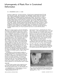
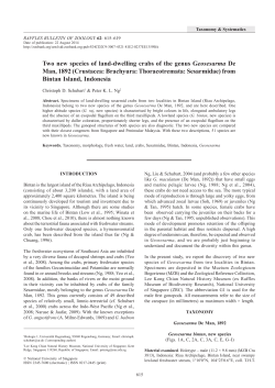
Fig. 2. Dispersion characteristics of an anisotropic rectangula r wave-,'j'
guide. Solid li nes. circles, and dots represent the solutions of (6) . the
resul ts of the variational method \20). and the solutio ns of (7). respcc:_~
tively.
j
•
Fig. I . Finite-cleme nt division of an anisotropic rectangular waveguide or
a gyrotropic rectangular waveguide.
~
where the boundaries AB, Be, CD, and DA are assumed)
to be perfect electric conductors [15]. The convergence]
of the solution is checked by moving these conducto ~
gradually away from a core region.
vector, respectively. Variation of (I ) with respect to the
nodal variables leads to the following eigenvalue problem:
A. Anisotropic Rectangular Waveguides
([S]
+
[Un {H} - kilT] {H} ~ {OJ
(6)
We consider an anisotropic rectangular waveguide,
where {H} is the nodal magnetic field vector, {O} is a composed of a uniaxial material surrounded by an iso1
null vector, [S1, [Tl. and [U] are the matrices related to tropic material of refractive index .J2.05, where the or-1
the first, second, and third tenns on the right-hand side of dinary and extraordinary refractive indices of a recta]<j
(1), respectively , and [T] is a real symmetric matrix . For gular core are .J2.31 and .J2.19, respectively .
Fig. 2 shows the dispersion characteristics of the anloss-free materials, [U] is a real symmetric matrix and [S]
is a complex Hennitian matrix. When Im(K"y) = Re(Kyz ) isotropic rectangular waveguide with W = 21 0whose optic'll
= Re(Kz,,) = 0, [S1 becomes a real symmetric matrix [8], axis c lies in the xy-plane at an angle 8 = 45 from {he
axis, where the whole region ABeD in Fig. 1 should b6j
[13J.
If the divergence-free constraint is neglected, the fol- divided into elements because of the lack of symmetry QL
the field. The solid lines in Fig. 2 represent the solutioi\S!
lowing eigenvalue equation is derived [8], [9], [18}:
of the improved finite-element program in (6). Compari~
[S] {H} - ki lT] {H} ~ {OJ .
(7) son of our results with the results of the variational methoW
In the earlier finite-element analysis using (7), the spu- [20] indicated by circles shows good agreement. This fa~
rious solutions appear and these solutions are scattered all demonstrates the reliability of the presem method. Th~
over the propagation diagram [8}-[ 16], [181.
dots in Fig. 2 represent the solutions of the earlier finile.~
In the improved finite-element analysis using (6), the element program in (7). It is found that when (7) is usi
appearance of the spurious solutions is limited to the re- numerous spurious solutions appear. The guided mode~;
gion {3/ko < 1 (14J, (15]. They do not appear when the of the waveguide in Fig. 2 can not be designated as E~
effective refractive index {3/~ is larger than 1. Therefore, or Ef,q because the main magnetic field component ofthesf
(6) is very useful for the analysis of the surface-wave guided modes is not H" or Hy [20].
,j
modes of optical waveguides which correspond to the soFigs. 3 and 4 show the dispersion characteristics of th~
lutions in the region {3/ko ;:: 1.
anisotropic square waveguides (W = t) whose optic axi~
lies in the xy-plane at an angle 8 from the x axis. Th~
waveguide with 8 = 0 0 in Fig. 3 has two planes of sym~
III . COMPUTED RESULTS
metry. Therefore, for the waveguide in Fig. 3, the regiorf
In this section, we present the computed results for an- AEIH in Fig . I is divided into elements. The E{ I and th~
isotropic rectangular waveguides and gyrotropic rectan- E11 modes in Fig. 3 are the fundamental and the firs~
gular waveguides . The guided modes are designated as higher-order modes, respectively. In an isotropic squartl
E~ or Ef,q [19]. The m~in field components of the E;'" waveguide, the E)I and the E11 modes are degenerai~,
modes are E" and Hy, while those of the E~q modes are Ey [19]. The propagation diagram of the waveguide with ~
and H" [19] _ A typical division of these waveguides into = 45 0 in Fig. 4 is very similar to that in Fig. 3. However~
second-order triangular elements is shown in Fig. I , the eigenvectors for the guided modes of the waveguid?
4
123
KOSHIBA It /II.: SOLUTION OF ANISOTROPIC WAVECiUlDES
'",.,
r:::~
,
•"
•-
,
... _----r - ------
-----f.. - - - - - - - ...
r-------... _-----
1,
~
j
"
W.,
------------------------------------------
.- --------- f..
f.- - - ------ -
•
.-
hIS '
,.)
"
".
,b)
Ei,
Erl
•
0
"
"
"
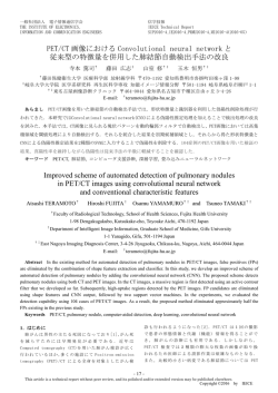
Fig. 3. Dispersion characteristics of an ani sotropic square waveguide with
'"
/
"" ""
/
/
'"
""///""'"
/////""/
/
the optic axis parallel to the x axis.
"'/// //'"
"'/""// /'"
2.3 1 , -- - - -_ _ _ _ _ _ _ _ _ _ _ _,
,
"
."-•
"
,
,,11'/1',,
,1' / / / 1 ' ,
, ///// ,
1'/ / / / / 1 '
1' / / / / / ,
, /////,
"1'1',1,,
,j
z~
1,
• • 4S·
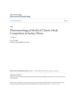
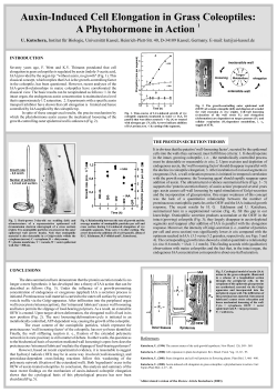
Fig. 5. Magne tic field ve ctor for the fundamental mode of anisotropi c
square waveguides wh ose optic axis lies in the xy·plane at an angle 6
from the x ax is. (a) 6 - 0· . (b) 6 - IS' . (cl 6 - 30'. (d) 6 = 45 " .
•
e.4S·
,
,
,,,r ,,
,r
,.,
"
Fig. 4. Dispe rs ion cha racteristics or an anisotropic square
whose optic uis lies in the xy-pla ne at an angl e (J
(d)
(0)
~.--,j
w. t.
8.30'
-
waveguide
45 · from the x uis.
r ,
r 1
,, I
I r
1
1 r
,
,
r 1
, ,, ,,,
1
I
I
I
1
I
I
I
I
I
1
1
I
I
I
1
1 r
,
.L,
•
,.,, ,
,
,\
\
\
\
\
\
,
\
\
\
\
\ \ \ \ \
\ \ \ \ \
\ \ \ \ \
\ \ \ \ \
\ \ \ \ \
\
\
\
\ \
\
,
\
,
\
\
,
8 0'S'
in Fig. 4 are different from those in Fig. 3. For the fun,b)
damemal and the fi rst higher-order modes, the variations
of the transverse components of the magnetic field vector
\ \ \ \ \
.... , ,
,
in a core-region with 8 are shown in Figs. 5 and 6, re\ \ \ \ \ \ \
'\ \
spectively, where /31 = 14 . The directions of the magnetic
....
\
\
field for the fundamental and the first higher-order modes
\
\ \ \ \ \
are almost parallel and almost nonnal to the optic axis,
\
\ \ \
\
respectively . Therefore, the guided modes of the wave\
\
....
guide in Fig . 4 can not be designated as E;" or Ef,., .
\
\ \
\
, .... .... .... ,
Figs. 7 and 8 show the dispersion characteristics of the
anisotropic square waveguides whose optic axis does not
8.4S·
lie in the xy-plane. The optic axis lies in the yz-plane at
• 1"30'
(d)
'01
~n angle 0 from the y ax is. The waveguide wilh 8 = 90°
tn Fig. 7 has two planes of symmetry, and therefore the Fig. 6. Magnetic fi eld vector for the first higher·orde r mode of anisotropic
squa re waveguides whose optic Bxis lies in the xy· plane at an angle 6
region AEIH in Fig . 1 is divided into elements. On the
fro:n the x axis. (a) 6 . 0". (b) (J - IS 9. (c) (J - 30 '. (d) 6 = 45" .
Other hand , the waveguide with 0 = 45° in Fig. 8 has one
plane of symmetry , and therefore the region AEFD in Fig .
I is div ided into elements. In the waveguide in Fig. 7, mode is the fundamental mode . The effect of the orien·
tation of the optic ax is is much stronger on the Erl mode
the Eil and the Er, modes are degenerate. When 9
9(}0, these modes are no longer degenerate and the E~l than the E~ I mode.
,
,
.kl
,
"*
,
,, , ,
,, , , , ,,
,, ,
,,,
,
""" " ,
, ,'"
, ,'" ,
,
",
,""
" " ,",
....
JOU RNAL OF LIGHTWAVE TECHNOLOGY, voL. LT·4. NO , 2, FEBRUARY
124
.,,-- - - - - - - ,
"'r------------------------------------,
"
II.. . Z . II ,.. . 11••• ]
_
r-.::"W ~.
-
I,
•
,
"
,
•
w.,
.
~ ",o
___ II,, 'J().S
_.- 11 ••• 1' _0
,
j
,
,.,
Fig. 7.
Di ~pcrsion
.'
,
"
(0)
characte ristics of an ani sotropic sq uare wllveguide with
the optic uis parallel to the l a:ds.
~ " . II ,, _ K ..
',.''r-------------------------------,
,
,.,
,
'.'
•
.J
-
11 , • • 0
---
K ,.,jO . ~
-- -
~ ,•
• jI-O
~l
'
~.--,j
•
w. ,. e •• ~ ·
"
Fig. 8. Dispersion characteristics of
'.'
.n anisotropic
e_
squa~
whose oplic ax i51ies in the Yl -plane al an angle
.,
(b)
waveguide
4So from the y axis.
B. Gyrotropic Rectangular Waveguides
We conside r a gyrotropic rectangular waveguide surrounded by air , where the relative pennittivity tensor of
the waveguide is given by
[KJ
~
Kn
0
0
-0
K."
K~
o
(8)
II ... ' . II ".~ ... ]
11, •• 0
• •• ~ , •• JO ' ~
,
,
K::' Ku,
Here Kyy = Ku, z:: 3 and Ky: is pure imag inary. This waveguide has one plane of symmetry, and the refore the region
AEFD in Fig. I is divided into elements.
Fig. 9 shows the dispersion characteristics of the gyrotropic square waveguides ( W = f). When Ku = 3 and
Ky~ = 0, the E11 and the E~I modes are degenerate. In
other cases, these modes are no longer degenerate. For
Ku = 2 (K;u < K.,., = Ku ) or K;u = 4 (Ku > K" = Ku ),
the fundamental mode is the E~I or the E11 mode , respectively . The effect of K;u is much stronger on the Eil mode
than the E ~l mode. In the Eil mode, the effective refractive indices fo r K,~
0 is larger than those fo r Ky: = O.
"*
•
,
"
(0)
.'
"
Fig. 9. Dispersion characteristics of gyrolropic square wa veguides. (0) .<.!
- 2. (b) K~ ~ 3. (c) K" _ 4.
In the E ~I mode, on the other hand , the effective indices for KYl
0 is smaller than those for K:p. except the higher frequency range for K;r;r = 4.
For the gyrotropic square waveguide with the off'-di
"*
KOS HlBA n 61.: SOLUTION OF ANI SOTROPIC WAVEGUIDES
agonal element Ku (Kxy = Ky, = 0), the region ABGH in
Fig. I is divided into elements. The dispersion curves fo r
the Eil or the Ef1 mode of this waveguide a re the same
as Ihose fo r Ihe Ef I or the £ 11 mode of the waveguide in
Fig. 9, respectively, where Ku , K"., and Kyt in Fig. 9
should be replaced by KY)" K",.. and K:.t , respecti vely.
For the gy rotropic square waveguide with the off-diagonal element K~'Y (Kyz = K u = 0) , the region ABeD in
Fig . I is di vided into element s. The guided modes of this
waveguide may not be designated as E~q o r Ef,q in the
same man ner as the cases of Figs. 2 and 4 .
In Figs. 3, 4 , and 7-9, the spurious solutions do not
appear because f3/ku > 1.
IV . C ONCL USIONS
Here we have shown the capability of the improved finite-element method in the three-component magnetic
field formulation · for solving general anisotropic waveguide probl ems. In this approach, the spurious solutions
do not appea r when the effective refractive index is larger
than 1. Therefore , this method is very useful for the analysis of the surface-wave modes of optical waveguides.
The vahdity of the method was con fi nned by comparing
numerical results for the anisotropic rectangular waveguide with th e results of the variational method . The numerical results fo r the anisotropic square waveguides and
the gyrotropic square waveguides were presented and the
propagati on characteristics of each wa veguide was discussed.
REF ERENCES
[II P. Daly , "' Hybrid·mode analysis of micromip by fi nite-element
metOOds, " IEEE Trans. MicroWlive 11rtory Tuhnol., vol. MTT -19.
pp. 19-2:5. Jan . 1971.
121 C. Yeh, S. 8 . Dong, and W. Olive r, "'Arbitrarily shaped inhomo.
ge neous oplical fibe r o r integrated optical wavegu ides." J. Appl.
PhY$., vol. 46, pp. 212:5- 2129, May 197:5 .
[31 P. Vandenbulcke and P. E. Lagasse, "Eigenmode analysis of aniso·
tropic optical fibres o r integrated optical waveguides," EIt!Clron . 1.£11. ,
vol. 12, pp. 120- 122, Mar. 1977.
[4) C. Yell, K. Ha, S. B. Do ng, an d W. P. Brown, "Single-mode optical
waveguides," Appl. Opl . , vo l. 18, pp. 1490- 1:504, May 1979 .
[5J M. Ikeuchi, H. Sawami, and H. Niki, "Analysis of open·type di ·
electric waveguides by tile fi nite·element iterative method," IEEE
TrailS. Microwa~ 11rtory Ttchnol., vol. MTT·29 , pp. 234-239. Mar.
1981.
[6) N. Mabaya, P. E. Lagasse, and P. Vandenbulcke, " Fini te element
analysis of o ptical waveguides." IEEE Tron$. MicroWll"'~ 11rtory
Tee/mol., vol . MTT·29. pp. 600- 60:5, June 1981.
[7J K. Oya mada and T . Okoshi, " T wo·dimensional fini le.element cal.
culation of propaga tion charac teristics of axially nonsymmet rical op.
tical fibers," Radio Sci., vol. 17, pp. 109- 116, Jan. - Feb. 1982.
181 A. Ko nrad, " High-order trian gular fini te clements for eleclromag.
netic waves in aniso trop ic media, " IEEE Trans. Microwave Theory
Tulmol., vol. MTT· 25, pp. 3:53- 360, May 1977.
[9] B. M. A. Rahman a nd J . B. Da vies, ' ·Finite· elemen t ana lysis ofoptical and microwave wavegui de problems." IEEE Trems. MicrOWlJIIt
Theory Technol., vol. MTT·32, pp. 20- 28. Ja n. 1984
[101 M. Koshiba, K. Hayata, and M. SUZUkI, "Veclorial finite·element
formulll1ion wit hou t spurious modes for dielec tric waveguides,"
TranI. In$l. EIUlroll . Commun. Eng . JapolI, vol. E67. pp. 191- 196,
Apr. 1984 .
[Ill M. Kosh iba , K. Hayata. and M. Suzu ki, "Vecto rial fin ile-e leme nt
method withou t spurious solu tions fo r dielectric waveguide problems," Elu/roll. ~II ., vol. 20 , pp. 409- 410, May 1984 .
[12) B. M. A. Rahman and J. B. Davies , " Pe nalty func lio n impro~ement
125
of waveguide solution by finite clements, " IEEE Trans. Micr01WJ1It
Th tory Tuhnol., vol. MIT·32 , pp. 922-928, Aug . 1984.
II3J B. M. A Rahman and J . B. Davies, " Fin ite·element solution of in·
tegnl1ed o plical waveguides. " 1. Ugh/Wli ve Ttchnol., vol. LT·2, pp.
682- 688 , ()(:1. 1984 .
114] M. Koshiba. K. Hayata, and M. Suzuki, "Study of spurious solulio ns
of finite·element me lhods in the three·component magnetic field formulation for dielectric waveguide problems," TrailS. 111M. Electron.
COll1mUII. Eng. h lpOII . vol. J67·B. pp. 1333-133g, Dec. 1984 (i n Jnp·
anese) .
115J M. Koshiba, K. Haya ta, a nd M. Suzu ki, " Improved fin ite· ele ment
formulation in terms of the magnetic· field vector for dielect ric wave·
guides," IEEE TrOllS. MicrOWllIIt 11reory Technol., vol. MIT·33,
pp. 227- 233, Mar. 19S:5 .
1I6] M. Hara, T. Wada. T. Fukasawa. and F. Kiku chi, "A three-dimen·
sional analy sis of RF elec tromagnetic field s by the fini te element
method." IEEE Tran$. Magn. , vol. MAG· 19, pp. 2417~2420, Nov.
1983 .
[17) S. Yamamoto. Y. Koyamada, and T. Mak imoto, " Normal· mode
analys is of anisotropic and gyrolropic thin·film waveguides for in te·
grllted o ptics:· J. Appl. PhY$., vol. 43, pp. 5090- :5097. Dec. 1972 .
[181 J. B. Davies, F. A. Ferna nd ez , Bnd G. Y. Philippou , " Finite element
analysi s of all modes in cav ities wi lh cireular symmetry,'· IEEE Tran.f.
Microw(J vt TI!eory Tech nol . . vol. MTT· 30, pp . 1975-1980, Nov.
1982.
[19] E. A. 1. Mareatili . . 'Die lectric rectangular waveguide and directio nal
coupler for integra ted optics." Bdl Sys/. Tech. J., vol. 48, pp. 2071 2102, Sept. 1969.
[201 M. Ohtaka, .. Analysis of the guided modes in the an isotropic dielectric Tl:Clangular waveguides. " Trans. IIw. Eltc/rot! . CQII1/11un. Eng.
Jllpon, vol. J64·C. pp. 674-6gl. Oct . 1981 (i n Japanese).
•
Masanori Kushiba (S M'84) was bo rn in Sapporo, Japan, on November 23, 1948. He received
the B.S. , M .S .. and Ph .D. degrees in electronic
e ngillCCring from Hok kaido Universi ly, Sa pporo,
Japan, in 197 1, 1973. and 1976, respectively.
In 1976, he joined the Depa rtmenl of Elec·
tronic Engineering, Kitami Institute of Technol·
ogy , Kitami, Japan . Since 1979, he has bee n an
Assistant Professor of Elec tronic Enginee ring at
Hok kaido Universi ly. He hu been e ngaged in reo
search on surface acoustic wav es, dielectric opti·
cal waveguides, and app lications of finite·element and bo und ary·demen1
methods to fie ld proble ms.
Dr. Koshiba is a member of the Institute of Electronics and Communi·
cation Engineers of Japan. the Institute of Televi sion Engineers of Japan,
the Institut e of Elec trical Engineers of lapan. tile hpan Society for Simu·
lat io n Tec hnology. and Japan Socie ty for Computat io nal Methods in En·
gmeenng.
•
Kazuya Hayata was born in Kushiro, Japan , on
December 1,1959. He received the B.S. and M.S.
degrees in electronic engineering from Hokkaido
Univers ity, Sapporo, Japan , in 1982 and 1984, reo
spectively.
Si nce 1984, he has been a Research Assistant
of Eleelronic Engineering at Hokkaido Uni ver·
sily. He has been engaged in researc h on dielee·
lric optical waveguides and surface acouslic
waves.
Mr. Hayata is a membe r of the Institute of
Eltetronics and Communication Engi neers of Japan.
-
126
JOURNAL OF LIGHTWAVE TEC HNO LOGY, VOt. , LT·4, NO , 2, FEBRUARY 1986"
Michl o Su:wki (SM'S7) was born in Sapporo, Japan, on November 14, 1923 . He received the B.S.
and Ph.D , degrees in electrical engineering from
Hokkaido Universit)'. Sapporo, Ja pan, in 1946 and
1960, respect ively.
From 1948 to 1962, he was an Assistant Pro fesoor o f Electrical Engineering Dt Hokkaido Uni-
versi ty. Since 1962, he has been a Professor of
Electron ic Engineerina at Hokkaido University .
From 1956 10 1957, he was a Research Associate
at the Microw ave Resea rch Insti tu te o f Polytechnic Institute of Brooklyn, Brooklyn, NY.
Dr. Su:tuki 15 a member o f the Institute of Electronics and Communi.
ca tion Engineers of Japan, the Inst itu te of Elec trical Enginee rs of Japan ,'
the Institute of Television Engineers of Japan, the Japan Society of Infor.~
malion and Communication Research, and the Japan Society for Simulation
Technology .
© Copyright 2026 Paperzz