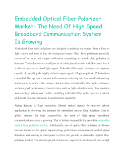
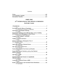
Electricity&Magnetism Lecture 24 Electricity & Magne/sm Lecture 24, Slide 1 Optics Kit Incandenscent Light Source Optics Bench Ray Table Component Holder Ray Table Slit Plate Component Holders (3) Slit Mask Parallel Ray Lens Ray Optics Mirror Cylindrical Lens Viewing Screen Lenses: 75, 150 and –150 mm focal lengths Convex/Concave Mirror (±50 mm) Crossed Arrow Target DIFFRACTION GRATING 5276 LINES/cm Colour Filters: red DIFFRACTION PLATE A B C D E blue-green Virtual Image Locators Diffraction Scale Polarizers Figure 1: Equipment included in the OS-8500 Introductory Optics System ........................... .. ..... ........................................ ..................... ..................... ..................... ..................... ..................... ..................... ..................... ..................... ..................... ..................... ..................... ..................... DIFFRACTION PLATE J I H G F green Variable Aperture Diffraction Grating Diffraction Plate Base Position Notch Figure 4: Component holder Variable Aperture Polarizer Lens or Mirror Figure 5: Using The Component Holder Top View So far we have considered plane waves that look like this: From now on just draw E and remember that B is s/ll there: Electricity & Magne/sm Lecture 24, Slide 3 Linear Polarization “I was a bit confused by the introduction of the "e-hat" vector (as in its purpose/usefulness)” Electricity & Magne/sm Lecture 24, Slide 4 Polarizer The molecular structure of a polarizer causes the component of the E field perpendicular to the Transmission Axis to be absorbed. Electricity & Magne/sm Lecture 24, Slide 5 Clicker Question The molecular structure of a polarizer causes the component of the E field perpendicular to the Transmission Axis to be absorbed. Eo Suppose we have a beam traveling in the + z direc/on. At t = 0 and z = 0, the electric field is aligned along the posi/ve x axis and has a magnitude equal to Eo y z What is the component of Eo along a direc/on in the x − y plane that makes an angle of θ with respect to the x − axis? C) 0 D) Eo/sinθ E) Eo/cosθ θ B) Eocosθ s co Eo A) Eosinθ Eo θ y Electricity & Magne/sm Lecture 24, Slide 6 “I can't believe your teaching us the law of "Malus"(Malice). I thought malice was to be avoided?” Electricity & Magne/sm Lecture 24, Slide 7 CheckPoint 2 Two Polarizers 60 45 30 15 0 1 The second polarizer is orthogonal to the first No light will come through. cos(90o) = 0 Electricity & Magne/sm Lecture 24, Slide 8 CheckPoint 4 Two Polarizers 80 60 40 20 0 1 Any non-‐horizontal polarizer aZer the first polarizer will produce polarized light at that angle Part of that light will make it through the horizontal polarizer Electricity & Magne/sm Lecture 24, Slide 9 There is no reason that φ has to be the same for Ex and Ey: Making φx different from φy causes circular or ellip/cal polariza/on: Example: At t = 0 RCP Electricity & Magne/sm Lecture 24, Slide 10 Q: How do we change the rela/ve phase between Ex and Ey? A: Birefringence By picking the right thickness we can change the rela/ve phase by exactly 90o. Right hand rule This changes linear to circular polariza/on and is called a quarter wave plate Electricity & Magne/sm Lecture 24, Slide 11 “talk something about intensity” NOTE: No Intensity is lost passing through the QWP ! BEFORE QWP: AFTER THE SAME! Electricity & Magne/sm Lecture 24, Slide 12 Right or Left? “red fox” got it? Right circularly polarized Do right hand rule Fingers along slow direc/on Cross into fast direc/on If thumb points in direc/on of propaga/on: RCP Electricity & Magne/sm Lecture 24, Slide 13 Circular Light on Linear Polarizer Q: What happens when circularly polarized light is put through a polarizer along the y (or x) axis ? A) I = 0 B) I = ½ I0 C) I = I0 X Half of before 1/2 Electricity & Magne/sm Lecture 24, Slide 14 CheckPoint 6 Case A Case B 50 38 Case A: Ex is absorbed Case B: 25 (Ex ,Ey) phase changed 13 0 1 Electricity & Magne/sm Lecture 24, Slide 15 Intensity: h i I = ✏0 c hE 2x i + hEy2 i SE A PH QW Plate CH AN GE Both Ex and Ey are s/ll there, so intensity is the same Electricity & Magne/sm Lecture 24, Slide 16 h i I = ✏0 c hE 2x i + hEy2 i RB O S AB Polarizer CO M PO NE NT Ex is missing, so intensity is lower Electricity & Magne/sm Lecture 24, Slide 17 CheckPoint 8 Case A A Case BB 40 30 RCP 1/4 λ Z 20 10 0 1 Electricity & Magne/sm Lecture 24, Slide 18 CheckPoint 10 Case A Case B 50 38 25 ½λ 13 Z Z 0 1 Electricity & Magne/sm Lecture 24, Slide 19 Executive Summary: Polarizers & QW Plates: Polarized Light Birefringence Circularly or Un-‐polarized Light RCP Electricity & Magne/sm Lecture 24, Slide 20 Demo What else can we put in there to change the polariza/on? Electricity & Magne/sm Lecture 24, Slide 21 Calculation Light is incident on two linear polarizers and a quarter wave plate (QWP) as shown. What is the intensity I3 in terms of I1? fast 45o y x w slo 60o I1 I2 I3 z Conceptual Analysis Linear Polarizers: absorbs E field component perpendicular to Transmission Axis (TA) Quarter Wave Plate: ShiZs phase of E field components in fast-‐slow direc/ons Strategic Analysis Determine state of polariza/on and intensity reduc/on aZer each object Mul/ply individual intensity reduc/ons to get final reduc/on. Electricity & Magne/sm Lecture 24, Slide 22 Calculation Light is incident on two linear polarizers and a quarter wave plate (QWP) as shown. fast 45o y RCP E1 x w slo Ex E y I1 60o λ/4 I2 z I3 What is the polariza/on of the light aZer the QWP? y y A) LCP B) RCP C) x D) x E) un-‐polarized Light incident on QWP is linearly polarized at 45o to fast axis LCP or RCP? Easiest way: Right Hand Rule: Light will be circularly polarized aZer QWP Curl fingers of RH back to front Thumb points in dir of propaga/on if right hand polarized. RCP Electricity & Magne/sm Lecture 24, Slide 23 Calculation Light is incident on two linear polarizers and a quarter wave plate (QWP) as shown. fast 45o y RCP E1 x w slo Ex E y I1 60o λ/4 I2 z I3 What is the intensity I2 of the light aZer the QWP? A) I2 = I1 B) I2 = ½ I1 C) I2 = ¼ I1 Before: No absorp/on: Just a phase change! AZer: h i 2 2 I = ✏0 c hE x i + hEy i Same before & aZer! Electricity & Magne/sm Lecture 24, Slide 24 Calculation Light is incident on two linear polarizers and a quarter wave plate (QWP) as shown. fast 45o y RCP E1 x w slo Ex E y I1 60o E3 λ/4 I2 = I1 z I3 What is the polariza/on of the light aZer the 60o polarizer? y y 60o 60o A) LCP B) RCP C) x D) x E) un-‐polarized Absorp/on: only passes components of E parallel to TA (θ = 60o) Ey E3 3 60o Ex Electricity & Magne/sm Lecture 24, Slide 25 Calculation Light is incident on two linear polarizers and a quarter wave plate (QWP) as shown. fast 45o y RCP E1 x w slo Ex E y I1 60o E3 λ/4 I2 = I1 I3 = ½ I1 z What is the intensity I3 of the light aZer the 60o polarizer? A) I3 = I1 Ey E3 B) I3 = ½ I1 C) I3 = ¼ I1 3 NOTE: This does not depend on θ ! 60o Ex Electricity & Magne/sm Lecture 24, Slide 26 Follow-Up 1 Replace the 60o polarizer with another QWP as shown. fast 45o y RCP E x w slo E x E y slow fast I1 λ/4 I2 = I1 E3 Ey I3 Ex z What is the polariza/on of the light aZer the last QWP? y y A) LCP B) RCP C) x D) x E) un-‐polarized Easiest way: Efast is λ/4 ahead of Eslow Brings Ex and Ey back in phase! Electricity & Magne/sm Lecture 24, Slide 27 Follow-Up 2 Replace the 60o polarizer with another QWP as shown. fast 45o y E x RCP w slo E x E y slow fast I1 Ey Ex I3 = I1 z λ/4 I2 = I1 E3 What is the intensity I3 of the light aZer the last QWP? A) I1 Before: B) ½ I1 C) ¼ I1 No absorp/on: Just a phase change! AZer: Intensity = 〈E2〉 Electricity & Magne/sm Lecture 24, Slide 28 Follow-Up 3 Consider light incident on two linear polarizers as shown. Suppose I2 = 1/8 I0 y E1 x 60o I0 E2 I1 I1 = ½ I0 I2 = 1/8 I0 z What is the possible polariza/on of the input light? A) LCP AZer first polarizer: LP along y−axis with intensity I1 B) 45o C) un-‐polarized AZer second polarizer: LP at 60o wrt y−axis Intensity: I2 = I1cos2(60o) = ¼ I1 I2 = 1/8 I0 ⇒ I1 = ½ I0 D) all of above E) none of above Electricity & Magne/sm Lecture 24, Slide 29 Real Quarter Wave Plate •Only shiZs light exactly λ/4 for one wavelength. •Typically calibrated for 598 nm, Na light •Circular Polarizers only work perfectly at 598 nm. •Other wavelengths produce ellip-cal polariza/on. •If you look at white light, you see colour-‐changes when you rotate circular polarizers. •Use a Green filter, to reduce this effect. (not perfect) •Real-‐life λ/? material, birefringent material: cellophane, clear scotch tape. ves and Polarization eil Alberding Page 28-15 •E rotates counterclockwise as a func/on of /me •E spirals clockwise as a func/on of z Text •E rotates clockwise as a func/on of /me •E spirals counterclockwise as Figure 28.4: Left and right circular polarization. a func/on of z Most light sources do not produce polarized light. Individual atoms in the source radiate independently. Although at any instant in time light received from a radiating atom in theRadio sourcelink has a definite state of polarization the state of 3D glasses polarization changes rapidly with time. You may think of unpolarized light as having two polarization components Circular Polarizer Puzzle Look at a mirror covered by a circular polarizer. Flip the polarizer. Explain what you see.
© Copyright 2026 Paperzz