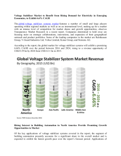
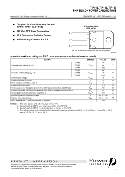
resistors
WK73S
higher power, wide terminal type flat
chip resistors
EU
NEW
features
• Wide-side termination (reverse-geometry)
type flat chip resistor
• High reliability and performance with T.C.R.
±100 x 10-6/K, resistance tolerance ±1%
• Marking: Black protective coat
• Products with lead-free terminations meet EU RoHS
requirements. EU RoHS regulation is not intended for
Pb-glass contained in electrode, resistor element and glass.
• AEC-Q200 Qualified
dimensions and construction
L
c
c
Type
L
(Inch Size Code)
W
Solder
Plating
Ni
Plating
t
Inner
Resistive Electrode
Film
d
Dimensions inches (mm)
W
c
d
2H2
(1020)
.098±.006 .197±.006 .016±.008
(2.5±0.15) (5.0±0.15) (0.4±0.2)
3A3
(1225)
.122±.006 .252±.006 .018±.008
(3.1±0.15) (6.3±0.15) (0.45±0.2)
t
.030±.006 .024±.004
(0.75±0.15) (0.6±0.1)
Protective
Coating Ceramic
Substrate
Derating Curve
100
% Rated Power
80
For resistors operated terminal temperature of described for each size or above,
a power rating shall be derated in accordance with the derating curve above.
Please refer to “Introduction of the derating curve based on the terminal part
temperature” in the beginning of our catalog before use.
If you want to use at rated power (*1), use derating curves based on the
terminal part temperature on the right side graph.
60
40
20
0
-60 -40 -20
-55
20 40 60 80
100 120
95
Terminal Part Temperature
(°C)
0
140
160
155
ordering information
New Part #
WK73S
2H2
Type
Size
WK73S
2H2: 2W
3A3: 3W
T
Termination
Material
T: Sn
TE
Packaging
TD: 7" 4mm pitch
punched paper
TE: 7" 4mm pitch
embossed plastic
For further information on
packaging, please refer
to Appendix A
33L0
F
Nominal
Resistance
±1%: 3 significant figures + 1
multiplier “R” indicates decimal
on value <100Ω
±5%: 2 significant figures + 1
multiplier “R” indicates decimal
on values <10Ω
All values less than 0.1Ω
(100mΩ) are expressed in mΩ
with “L” as decimal.
Ex: 33mΩ, 1% = 33L0
Resistance
Tolerance
F: ±1%
J: ±5%
Specifications given herein may be changed at any time without prior notice. Please confirm technical specifications before you order and/or use.
80
12/06/16
KOA Speer Electronics, Inc. • 199 Bolivar Drive • Bradford, PA 16701 • USA • 814-362-5536 • Fax: 814-362-8883 • www.koaspeer.com
higher power, wide terminal type flat
chip resistors
applications and ratings
Part
Designation
Power
Rating
Rated
Terminal
Part Temp.
WK73S2H2
2.0W1
95°C
3.0W1
WK73S3A3
T.C.R.
(X 10-6/K)
Resistance Range (Ω)
±100
±200
±800
±100
±200
±300
±800
95°C
F±1%
E-24/E-96
220m - 9.76
27m - 215m
—
360m - 9.76
33m - 357m
22m - 32.4m
—
J±5%
E-24
220m - 9.1
27m - 200m
10m - 24m
360m - 9.1
33m - 330m
22m - 30m
10m - 20m
Maximum
Working
Voltage
Maximum
Overload
Voltage
200V
400V
200V
Operating
Temp.
Range
-55°C
to
+155°C
400V
Rated voltage = √Power rating x resistance value or max. working voltage, whichever is lower
1
If you want to use at rated power use derating curves based on the terminal part temperature on the right side graph located on previous page.
If any questions arise whether to use the “Rated Ambient Temperature” or the “Rated Terminal Part Temperature”, please give priority to the
“Rated Terminal Part Temperature.” For more details refer to the “Introduction of the derating curves based on the terminal part temperature”
in the beginning of the catalog
environmental applications
Device Temperature Data
Terminal Part Temperature Rise (°C)
250
200
2H2-2W
3A3-3W
150
Room Temperature 25°C PCB: FR-4 t=1.6mm Cu foil
thickness=35µm
While using under high power, the temperature of the
product may increase depending on the condition of heat
dissipation from PCB.
Be sure to check the terminal part temperature as well as
precautions for use on delivery specifications before use.
100
50
0
0mm
10mm
20mm
30mm
40mm
50mm
Pattern Width (mm)
Performance Characteristics
Parameter
Resistance
T.C.R.
Overload (Short time)
Resistance to Solder Heat
Bending Test
Rapid Change of Temperature
Moisture Resistance
Endurance at 70°C
High Temperature
Exposure
Requirement ∆ R ±(%+0.005Ω)
Limit
Typical
Within specified
—
tolerance
Within specified
—
T.C.R.
±2%
±0.2%
±1%
±0.2%
±1%
±0.1%
±0.5%
±0.3%
±2%
±0.2%
±2%
±0.2%
±2%: J (±5%)
±1%: all others
±0.5%: J (±5%)
±0.2%: all others
Test Method
25°C
+25°C/-55°C and +25°C/+125°C
Rated voltage x 2.0 for 5 seconds
260°C ± 5°C, 10 seconds ± 1 second
Holding point 90mm, Bending 1 time, Bending 5mm
-55°C (30 minutes), +155°C (30 minutes), 5 cycles
40°C ± 2°C, 90%-95% RH, 1000 hours, 1.5 hr ON, 0.5 hr OFF cycle
70°C ± 2°C, 1000 hours, 1.5 hr ON, 0.5 hr OFF cycle
+155°C, 1000 hours
Additional environmental applications can also be found at www.koaspeer.com
Specifications given herein may be changed at any time without prior notice. Please confirm technical specifications before you order and/or use.
1/13/17
KOA Speer Electronics, Inc. • 199 Bolivar Drive • Bradford, PA 16701 • USA • 814-362-5536 • Fax: 814-362-8883 • www.koaspeer.com
81
resistors
WK73S
© Copyright 2026 Paperzz