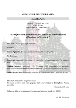
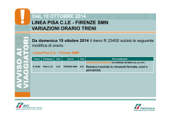
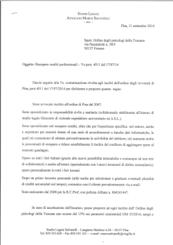
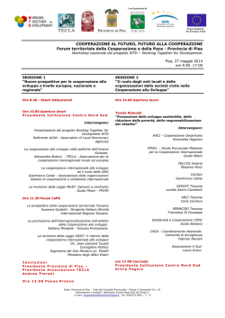
The International Archives of the Photogrammetry, Remote Sensing and Spatial Information Sciences, Volume XL-5/W3, 2013
The Role of Geomatics in Hydrogeological Risk, 27 – 28 February 2013, Padua, Italy
THE ELEVATION NET FOR THE SALTWATER INTRUSION PHENOMENON
ANALYSIS IN THE COASTAL PLAIN OF PISA
G. Caroti a, A. Piemonte a, M. Redini b
a
Laboratorio A.S.T.R.O., Dipartimento di Ingegneria Civile e Industriale, Università di Pisa, Largo Lucio Lazzarino 1
56123 PISA, tel 050 221 7770, fax 050 221 7779, e-mail [email protected]
b
Comune di Pisa, [email protected]
KEY WORDS: Surveying, Hydrology, Environment, DEM/DTM, LIDAR, Georeferencing, Model
ABSTRACT:
In coastal plains, such as that of Pisa, with particular reference to groundwater, the marine intrusion phenomenon occurs not only
through the freshwater/saltwater interface in the aquifer along the shore line, but also by the rise of the salt wedge in water courses,
in case they are in hydraulic connection with the aquifer itself. The depth of the interface is primarily regulated by the hydrostatic
freshwater/saltwater balance, that can be modified by anthropic exploitation of groundwater. To this day, seawater intrusion is
considered one of the most extensive and important processes that degrade water quality through an increase in salinity levels up to
values exceeding the standard for drinking water and irrigation systems, and endangering the future use of coastal waters. Given the
potential hazard of the phenomenon, control wells are set up in order to monitor its evolution, allowing to perform routine in-well
analyses aimed at measuring its characteristic parameters.
The essential foundation to reconstruct the freshwater/saltwater interface, and therefore also for the recognition of the phenomenon
of seawater intrusion, is represented by piezometric reconstructions integrated with hydrogeochemical information that can be
obtained directly from in-well measurements and indirectly through laboratory tests carried out on samples of water. A serious
limitation of the piezometric reconstructions is mostly represented by the margin of approximation with which the elevation of water
points has been established, which in turn result in uncertainty in the relationship between piezometric and hydrometric elevation.
This paper presents various methodologies, GNSS and conventional, to determine the elevation of piezometers , also evaluating the
accuracy obtainable and the requirements in terms of time, personnel and equipment.
1. INTRODUCTION
This work is part of a collaboration with the Municipality of
Pisa - Office of Regional Planning for the study of saltwater
intrusion on the Pisa coast.
In 2007, the City of Pisa has started the project "Implementation
of a network for measurement, control and monitoring in the
coastal plain of Pisa for the protection of water resources from
salt wedge intrusion and other degradation".
It's long been known that the salinity of Pisa coastal freshwater
is growing. Since 2007, the Municipality of Pisa is
reconstructing, through the relevant observations, the trend, in
both space and time, of the phenomenon, aiming at the
identification of effective actions to mitigate it, in accordance
with:
- the Regulation implementing Article 62 of the LR 03.01.05 n.
1 (Regulations for the government of the territory) in the field
of geological investigations;
- competences entrusted by Del. C. R. 30.01.90 n.47 (Directive
on coastal areas);
- L.R. 21.05.07 n. 29 and subsequent amendments (Hydraulic
emergencies).
There is an ongoing data collection activity aimed at:
- updating and detailed definition of the required knowledge
base;
- implementing the Directive on coastal areas (salt wedge
progression);
- updating
of
hydrogeological
vulnerability
maps
accompanying the “Piano Strutturale”;
- creating a detailed cognitive framework to be made available
to higher-level authorities and users
The objectives of this study are:
- the definition of salt wedge movements on the coast of Pisa in
response to hydrological stress and water management
practices in the surface aquifer;
- the definition of temporary safeguard measures;
- the definition of mitigation actions.
The study area extends from the mouth of Fiume Morto
Vecchio to the mouth of Calambrone, and coincides with the
boundaries of the Municipality overlooking the coast, for a total
of about 20 km, 12 of which related to the stint Marina di PisaCalambrone (Figure 1 ).
The area is subject to multiple hydrological stress linked to
incorrect practices of water resource management, which can be
summarized as follows:
- coastline recession;
- pumping;
- anthropogenic pressure (urban planning tools);
- riverbeds (suspended riverbeds);
- drainage system (minor networks, dewatering pumps).
Central to these primary objectives, is the need to
unambiguously and correctly georeference the different
databases coming from the various monitoring activities
implemented for the study of the phenomenon.
This contribution has been peer-reviewed.
doi:10.5194/isprsarchives-XL-5-W3-99-2013
99
The International Archives of the Photogrammetry, Remote Sensing and Spatial Information Sciences, Volume XL-5/W3, 2013
The Role of Geomatics in Hydrogeological Risk, 27 – 28 February 2013, Padua, Italy
3. GEOLOGICAL AND HYDROGEOLOGICAL
MODELS
The Municipality of Pisa, in the study for the protection of
water resources from salt wedge progression, has reconstructed
a geological model of the subsurface referring the height of
geognostic probing to an elevation model (DTM) derived from
laser scanner surveys, available for the entire study area.
Figure 1. Study area
In this context, starting Jun 2009, the authors’ contributions to
the project of the Municipality included:
- local check of the geoid model provided by the National
Military Geographical Institute (Istituto Geografico Militare –
IGM);
- measure of orthometric height in the vicinity of piezometric
wells;
- fixing of plano-altimetric position of network piezometers in
the area of monitoring, showing applicable survey methods,
taking into account not only the different levels of accuracy
but also the requirements as for time, personnel and
equipment resources.
2. THE PHENOMENON OF SALT WEDGE
In coastal plains, such as that of Pisa, with particular reference
to groundwater, the marine intrusion phenomenon occurs not
only in the aquifer along the shoreline through the freshwater /
saltwater interface, but also by the rise of the salt wedge in
water courses , in case these are in hydraulic connection with
the aquifer itself.
The depth of the interface is primarily regulated by hydrostatic
freshwater / saltwater balance, whose natural trend is modified
by anthropic exploitation of groundwater.
Seawater intrusion is currently seen as one of the most extensive
and important processes that degrade water quality, through an
increase in the salinity level up to values exceeding the standard
for drinking water and irrigation, also endangering future use of
coastal waters.
In order to monitor the evolution of this potentially harmful
phenomenon, control wells are set up to perform the routine
analysis aiming to measure characteristic parameters of
seawater intrusion.
The indispensable basis for reconstituting the freshwater /
saltwater interface trend, and therefore also for the recognition
of seawater intrusion phenomena, is represented by piezometric
reconstructions, integrated with hydrogeochemical information
obtained directly from in-well measurements and indirectly
through laboratory tests carried out on samples of water.
A major limitation of piezometric reconstruction is mostly
represented by the approximation with which the elevation of
water points has been determined, which in turn results in
problems of uncertainty in relating piezometric and hydrometric
elevation.
Figure 2. Geological model.
Based upon this subsurface geological model, a hydrogeological
model, greatly detailing just the coastal strip and a wide area
one, has been implemented.
The finite difference model ("visual modulo" software) set up
for the hydrogeological modeling has the following features:
- resolution of the model in the large triangular area bound to
the north by the Arno river, from the south to the east by the
Scolmatore-Navicelli channel and to the west from the sea:
120 m by 133 m cells;
- resolution of the model in the town of Marina di Pisa and
inland dunes: 68 m by 58 m cells;
- resolution of the model in the center of Tirrenia and inland
dunes: 72 m by 68 m cells.
The modeling results have provided high-quality, highreliability data.
By way of example, Figure 3 shows the basic scenario for the
area of Tirrenia, while Figure 4 shows the scenario with local
reduction of the charge for the area of Marina di Pisa.
Figure 3. Baseline scenario for the Tirrenia area (3D view
obtained by Modflow 3D Visual Explorer). Salinity distribution
(mg/l) at the end of the simulation period (2017)
This contribution has been peer-reviewed.
doi:10.5194/isprsarchives-XL-5-W3-99-2013
100
The International Archives of the Photogrammetry, Remote Sensing and Spatial Information Sciences, Volume XL-5/W3, 2013
The Role of Geomatics in Hydrogeological Risk, 27 – 28 February 2013, Padua, Italy
Figure 6. Location of surveyed wells
Figure 4. Scenario with local reduction of the charge for urban
areas in the Marina di Pisa area (3D view obtained by Modflow
3D Visual Explorer). Salinity distribution at -6m m a.s.l. (mg/l)
at the end of the simulation period (2017)
In order to compare the simulated information from the model
with the actual situation of each location and to continuously
collect hydrogeological information, 48 measurement points
have been selected to set up a hydrological monitoring network.
Since Italpos network station 0056 (Mada) is less than twelve
kilometers away from the area in question, mode "Nearest" was
chosen for consistency in the differential correction.
The accuracy degree of the survey was aligned with that
expected from the methodology used (Table 1).
Well
RMS01
RMS04
RMS16
RMS14
RMS18
RMS15
RMS29
RMS63
RMS17
RMS19
RTCM
Ref 0056
Latitude
43°40'44.44661"N
43°40'35.45364"N
43°40'05.15265"N
43°39'29.59786"N
43°39'21.08594"N
43°39'02.74095"N
43°39'06.57516"N
43°39'53.44377"N
43°40'06.09466"N
43°40'19.77974"N
Longitude
10°16'28.81194"E
10°16'25.01387"E
10°16'30.16503"E
10°16'58.69312"E
10°17'20.24294"E
10°17'06.23424"E
10°18'22.53573"E
10°18'29.78764"E
10°17'08.30390"E
10°17'34.35587"E
hell (m)
47.216
47.426
49.229
48.585
47.517
50.000
47.159
47.048
46.889
47.070
hell STD (m)
43°44'50.95870"N
10°21'57.83046"E
56.871
0.000
0.008
0.011
0.013
0.018
0.022
0.013
0.033
0.011
0.027
0.014
Table 1. Coordinates of wells by RTK.
To make the coordinates consistent with piezometric data, they
have been transformed into Gauss-Boaga and orthometric
height using *.gr2 IGM grids (Table 2).
Figure 5. Hydrological monitoring network
The use of data provided by fixed control points on the territory
as input for simulation models has required a previous check of
the elevation of the well heads over the entire monitoring
network and has led to a detailed analysis of different applicable
survey methods.
4. PLANO-ALTIMETRIC GEOREFERENCING OF
PIEZOMETRIC WELLS
The planimetric and altimetric coordinates of the 10 piezometric
wells located along the Pisa coast have been determined by
means of a real-time, phase differential GNSS survey.
In particular, a Leica GPS1200+ system, connected via GPRS
modem to the Italpos network server, has been used. The
selected differential correction was single station CMR
(Nearest) compared to the datum ETRS89 so that data were
consistent with the other databases used.
Well
RMS01
RMS04
RMS16
RMS14
RMS18
RMS15
RMS29
RMS63
RMS17
RMS19
North Roma40 (m)
4837027.970
4836749.218
4835816.156
4834729.083
4834473.956
4833903.120
4834048.092
4835496.619
4835858.398
4836289.668
East Roma40 (m)
1602773.644
1602692.857
1602822.565
1603478.415
1603965.185
1603660.154
1605367.575
1605507.237
1603676.245
1604253.105
Ha.s.l.(m)
0.745
0.944
2.712
2.024
0.946
3.404
0.568
0.518
0.374
0.572
Table 2. Cartographic coordinates Gauss-Boaga (North, East)
and elevation above mean sea level of well heads.
In two of the piezometric wells (RMS01 and RMS04) check
points were materialized at the side of the well head within the
same casing, while in the remaining cases the same spot used
for piezometric level measurements, on the edge of the PVC
pipe coating the well, has been used.
Transformation from ellipsoidal to orthometric heights, through
the undulation provided by *.gr2 IGM grids, has been tested in
the field, as shown in the next section.
This contribution has been peer-reviewed.
doi:10.5194/isprsarchives-XL-5-W3-99-2013
101
The International Archives of the Photogrammetry, Remote Sensing and Spatial Information Sciences, Volume XL-5/W3, 2013
The Role of Geomatics in Hydrogeological Risk, 27 – 28 February 2013, Padua, Italy
5. VERIFICATION OF ACCURACY OF GEOID
MODEL PROVIDED BY IGM IN THE MONITORING
AREA
The network of piezometric wells surveyed covers the area
between the mouth of the Arno River and the mouth of
Calambrone, for a total of about 12 km.
Figure 9. Static GPS survey network
Figure 7. Survey area
In this area, IGM leveling lines do not run along the coast, as
shown in Figure 8, and benchmark “104610”, placed near the
mouth of Arno along its left bank on the Lamone canal bridge,
has been torn, presumably due to road maintenance. The only
extant benchmark next to the monitoring area is that on the right
bank of Arno (0031#_D01_010 #), on the platform of the Italian
Navy Commandos base.
The network consists of 6 vertices, already included in the
IGM95 network or national elevation network, detailed as
follows:
1- 0031#_D01_010#, benchmark not connected to the IGM95
network. Platform of the Italian Navy Commandos base,
Bocca d'Arno – San Rossore;
2- 111901ass., IGM95 network benchmark. Piazza dei Fiori,
Tirrenia;
3- 111604, IGM95 network thickening point with benchmarkbased elevation. "Scalo Mortellini", SS1 km 327.100;
4- 104701, IGM95 network point with benchmark-based
elevation. "Cascine Nuove", San Rossore Park Area;
5- 111703, IGM95 network point with benchmark-based
elevation. Wall of the Arno drainage canal bank, Stagno;
6- 0028#_D02_001#, benchmark not connected to the IGM95
network. Piazzale Zara (harbor area), Livorno.
The survey was carried out with 6 dual-frequency GPS
receivers, used simultaneously on the network vertices.
The network has been compensated by imposing a constraint on
the vertex labeled "111901ass.", (Figure 10) and the results
have provided the ETRS89 coordinates of the vertices as
reported in Table 3.
Figure 8. Distribution of leveling lines along the Pisa coast
In order to verify the local accuracy of the IGM geoid model, a
triangular mesh GPS network, meeting the requirements of the
State-Regions Agreement for the thickening of the IGM95 base
network, has been established and measured.
Figure 10. GPS network adjustment
Network benchmarks
0031#_D01_010#
std (m)
111901ass*
std (m)
111604
std (m)
104701
This contribution has been peer-reviewed.
doi:10.5194/isprsarchives-XL-5-W3-99-2013
Latitude
Longitude
hell (m)
43°40'50.57456''N
0.003
10°16'50.25472''E
0.002
47.474
0.007
43°37'38.53770''N *
fixed
43°38'40.89172''N
0.003
43°41'36.17523''N
10°17'38.34670''E*
fixed
10°21'35.96315''E
0.002
10°20'26.16833''E
51.461*
fixed
51.014
0.006
50.628
102
The International Archives of the Photogrammetry, Remote Sensing and Spatial Information Sciences, Volume XL-5/W3, 2013
The Role of Geomatics in Hydrogeological Risk, 27 – 28 February 2013, Padua, Italy
std (m)
111703
std (m)
0028#_D02_001#
std (m)
0.003
43°35'57.90374''N
0.003
43°34'19.24400''N
0.003
0.003
10°21'10.69261''E
0.002
10°18'56.08950''E
0.002
0.007
50.899
0.006
49.100
0.007
Table 3. Coordinates of the vertices of the IGM network from
static survey
The transformation of the GPS network coordinates from
ETRF89 to Gauss-Boaga Roma40 and orthometric height,
performed with Verto software and *.gr2 grid referred to the
2005 geoid model (with an average deviation of ± 0.04 m with
respect to the high precision leveling lines) gave the results
shown in Table 4.
Network benchmarks
0031#_D01_010#
111901ass
111604
104701
111703
0028#_D02_001#
North Roma40 (m)
4837224.405
4831316.483
4833325.282
4838707.647
4828287.624
4825195.419
East Roma40 (m)
1603250.837
1604419.994
1609713.593
1608062.546
1609229.321
1606259.588
Ha.s.l.(m)
1.009
4.753
4.369
4.185
4.031
2.098
Table 4. ETRF89 to Gauss-Boaga transformation with *.gr2 grid
A first comparison in order to assess the accuracy achieved in
the survey, in both planimetry and elevation, was performed on
those vertices whose ETRF89 coordinates were reported on
monograph.
Table 5 shows that the differences in planimetric coordinates
are not significant and those in ellipsoidal height assume values
ranging from a minimum of about 2 cm, for point 104701, to a
maximum of about 7 cm, for point 111703: the precision
obtained in height falls therefore within the degree of accuracy
with which this type of survey returns elevation measures.
Network
benchmarks
111901ass*
111604
104701
111703
|Df|
|Dl|
Dhell (m)
0.00000"
0.00308"
0.00047"
0.00016"
0.00000"
0.00145"
0.00013"
0.00041"
0.000
-0.046
-0.019
0.069
Table 8 shows the undulation differences for each point, between
that assessed by benchmark derived elevations and that assessed
by grid-derived orthometric height (IGM 273.gr2 grid).
Network benchmarks
0031#_D01_010#
111604
104701
111703
0028#_D02_001#
DN (m)
0.010
0.012
-0.002
-0.064
-0.023
Table 8: Differences between the undulation derived from
benchmarks and from the IGM grid 273.gr2
From the results shown in Table 8 it can be seen as the
ITALGEO2005 model respects locally declared accuracy
(deviation values contained within ± 0.04 m) but for point
"111703" whose deviation is -0.064m.
Table 5 shows that this point has an equal amount shift on the
ellipsoidal elevation. This may suggest that this point has been
tampered with.
6. CONNECTION OF PIEZOMETRIC SURVEY
POINTS WITH THE ALTITUDE NATIONAL
NETWORK
The preceding paragraph pointed out the fact that in this area
IGM leveling lines do not run along the coast and the closest
benchmark to the monitoring area (benchmark "104610")
located along the Arno left bank has been completely altered.
The only extant benchmark in the immediate surroundings is
that on the right bank of the Arno (node 1 of the GPS network,
IGM name _D01_010 # 10031 #) on the platform of the Italian
Navy Commandos base.
The first necessity was to carry its elevation from the right bank
to the left bank of the river Arno.
Table 5. Comparison of ETRF89 coordinates of IGM points
from monographs vs. ETRF89 coordinates from static GPS
survey
The IGM-supplied geoid model provided has been locally
checked on those network points whose monograph reported the
elevation relative to a benchmark.
Table 6 shows the undulation of the geoid as assessed by
benchmark derived elevation, while in Table 7 the undulation
was assessed by determining the orthometric height from the
IGM 273.gr2 grid.
Network benchmarks
0031#_D01_010#
111604
104701
111703
0028#_D02_001#
hell (m)
47.474
51.014
50.628
50.899
49.100
Ha.s.l.(m)
0.999
4.357
4.187
4.095
2.121
N (m)
46.475
46.657
46.441
46.804
46.979
Figure 11. Connection of the wells to the national leveling
network
In order to establish an altimetric connection between the two
banks (about 130m away) a reciprocal geometric leveling was
performed between IGM benchmark “10031#_D01_010#” and
benchmark "sezione 9" established by the Hydrographic and
Tidal Office of the Municipality of Pisa on the left bank (with
orthometric height derived from GPS survey).
Table 6: Geoid undulation assessed by benchmark derived
elevations
Network benchmarks
0031#_D01_010#
111901ass
111604
104701
111703
0028#_D02_001#
hell (m)
47.474
51.461
51.014
50.628
50.899
49.100
Ha.s.l.(m)
1.009
4.753
4.369
4.185
4.031
2.098
N (m)
46.465
46.708
46.645
46.443
46.868
47.002
Table 7: Geoid undulation assessed by grid-derived orthometric
height (IGM 273.gr2 grid)
This contribution has been peer-reviewed.
doi:10.5194/isprsarchives-XL-5-W3-99-2013
103
The International Archives of the Photogrammetry, Remote Sensing and Spatial Information Sciences, Volume XL-5/W3, 2013
The Role of Geomatics in Hydrogeological Risk, 27 – 28 February 2013, Padua, Italy
Figure 12. Altimetric connection by reciprocal leveling between
two benchmarks placed on opposite sides of the Arno river
For this purpose, a Wild NA2 level with a Wild GPM3 parallel
plate micrometer, and two Wild GPLE2 double graduation invar
leveling rods, have been used.
The orthometric height of benchmark of the Hydrographic and
Tidal Office of the Municipality of Pisa was equal to:
H"sezione 9" = 0.79031 +/- 0.00019m
This benchmark originated a leveling line connecting the
benchmarks established for the elevation reference of the well
heads.
It was therefore decided to test the accuracy with which the
elevation of the well heads can be extrapolated directly from the
DTM.
The elevation values at the planimetric coordinates detected by
RTK GPS were obtained by bilinear interpolation from the
DTM. Those values were, therefore, corrected to take account
of the fact that the point surveyed by GPS, coinciding with the
reference point of the piezometric measurements, is located
within a manhole lowered by a few tens of centimeters with
respect to the pavement or road surface.
The comparison of elevation values interpolated from DTM
with those obtained by the transformation of ellipsoidal height
via the IGM 273.gr2, yields deviations in the order of a few
centimeters (Table 10).
Orthometric
Interpolated Wellhead
Interpolated
heights
heights heights Ellipsoid
heights
calculated
from
ground H-Hi-dH H-Hc-dH
Well heights
from inland
by IGM's
coastal
level
(m)
(m)
h (m)
DTM
grid *.gr2
DTM
heights
Hi (m)
H (m)
Hc (m)
dH (m)
RMS01 47.216
0.745
1.011
-0.25
-0.016
RMS04 47.426
0.944
1.054
-0.16
0.050
RMS16 49.229
2.712
2.955
-0.27
0.027
RMS14 48.585
2.024
2.156
-0.29
0.158
RMS18 47.517
0.946
1.306
1.156
-0.28
-0.080
0.070
RMS15 50.000
3.404
3.808
3.794
-0.36
-0.044
-0.030
RMS29 47.159
0.568
0.995
-0.29
-0.137
RMS63 47.048
0.518
0.843
-0.26
-0.065
RMS17 46.889
0.374
0.913
0.880
-0.28
-0.264
-0.231
RMS19 47.070
0.572
0.791
0.781
-0.19
-0.029
-0.019
Table 10. Orthometric elevations derived from DTM and
comparison with those derived from RTK GPS
8. CONCLUSIONS
Figure 13. Leveling line between benchmark "sezione 9" and
piezometric wells
Table 9 shows the leveling elevation of two wells and their
differences compared to orthometric height by RTK survey.
Well
RMS01
RMS04
Ha.s.l.(m) from lev. (m)
0,82628
1,02128
Ha.s.l.from RTK (m)
0.745
0.944
D Ha.s.l. (m)
0,08128
0,07728
Table 9. Orthometric heights from leveling of two wells and
comparison with those determined by RTK
7. ALTIMETRIC GEOREFERENCING THROUGH
DENSE DTM
For the area of the Pisa coast affected by the phenomenon of the
salt wedge a dense digital elevation model, with accuracy
<10cm, is available.
This elevation model has been used as a basis for
hydrogeological modeling as described in section 3.
This is based on a simplified mesh elevation model, resampled
with cell size of about one hundred meters.
It is apparent that this simplification leads to use an average
value of altitude data for the individual cells.
The interest in this study was to verify and compare the
different methods by means of which hydrological monitoring
points, established for the study of the phenomenon of the salt
wedge on the Pisa coast, can be altimetrically framed.
This study has resulted in the creation of hydrogeological
models for which the definition of the orthometric height of soil
and groundwater is paramount. Firstly, these points have been
detected by phase interference GPS survey and the local
transformation from ellipsoidal to orthometric height via IGM
*.gr2 grids has been positively validated.
The availability of a high precision and dense digital model has
shown that the height of the same spots can be extrapolated by
the elevation model with accuracies of a few centimeters.
To complete the survey on the different methodologies for
altimetric framing, the network of piezometric monitoring
points was also connected to a high-precision national leveling
benchmark, with the leveling lines measured with classical
methodology. This survey has of course produced very highprecision data, commensurate with the requirements in both
time and resources inherent with the methodology in itself.
Provided this picture of precision obtainable in altimetric
framing, firms and offices involved in hydraulic modeling have
been allowed to decide which method to adopt based on
financial and time resources.
9. REFERENCES
Ambrosio, M., Curcio, C., Fagioli, M., Giannecchini, R., 2011.
L’acquifero freatico costiero della Pianura di Pisa tra Fiume
Arno e Canale Scolmatore: implementazione e calibrazione del
modello numerico. In Geologia Tecnica e Ambientale, ISBN
1722-0025.
This contribution has been peer-reviewed.
doi:10.5194/isprsarchives-XL-5-W3-99-2013
104
The International Archives of the Photogrammetry, Remote Sensing and Spatial Information Sciences, Volume XL-5/W3, 2013
The Role of Geomatics in Hydrogeological Risk, 27 – 28 February 2013, Padua, Italy
Bitelli, G., Roncari, G., Tini, M. A., Vittuari, L., 2011.
Metodologia per la determinazione con alta precisione del
dislivello esistente tra due punti nell’attraversamento di zone
impraticabili. In Atti 15aConferenza Nazionale ASITA. Pp. 363371.
Butteri, M., Doveri, M., Giannecchini, R., Gattai P., 2010.
Hydrogeologic-hydrogeochemical multidisciplinary study of the
gravel confined aquifer in the coastal Pisan Plain (Tuscany)
between the Arno River and Scolmatore Canal (Tuscany). In
Memorie Descrittive della Carta Geologica d’Italia, Vol. 90,
51-66.
Caroti, G., Piemonte, A., 2011. Analisi dei dati altimetrici
disponibili per il territorio comunale di Pisa. In Geomatica le
radici del futuro, Edizioni SIFET, ISBN 88-901939-6-4, pp.
157-161.
NOAA Sentinel Site Program, 2011. “Accurate Elevations for
Sea Level Change Sentinel Sites”.
ftp://www.ngs.noaa.gov/dist/phensel/Reviews/Matt_Kimball/A
_E_f_S_L_R_S_S_092911_MEK_Comments.pdf
This contribution has been peer-reviewed.
doi:10.5194/isprsarchives-XL-5-W3-99-2013
105
© Copyright 2026 Paperzz