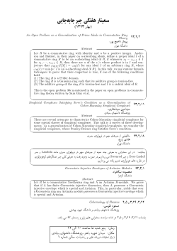
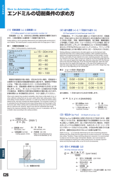
ALVAN ® EXPANDING REAMERS WITH CUTTING RING “COMPOSIT” MODULAR SYSTEM Modular Composit shank — LONG SERIES Brazed carbide (from diam. 17,60 to 60,59 mm) through holes with Series 4300 - radial through tool coolant A B blind holes with Series 4305 - radial through tool coolant A 35 B 35 ØD mm series 4305 A mm 17,60 - 21,59 1 12 21,60 - 25,59 25,60 - 32,59 32,60 - 40,59 1 1 1 40,60 - 45,59 45,60 - 60,59 1 1,5 ØM ØD ØM C Ød ØD C Expanding reamers with adjustment in front of the cutting ring series 4300 Ød A mm mm B mm C mm 11 121 11 50 6 12 15,6 22 11 11 14 121 153 179 12 14 16 50 50 50 6 6 6 25,4 30 15 20,5 201 214 16 18,5 50 50 6 6 Mod. shank Number ØM of teeth SPARE PARTS Series 4300 4 1 Series 4305 2 5 1 2 3 3 series 4300 ØD mm Complete mandrel without cutting ring series 4300 4305 series 4305 Conical ring Ring nut or nut 1 4 Complete mandrel without cutting ring key Conical ring 5 1 Conical ring Conical ring second third expansion expansion Drive pin 2000 - CO 3 17,60 - 21,59 4300-MC-010 2010-AC-010 2000-DA-010 4305-MC-010 4001-CH-015 4001-AC-115 4001-AC-215 - 010 010 21,60 - 25,59 4300-MC-020 2010-AC-010 2000-DA-010 4305-MC-020 4001-CH-015 4001-AC-115 4001-AC-215 - 020 020 25,60 - 29,59 4300-MC-030 2010-AC-020 2000-DA-020 4305-MC-030 4001-CH-025 4001-AC-125 4001-AC-225 4001-AC-325 030 030 29,60 - 32,59 4300-MC-030 2010-AC-020 2000-DA-020 4305-MC-035 4001-CH-025 4001-AC-125 4001-AC-225 4001-AC-325 030 040 32,60 - 36,59 4300-MC-040 2010-AC-030 2000-DA-060 4305-MC-040 4001-CH-035 4001-AC-135 4001-AC-235 4001-AC-335 040 040 36,60 - 40,59 4300-MC-040 2010-AC-030 2000-DA-060 4305-MC-045 4001-CH-035 4001-AC-135 4001-AC-235 4001-AC-335 040 050 40,60 - 45,59 4300-MC-050 2010-AC-040 2000-DA-090 4305-MC-050 4001-CH-045 4001-AC-145 4001-AC-245 4001-AC-345 060 060 45,60 - 49,59 4300-MC-060 2010-AC-050 2000-GH-880 4305-MC-060 4001-CH-055 4001-AC-155 4001-AC-255 4001-AC-355 060 060 49,60 - 55,59 4300-MC-070 2010-AC-050 2000-GH-880 4305-MC-070 4001-CH-055 4001-AC-155 4001-AC-255 4001-AC-355 070 070 55,60 - 60,59 4300-MC-070 2010-AC-050 2000-GH-880 4305-MC-075 4001-CH-055 4001-AC-155 4001-AC-255 4001-AC-355 070 080 2 Cutting ring 58 TECHNICAL INFORMATION AND CUTTING PARAMETERS STANDARD SPEED REAMING ALVAN ® Hard metal brazed carbide (our ref. H.M.) MATERIAL TO WORK Mild Steel 2 Reamer Ø mm STOCK ALLOWANCE Ø mm Up to 600 Up to 10 10 - 22 22 - 40 40 - 50 50 - 70 70 - 100 0,10 - 0,20 0,15 - 0,25 0,20 - 0,40 0,30 - 0,40 0,35 - 0,50 0,40 - 0,50 Greater than 600 Up to 10 10 - 22 22 - 40 40 - 50 50 - 70 70 - 100 0,10 - 0,20 0,15 - 0,25 0,20 - 0,30 0,30 - 0,40 0,35 - 0,50 0,40 - 0,50 400 - 1000 Up to 10 10 - 22 22 - 40 40 - 50 50 - 70 70 - 100 0,10 - 0,20 0,15 - 0,25 0,20 - 0,30 0,30 - 0,40 0,35 - 0,50 0,40 - 0,50 800 - 1500 Up to 10 10 - 22 22 - 40 40 - 50 50 - 70 70 - 100 0,10 - 0,20 0,15 - 0,25 0,20 - 0,30 0,30 - 0,40 0,35 - 0,50 0,40 - 0,50 Up to 10 10 - 22 22 - 40 40 - 50 50 - 70 70 - 100 0,10 - 0,20 0,15 - 0,30 0,30 - 0,40 0,30 - 0,40 0,35 - 0,50 0,40 - 0,50 300 - 700 Up to 10 10 - 22 22 - 40 40 - 50 50 - 70 70 - 100 0,10 - 0,20 0,15 - 0,25 0,20 - 0,30 0,30 - 0,40 0,35 - 0,50 0,40 - 0,50 Up to 500 Up to 10 10 - 22 22 - 40 40 - 50 50 - 70 70 - 100 0,10 - 0,25 0,15 - 0,25 0,25 - 0,40 0,30 - 0,40 0,35 - 0,50 0,40 - 0,50 Up to 600 Up to 10 10 - 22 22 - 40 40 - 50 50 - 70 70 - 100 0,10 - 0,25 0,15 - 0,25 0,25 - 0,40 0,30 - 0,40 0,35 - 0,50 0,40 - 0,50 Up to 500 Up to 10 10 - 22 22 - 40 40 - 50 50 - 70 70 - 100 0,10 - 0,2 0,15 - 0,3 0,20 - 0,4 0,30 - 0,4 0,35 - 0,5 0,40 - 0,5 Up to 10 10 - 22 22 - 40 40 - 50 50 - 70 70 - 100 0,10 - 0,20 0,15 - 0,25 0,20 - 0,30 0,30 - 0,40 0,35 - 0,50 0,40 - 0,50 Up to 10 10 - 22 22 - 40 40 - 50 50 - 70 70 - 100 0,10 - 0,20 0,15 - 0,25 0,20 - 0,30 0,30 - 0,40 0,35 - 0,50 0,40 - 0,50 N / mm Unalloyed Low alloyed Structural steel Fused Metal Alloy steel Stainless steel Strongly alloy steel Steel with manganese Grey cast iron Spheroidal cast iron (pearlitic) Malleable cast iron Spheroidal cast iron (ferritic) Copper and alloys Up to 200HB Greater than 200 HB Brass Bronze Bronze phosphorous Alluminium and light alloys Titanium and alloys Syntetic materials 6 SURFACE SPEED m / min FEED mm / rev 7 - 15 0,15 - 0,30 0,25 - 0,50 0,30 - 0,80 0,60 - 1,00 0,60 - 1,20 0,80 - 1,50 6 - 10 0,10 - 0,30 0,20 - 0,40 0,30 - 0,60 0,40 - 0,80 0,50 - 0,90 0,60 - 1,20 4-8 0,10 - 0,30 0,20 - 0,40 0,30 - 0,60 0,40 - 0,80 0,50 - 0,90 0,60 - 1,20 3-6 0,10 - 0,20 0,15 - 0,40 0,30 - 0,50 0,30 - 0,70 0,40 - 0,80 0,50 - 1,00 ≤ 200 HB 15 - 30 > 200 HB 10 - 20 0,20 - 0,50 0,40 - 0,60 0,60 - 1,20 0,75 - 1,50 0,80 - 1,60 1,00 - 1,80 8 - 12 0,15 - 0,30 0,40 - 0,60 0,50 - 1,00 0,75 - 1,50 0,80 - 1,60 1,00 - 1,80 10 - 18 0,15 - 0,40 0,20 - 0,60 0,25 - 0,90 0,40 - 1,10 0,50 - 1,20 0,60 - 1,50 10 - 20 0,15 - 0,40 0,25 - 0,60 0,50 - 0,80 0,60 - 1,00 0,70 - 1,10 0,80 - 1,20 15 - 30 0,20 - 0,40 0,30 - 0,60 0,40 - 1,00 0,75 - 1,50 0,80 - 1,60 0,90 - 1,80 5-8 0,15 - 0,30 0,20 - 0,40 0,30 - 0,50 0,40 - 0,60 0,60 - 0,80 0,80 - 1,20 15 - 30 0,20 - 0,50 0,40 - 0,80 0,50 - 1,40 0,80 - 1,50 0,90 - 1,60 1,00 - 1,80 LUBRICANT Emulsible oil Cutting oil Emulsible oil Cutting oil Emulsible oil Cutting oil Emulsible oil Cutting oil Oil Emulsible oil Cutting oil Emulsible oil Cutting oil Emulsible oil Emulsible oil Cutting oil Emulsible oil Oil Cutting oil Emulsible oil Cutting oil Compressed air Dry Emulsible oil ALVAN TECHNICAL INFORMATION AND CUTTING PARAMETERS HIGH SPEED & HIGH FEED REAMING ® Hard metal brazed carbide coated TiN - TiCN - TiAIN (our ref. TIN - TIC - TIA) Cermet brazed carbide (our ref. AVC) *AVC reamers are available coated TiN, TiCN or TiAlN MATERIAL TO WORK Mild Steel 2 Reamer Ø mm STOCK ALLOWANCE Ø mm Up to 600 up to 10 10 - 18 18 - 40 40 - 80 over 80 0,08 - 0,15 0,15 - 0,25 0,15 - 0,30 0,20 - 0,40 0,25 - 0,50 Greater than 600 up to 10 10 - 18 18 - 40 40 - 80 over 80 0,08 - 0,15 0,15 - 0,25 0,15 - 0,30 0,20 - 0,40 0,25 - 0,50 up to 10 10 - 18 18 - 40 40 - 80 over 80 up to 10 10 - 18 18 - 40 40 - 80 over 80 0,08 - 0,15 0,15 - 0,25 0,15 - 0,30 0,20 - 0,40 0,25 - 0,50 0,08 - 0,15 0,15 - 0,25 0,15 - 0,30 0,20 - 0,40 0,25 - 0,50 up to 10 10 - 18 18 - 40 40 - 80 over 80 0,08 - 0,15 0,15 - 0,25 0,15 - 0,30 0,20 - 0,40 0,25 - 0,50 300 - 700 up to 10 10 - 18 18 - 40 40 - 80 over 80 0,08 - 0,15 0,15 - 0,25 0,15 - 0,30 0,20 - 0,40 0,25 - 0,50 Up to 500 up to 10 10 - 18 18 - 40 40 - 80 over 80 0,08 - 0,15 0,15 - 0,25 0,15 - 0,30 0,20 - 0,40 0,25 - 0,50 Up to 600 up to 10 10 - 18 18 - 40 40 - 80 over 80 0,08 - 0,15 0,15 - 0,25 0,15 - 0,30 0,20 - 0,40 0,25 - 0,50 Up to 500 up to 10 10 - 18 18 - 40 40 - 80 over 80 0,08 - 0,15 0,15 - 0,25 0,15 - 0,30 0,20 - 0,40 0,25 - 0,50 up to 10 10 - 18 18 - 40 40 - 80 over 80 0,10 - 0,20 0,15 - 0,25 0,20 - 0,40 0,30 - 0,40 0,30 - 0,50 N / mm Unalloyed Low alloyed Structural steel Fused Metal Alloy steel 400 - 1000 Stainless steel Strongly alloy steel Steel with manganese 800 - 1500 Grey cast iron Up to 200HB Spheroidal cast iron (pearlitic) Malleable cast iron Greater than 200 HB Spheroidal cast iron (ferritic) Copper and alloys Brass Bronze Bronze phosphorous Alluminium and light alloys Titanium and alloys H.M. coated TiN - TiCN TiAIN CERMET AVC * Lead-in A,G Lead-in E, N, M SURFACE SPEED m / min SURFACE SPEED m / min FEED mm / rev FEED mm / rev 90 - 300 0,20 - 0,40 0,40 - 0,60 0,50 - 0,80 0,50 - 1,00 0,80 - 1,50 0,30 - 0,60 0,40 - 1,00 0,60 - 1,20 0,80 - 1,60 1,00 - 2,20 80 - 200 0,20 - 0,40 0,30 - 0,60 0,40 - 0,70 0,50 - 0,80 0,80 - 1,20 0,30 - 0,50 0,30 - 0,80 0,40 - 1,00 0,60 - 1,40 1,00 - 2,00 0,20 - 0,40 0,30 - 0,60 0,40 - 0,70 0,50 - 0,80 0,80 - 1,20 0,15 - 0,30 0,20 - 0,50 0,30 - 0,60 0,40 - 0,80 0,60 - 1,00 0,30 - 0,50 0,30 - 0,80 0,40 - 1,00 0,60 - 1,40 1,00 - 2,00 0,20 - 0,40 0,30 - 0,60 0,40 - 0,80 0,50 - 1,00 0,70 - 1,40 50 - 70 0,20 - 0,40 0,35 - 0,60 0,40 - 1,00 0,60 - 1,30 0,80 - 1,70 0,30 - 0,60 0,50 - 0,80 0,60 - 1,50 0,80 - 1,60 1,00 - 2,25 30 - 50 0,20 - 0,40 0,35 - 0,60 0,40 - 1,00 0,60 - 1,30 0,80 - 1,70 0,30 - 0,60 0,50 - 0,80 0,60 - 1,50 0,80 - 1,60 1,00 - 2,25 60 - 80 40 - 70 30 - 50 60 - 150 15 - 30 60 - 120 60 - 120 100 - 200 0,20 - 0,40 0,40 - 0,70 0,50 - 0,80 0,60 - 1,00 0,80 - 1,40 80 - 160 0,15 - 0,30 0,20 - 0,40 0,30 - 0,60 0,40 - 0,80 0,60 - 1,00 100 - 300 100 - 200 0,20 - 0,40 0,40 - 0,70 0,50 - 0,80 0,60 - 1,00 0,80 - 1,40 20-60 0,15 - 0,30 0,20 - 0,40 0,30 - 0,50 0,40 - 0,60 0,50 - 0,70 HIGH SPEED FOR ALUMINIUM REAMING Aluminium with silicon greater than 10% - brazed carbide with PKD PKD hard metal - Surface speed up to 1500 m/min. - When using PKD reamers a machine tool with high rigidity and absolute precision is a minimum requirement. - Each application must be assessed by our technical department. 7 ALVAN EXPANDING REAMERS CUTTING GEOMETRY Cutting ring Integral expanding reamer 45° 45° Single lead-in Code G 8° Double lead-in Code A 75° 30° Titanium lead-in Code T "F" lead-in to reduce the feed of 40% compared with the values on pages 6-7 ® "L" lead-in to reduce the feed of 40% compared with the values on pages 6-7 Frontal lead-in Code L 90° 20° Frontal lead-in Code F Negative lead-in Code N 9 "N" lead-in ideal for through hole. It is possible to increase the feed up to 100% of the values indicated on pages 6-7 EXPANDING REAMERS CUTTING GEOMETRY ALVAN ® Approach angles MATERIAL TO WORK TENSILE STRENGTH APPROACH ANGLE* Iron and mild steel (C < 0,2%) 50 Kg / mm 2 G-A-E Mild steel (C 0,2 < 0,3%) 60 Kg / mm 2 N-A-E Mild steel (C 0,3 < 0,4%) 70 Kg / mm 2 N-A-E Mild steel (C 0,4 < 0,5%) 80 Kg / mm 2 N-A-E Alloy steel ≤ 80 Kg / mm 2 G-N-A-E Alloy steel 90 Kg / mm 2 G-N-E Alloy steel 100 Kg / mm 2 G-N-M Alloy steel > 100 Kg / mm 2 G-N-M from 50 Kg / mm 2 to 90 Kg / mm 2 G-N-M from 150 HB to 320 HB G-N-E Stainless and refractory steel Grey, spheroidal and malleable cast iron Titanium and titanium alloy Tempered steel T-E 48 - 64 HRc G-N-M Pure copper G-N-E Electrolytic copper G-N-E Brass / Bronze G-N-E Alluminium alloy < 10% Si G-A-E Alluminium alloy > 11% Si G-E Magnesium alloy G-A-E Thermoplastic material G-E Thermosetting resins G-E Stiffened synthetic material G-E * Do not use negative lead-in on blind holes Negative lead-in "N" can be used on large range of materials: please apply to our technical department. Usually ex-stock: - single lead-in G 11 ALVAN EXPANDING REAMERS WITH CUTTING RING ® Expanding reamers without coolant Expanding reamers with central through tool coolant (ideal application for blind holes) Expanding reamers with radial through tool coolant (ideal application for through holes) Expanding reamers with central and radial through tool coolant ØD ØD Recommended values for lubricants Pressure (Bar) Capacity (L/Min.) 20 200 18 180 16 160 14 140 12 120 10 100 8 80 6 60 4 40 2 20 0 0 10 30 50 70 90 120 Ø REAMER (mm) It is important to use a good quality lubricant. The cutting rings can be expanded for recovering the starting diameter. 34 ALVAN CUTTING RINGS from diameter 17,60 to 200,59 mm C ØD ØD mm C mm Number of teeth 17,60 - 21,59 11 6 21,60 - 25,59 12 6 25,60 - 32,59 14 6 32,60 - 45,59 16 6 45,60 - 79,59 18,5 6 79,60 - 100,59 18,5 8 100,60 - 110,59 18,5 10 110,60 - 200,59 18,5 12 The ALVAN® cutting rings are modular and compatible with all the reamers indicated on page 36 to 58. We guarantee a regrinding and re-brazing rapid service of the damaged cutting edges (consult our technical department). The cutting edges are in an asymmetric way to assure the best roundness of the hole (see page 74). Holes with restricted tolerances (ISO 5 and 6) can be supplied and the expansion assures a perfect holding of the reaming diameter. Lead-in: cutting rings with G lead-in are usually available from stock (see page 11-12-13). Diameters and tolerances: cutting rings of integer metric diameters with H7 tolerances are usually available from stock. The ALVAN® cutting rings are manufactured to the middle of the hole tolerance so they must be assembled and adjusted to the same diameter. It is important to comply with this direction in order to have a good working and life of the tool. LEFT HAND HELICAL FLUTES CUTTING RINGS from diameter 32,60 to 200,59 mm. ON REQUEST. 35 ® ALVAN ® EXPANDING & FIXED REAMERS INSTRUCTIONS 1) Diameter measurement The diameter of the reamers and of the cutting rings is measured with a micrometer. We recommend the use of a comparator style micrometer with at least a 2µm resolution to avoid micro chipping of the cutting edges. To allow setting of the reamer, two cutting edges are exactly 180° opposed. These are marked with a coloured dimple (see diagram below). Measurement must be taken from the front of the cutting edges only. The red dimple indicates that the tool has been ground with a single lead-in angle (code G), the blue dimple indicates a double lead-in angle (code A). Dimple Dimple Diameter Diameter 2) Tolerance All the reamers are ground to the requested diameter and set to nominal tolerance for expanding reamers and 3/4 of minimum tolerance for fixed reamers. 3) Expanding reamers adjustment The adjustment must be made to compensate for wear to the cutting edges when the size reaches its lower tolerance. This operation can be repeated several times until the surface finish of the hole deteriorates to an unacceptable level, then the reamer must be reground. The maximum expansion is about 1% of the diameter for the integral reamers and about 4% of the diameter for the cutting rings. 74 EXPANDING REAMERS INSTRUCTIONS ALVAN ® Assembly - Adjustment - Disassemby EXPANDING REAMERS WITH CUTTING RING with assembly and adjustment in the front Series 2000-2010-2050 from diam. 17,60 to 100,59 mm Series 4550-4500-4330 from diam. 17,60 to 100,59 mm Series 4200-4250-4350 from diam. 17,60 to 200,59 mm Series 4300 from diam. 17,60 to 60,59 mm 5 1 2 4 3 1) Assembly Insert the cutting ring (item 2) on the mandrel (item 4) with the drive pins (item 3) assembled. Insert the conical ring (item 1). Screw the nut (item 5) and lock it manually: the thread is left handed. We recommend lubricating the thread and the conical surface of contact between the cutting ring and the conical ring with antifriction Molycote grease. 2) Adjustment procedure Turn the nut slowly, checking the diameter setting of the cutting ring with a micrometer, paying attention that the drive pins are in traction in the opposite direction to the cutting action of the reamer. When the required diameter is achieved, the tool is ready for use. 3) Disassembly Unscrew the nut. Remove the components from the mandrel. 76 ALVAN EXPANDING REAMERS INSTRUCTIONS ® Assembly - Adjustment - Disassemby EXPANDING REAMERS WITH CUTTING RING with assembly and adjustment on the rear Series 2500 - 2505 - 2530 - 2535 - 2550 - 2555 from diam. 17,60 to 45,59 mm 3 1 2 6 5 4 1) Assembly Screw the nut (item 5) on the mandrel (item 4): the thread is right handed. Insert the bush (item 6) on the mandrel. Mount the cutting ring (item 2) onto the conical screw (item 1) and over the drive pins (item 3). Tighten the conical screw onto the mandrel , taking care that the contact surfaces are very clean. Look the screw to the torque setting stated in table1. We recommend lubricating the thread and the conical surface of contact between the cutting ring and the conical ring with antifriction Molycote grease. 2) Adjustment procedure Turn the nut slowly, checking the diameter setting of the cutting ring with a micrometer, paying attention that the drive pins are in tranction, in the opposite direction to the cutting action of the reamer. When the required diameter is achived, the tool is ready for use. 3) Disassembly Loosen the nut and remove the screw. Remove the components from the mandrel. Use a dynamometric key to avoid breaking the conical screw Diameter mm Torque settings Kgm 18 - 25 26 - 32 33 - 40 41 - 45 1,4 - 1,6 2,2 - 2,5 3,6 - 4 4,6 - 5 77 table 1 EXPANDING REAMERS INSTRUCTIONS ALVAN ® Assembly - Adjustment - Disassemby EXPANDING REAMERS WITH CUTTING RING with assembly and adjustment on the rear Series 2500 - 2505 - 2530 - 2535 - 2550 - 2555 from diam. 45,60 to 100,59 mm 3 4 2 6 5 1) Assembly Mount the cutting ring (item 2) and the bush (item 6) onto the mandrel (item 4). Screw the ring nut (item 5) onto the mandrel and lock it manually: the thread is right handed. We recommend lubricating the thread and the conical surface of contact between the cutting ring and the mandrel with antifriction Molycote grease. 2) Adjustment procedure Turn the ring nut slowly, checking the diameter setting of the cutting ring with a micrometer, paying attention that the drive pins (item 3) are in traction in the opposite direction to the cutting action of the reamer. When the required diameter is achieved, the tool is ready for use. 3) Disassembly Unscrew the ring nut. Remove the components from the mandrel. 78 ALVAN EXPANDING REAMERS INSTRUCTIONS ® Assembly - Adjustment - Disassemby EXPANDING REAMERS WITH CUTTING RING with assembly and adjustment in the front Series 4000 - 4050 from diam. 79,60 to 200,59 mm Series 4100 - 4150 from diam. 79,60 to 200,59 mm 6 1 2 4 5 3 1) Assembly With the drive pins (item 3) assembled, mount the flange (item 4) onto the mandrel (item 5). Assemble the cutting ring (item 2) so that the slot on the left side of the dimple is mounted onto the drive pins. Insert the conical ring (item 1). Screw the ring nut (item 6) onto the mandrel and tighten manually, so that the conical ring makes contact with the cutting ring: the thread is left handed. We recommend lubricating the thread and the conical surface of contact between the cutting ring and the conical ring with antifriction Molycote grease. 2) Adjustment procedure Turn the ring nut slowly (using a pin spanner) checking the diameter setting of the cutting ring with a micrometer, paying attention that the drive pins are in traction, in the opposite direction to the cutting action of reamer. When the required diameter is achieved, the tool is ready for use. 3) Disassembly Unscrew the ring nut. Remove the components from the mandrel. 79 EXPANDING REAMERS INSTRUCTIONS ALVAN ® Assembly - Adjustment - Disassemby EXPANDING REAMERS WITH CUTTING RING with assembly and adjustment in the front Series 2015 from diam. 17,60 to 100,59 mm Series 4000 - 4050 from diam. 17,60 to 79,59 mm Series 4355-4505-4555 from diam. 17,60 to 100,59 mm Series 4305 from diam. 17,60 to 60,59 mm 5 1 2 4 3 1) Assembly Mount the cutting ring (item 2) onto the mandrel (item 4) with the drive pins (item 3) assembled. Screw the conical ring nut onto the mandrel and lock it manually: the thread is left handed. Lubricate the thread and the conical surface of contact between the cutting ring and the conical ring with antifriction Molycote grease. 2) Adjustment procedure Turn the conical ring nut slowly using a pin spanner (item 5) supplied with reamers from diameter 17,60 to 40,59 mm, checking the diameter setting of the cutting ring with a micrometer. When the required diameter is achieved unscrew the conical ring until there is a click and the drive pins are in traction in the opposite direction to the cutting action of the reamer. The reamer is ready for use. 3) Disassembly Unscrew the conical ring nut. Remove the components from the mandrel. 80 ALVAN BASIC SHANKS DIN 69871/1 B + A ® [1] MODULAR REDUCER D L 40 50 02B.40.63.50 40 02B.40.80.50 40 02B.45.50.27 02B.45.63.27 ORDER CODE ISO 02B.40.50.27 STANDARD EQUIPMENT ACCESSORIES screw ring nut plugs modular screw key modular ring nut key 27 TAB2808 TAB2809 M5x5TG hexagon 10 ATR8851 63 50 TAB9038 TAB2793 M5x5TG hexagon 12 ATR8851 80 50 TAB9038 TAB2793 M5x5TG hexagon 12 ATR8851 45 50 27 TAB2808 TAB2809 M5x5TG hexagon 10 ATR8851 45 63 27 TAB2795 TAB2793 M5x5TG hexagon 14 ATR8851 02B.45.63.50 45 63 50 TAB2795 TAB2793 M5x5TG hexagon 14 ATR8851 02B.45.80.50 45 80 50 TAB2795 TAB2793 M5x5TG hexagon 14 ATR8851 02B.50.50.27 50 50 27 TAB2808 TAB2809 M5x5TG hexagon 10 ATR8851 02B.50.50.50 50 50 50 TAB2808 TAB2809 M5x5TG hexagon 10 ATR8851 02B.50.63.27 50 63 27 TAB2795 TAB2793 M5x5TG hexagon 14 ATR8851 02B.50.63.50 50 63 50 TAB2795 TAB2793 M5x5TG hexagon 14 ATR8851 02B.50.80.27 50 80 27 TAB2795 TAB2793 M5x5TG hexagon 14 ATR8851 02B.50.80.50 50 80 50 TAB2795 TAB2793 M5x5TG hexagon 14 ATR8851 [1] Basic shanks can be converted into DIN 69871/1A coolant by screwing the two plugs clockwise to the end of their stroke MODULAR SYSTEM courtesy of 59 ALVAN ® [1] BASIC SHANKS DIN 69871/1 B + A MODULAR WITH LATERAL CLAMPING AND RADIAL ADJUSTMENT [2] [3] ORDER CODE ISO MODULAR REDUCER D L STANDARD EQUIPMENT adjusting wedges+OR clamping screw dowels plugs ACCESSORIES TANG clamping screw key tang key 02B.40.50L.65 40 50 65 ATR14102.2.3 ATR14102.1 M8x1x10G M5x5TG ATT14103 hexagon 6 fixed 18 02B.40.63L.85 40 63 85 ATR14108.2.3 ATR14108.1 M8x1x14G M5x5TG ATT14104 hexagon 6 fixed 24 02B.45.50L.70 45 50 70 ATR14102.2.3 ATR14102.1 M8x1x10G M5x5TG ATT14103 hexagon 6 fixed 18 02B.45.63L.70 45 63 70 ATR14108.2.3 ATR14108.1 M8x1x14G M5x5TG ATT14104 hexagon 6 fixed 24 02B.50.50L.70 50 50 70 ATR14102.2.3 ATR14102.1 M8x1x10G M5x5TG ATT14103 hexagon 6 fixed 18 02B.50.63L.70 50 63 70 ATR14108.2.3 ATR14108.1 M8x1x14G M5x5TG ATT14104 hexagon 6 fixed 24 02B.50.80L.70 50 80 70 ATR18775.2.3 ATR18775.1 M8x1x20G M5x5TG ATT14104 hexagon 6 fixed 24 [1] Basic shanks can be converted into DIN 69871/1A coolant by screwing the two plugs clockwise to the end of their stroke. [2] The modular system has lateral clamping which enables efficient quick release of the tools. Light torque exerted on the clamping screw transmits high axial forces which provide stiffness and extreme accuracy to the assembly. [3] All adaptors and tools with modular shanks require their respective tang fitted before assembly to the system with lateral clamping. MODULAR SYSTEM courtesy of 60 ALVAN BASIC SHANKS JMTBA MAS-403 BT B+BT ORDER CODE BT MODULAR REDUCER D L BTB.40.50.50 40 50 BTB.40.63.50 40 BTB.50.50.50 50 BTB.50.63.50 BTB.50.80.50 ® [1] STANDARD EQUIPMENT ACCESSORIES screw ring nut plugs modular screw key 50 TAB2808 TAB2809 M5x5TG hexagon 10 ATR8851 63 50 TAB9038 TAB2793 M5x5TG hexagon 12 ATR8851 50 50 TAB2808 TAB2809 M5x5TG hexagon 10 ATR8851 50 63 50 TAB2795 TAB2793 M5x5TG hexagon 14 ATR8851 50 80 50 TAB2795 TAB2793 M5x5TG hexagon 14 ATR8851 [1] Basic shanks can be converted into MAS-403 BT coolant by screwing the two plugs clockwise to the end of their stroke. MODULAR SYSTEM courtesy of 61 modular ring nut key ALVAN BASIC SHANKS JMTBA MAS-403 BT B+BT MODULAR WITH LATERAL CLAMPING AND RADIAL ADJUSTMENT ® [1] [2] [3] Max radial adjustment: ± 0,2 mm on Ø MODULAR REDUCER D L STANDARD EQUIPMENT ORDER CODE BT BTB.40.50L.70 40 50 70 ATR14102.2.3 ATR14102.1 M8x1x10G M5x5TG BTB.40.63L.80 40 63 80 ATR14108.2.3 ATR14108.1 M8x1x14G M5x5TG BTB.50.50L.90 50 50 BTB.50.63L.90 50 BTB.50.80L.90 50 ACCESSORIES clamping screw key tang key ATT14103 hexagon 6 fixed 18 ATT14104 hexagon 6 fixed 24 90 ATR14102.2.3 ATR14102.1 M8x1x10G M5x5TG ATT14103 hexagon 6 fixed 18 63 90 ATR14108.2.3 ATR14108.1 M8x1x14G M5x5TG ATT14104 hexagon 6 fixed 24 80 90 ATR18775.2.3 ATR18775.1 M8x1x20G M5x5TG ATT14104 hexagon 6 fixed 24 wedges+OR clamping adjusting screw dowels plugs [3] TANG [1] Basic shanks can be converted into MAS-403 BT coolant by screwing the two plugs clockwise to the end of their stroke. [2] The modular system has lateral clamping which enables efficient quick release of the tools. Light torque exerted on the clamping screw transmits high axial forces which provide stiffness and extreme accuracy to the assembly. [3] All adaptors and tools with modular shanks require their respective tang fitted before assembly to the system with lateral clamping. MODULAR SYSTEM courtesy of 62 ALVAN ® BASIC SHANKS HSK-A DIN 69893/1 [1] ORDER CODE HSK MODULAR REDUCER D HSK-A.63.50.75 63 50 HSK-A.63.63.85 63 63 HSK-A.100.50.80 100 HSK-A.100.63.90 100 HSK-A.100.80.90 100 L STANDARD EQUIPMENT ACCESSORIES screw ring nut modular modular ring key kit clutch for coolant screw key nut key kit clutch for coolant[1] 75 TAB2808 TAB2809 hexagon 10 ATR8851 ATR23856 ATT23728 85 TAB2795 TAB2793 hexagon 14 ATR8851 ATR23856 ATT23728 50 80 TAB2808 TAB2809 hexagon 10 ATR8851 ATR23856 ATT23656 63 90 TAB2795 TAB2793 hexagon 14 ATR8851 ATR23856 ATT23656 80 90 TAB2795 TAB2793 hexagon 14 ATR8851 ATR23856 ATT23656 [1] coolant clutch kits are supplied separately on request. CYLINDRICAL BASIC SHANKS [3] ORDER CODE D STANDARD EQUIPMENT CIL.25.50.50 25 ATR14102.2.3 ATR14102.1 CIL.32.50.50 32 ATR14102.2.3 CIL.40.50.50 40 ATR14102.2.3 wedges+OR MODULAR SYSTEM courtesy of ACCESSORIES TANG [3] tang key clamping screw key M8x1x10G ATT14103 fixed 18 hexagon 6 ATR14102.1 M8x1x10G ATT14103 fixed 18 hexagon 6 ATR14102.1 M8x1x10G ATT14103 fixed 18 hexagon 6 clamping screw adjusting dowels 63 ALVAN ® BASIC SHANKS HSK-A DIN 69893/1 MODULAR WITH LATERAL CLAMPING AND RADIAL ADJUSTMENT [1] [2] [3] Max radial adjustment ± 0,2 mm on Ø ORDER CODE HSK MODULAR REDUCER D L HSK-A.63.50L.70 63 50 70 ATR14102.2.3 ATR14102.1 M8x1x10G hexagon 6 fixed 18 ATT14103 ATR23856 ATT23728 HSK-A.63.63L.75 63 63 75 ATR41613.4 ATR14108.1 M8x1x14G hexagon 6 fixed 24 ATT14104 ATR23856 ATT23728 HSK-A.100.50L.80 100 50 80 ATR14102.2.3 ATR14102.1 M8x1x10G hexagon 6 fixed 18 ATT14103 ATR23856 ATT23656 HSK-A.100.63L.80 100 63 80 ATR14108.2.3 ATR14108.1 M8x1x14G hexagon 6 fixed 24 ATT14104 ATR23856 ATT23656 HSK-A.100.80L.80 100 80 80 ATR18775.2.3 ATR18775.1 M8x1x20G hexagon 6 fixed 24 ATT14104 ATR23856 ATT23656 STANDARD EQUIPMENT adjusting clamping wedges+OR clamping dowels screw key screw ACCESSORIES tang key[2] key kit clutch kit clutch[3] for coolant for coolant [1] The modular system has lateral clamping which enables efficient quick release of the tools. Light torque exerted on the clamping screw transmits high axial forces which provide stiffness and extreme accuracy to the assembly. [2] All adaptors and tools with modular shanks require their respective tang fitted before assembly to the system with lateral clamping. [3] Coolant clutch kits are supplied separately on request. MODULAR SYSTEM courtesy of 64 ALVAN ® MODULAR EXTENSIONS WITH LATERAL CLAMPING AND RADIAL ADJUSTMENT [1] [2] Max radial adjustment ± 0,2 mm on Ø ORDER CODE MODULAR SHANK D L 10.50.50L.60 50 60 10.63.63L.80 63 80 10.80.80L.80 80 80 STANDARD EQUIPMENT ACCESSORIES screw wedges+OR clamping screw TAB3924 M4x8V ATR14102.2.3 ATR14102.1 M8x1x10G ATT14103 hexagon 6 fixed 18 TAB3923.1 M6x12V ATR14108.2.3 ATR14108.1 M8x1x14G ATT14104 hexagon 6 fixed 24 TAB3923.2 M6x16V ATR18775.2.3 ATR18775.1 M8x1x20G ATT14104 hexagon 6 fixed 24 drive key adjusting dowels [2] TANG clamping screw key tang key [2] Max radial adjustment ± 0,2 mm on Ø ORDER CODE 15.63.50L.65 MOD. MOD. SHANK RED. D D1 63 50 L STANDARD EQUIPMENT L1 drive key 65 43 screw wedges+OR clamping adjusting screw dowels ACCESSORIES TANG[2] clamping screw key TAB3923.1 M6x12V ATR14102.2.3 ATR14102.1 M8x1x10G ATT14103 hexagon 6 [1] The modular system has lateral clamping which enables efficient quick release of the tools. Light torque exerted on the clamping screw transmits high axial forces which provide stiffness and extreme accuracy to the assembly. [2] All adaptors and tools with modular shanks require their respective tang fitted before assembly to the system with lateral clamping. MODULAR SYSTEM courtesy of 65 tang key fixed 18 ALVAN ® COLLET CHUCK ADAPTORS ERC DIN 6499-B FOR SHANKS WITH RADIAL ADJUSTMENT ORDER CODE MODULAR SHANK D COLLET REDUCER 30.50R.25.70 50 ERC25 30.50R.32.70 50 ERC32 1÷20 30.63R.32.90 63 ERC32 1÷20 30.63R.40.90 63 ERC40 30.80R.32.90 80 ERC32 30.80R.40.90 80 ERC40 MODULAR SYSTEM courtesy of D D1 L STANDARD EQUIPMENT ring nut 0.5÷16 42 drive key screw dowel ACCESSORIES O adjusting ring ring nut key dowel key 70 G25S TAB3924 M4x8V M12x16GF 130 CH25S hexagon 6 50 70 G32S TAB3924 M4x8V M16x15x18GF 130 CH32S hexagon 8 50 90 G32S TAB3923.1 M6x12V M12x16GF 1400 CH32S hexagon 6 2÷30 63 90 G40S TAB3923.1 M6x12V M20x2x20GF 1400 CH40S hexagon 10 1÷20 50 90 G32S TAB3923.2 M6x16V M12x16GF 1400 CH32S hexagon 6 2÷30 63 90 G40S TAB3923.2 M6x16V M20x2x20GF 1400 CH40S hexagon 10 66 ALVAN ® WELDON ADAPTORS [D1=6÷20] FOR SHANKS WITH RADIAL ADJUSTMENT Max radial adjustment ± 0,2 mm on Ø ORDER CODE MODULAR SHANK D D1 D2 L L1 STANDARD EQUIPMENT 35.50R.06.50 50 6 25 50 22.5 TAB3924 M4x8V 35.50R.08.50 50 8 28 50 24.5 TAB3924 35.50R.10.50 50 10 35 50 26.5 TAB3924 35.50R.12.60 50 12 42 60 38.5 35.50R.14.60 50 14 44 60 35.50R.16.60 50 16 48 35.50R.18.60 50 18 35.50R.20.60 50 35.63R.08.60 35.63R.10.70 ACCESSORIES O ring adjusting dowel key M6x8G 130 hexagon 3 M4x8V M8x8G 130 hexagon 4 M4x8V M10x10G 130 hexagon 5 TAB3924 M4x8V M12x12G 130 hexagon 6 42 TAB3924 M4x8V M12x12G 130 hexagon 6 60 40 TAB3924 M4x8V M14x14G 130 hexagon 6 50 60 - TAB3924 M4x8V M14x14G 130 hexagon 6 20 52 60 41 TAB3924 M4x8V M16x2x14G 130 hexagon 8 63 8 28 60 28 TAB3923.1 M6x12V M8x8G 1400 hexagon 4 63 10 35 70 40 TAB3923.1 M6x12V M10x10G 1400 hexagon 5 35.63R.12.70 63 12 42 70 42 TAB3923.1 M6x12V M12x12G 1400 hexagon 6 35.63R.14.60 63 14 44 60 32 TAB3923.1 M6x12V M12x12G 1400 hexagon 6 35.63R.16.70 63 16 48 70 44 TAB3923.1 M6x12V M14x14G 1400 hexagon 6 35.63R.18.70 63 18 50 70 40 TAB3923.1 M6x12V M14x14G 1400 hexagon 6 35.63R.20.70 63 20 52 70 45 TAB3923.1 M6x12V M16x2x14G 1400 hexagon 8 MODULAR SYSTEM courtesy of drive key 67 screw dowel ALVAN ® WELDON ADAPTORS [D1=25÷32] FOR SHANKS WITH RADIAL ADJUSTMENT ORDER CODE MODULAR SHANK D D1 D2 L 40.50R.06.50 50 25 65 80 40.50R.08.50 50 32 72 80 40.63R.10.50 63 25 65 40.63R.12.60 63 32 72 40.80R.14.60 80 25 40.80R.16.60 80 32 L1 STANDARD EQUIPMENT ACCESSORIES drive key screw dowel O ring 61 TAB3924 M4x8V M18x2x18G 130 hexagon 8 65 TAB3924 M4x8V M20x2x18G 130 hexagon 10 80 58 TAB3923.1 M6x12V M18x2x18G 1400 hexagon 8 80 - TAB3923.1 M6x12V M20x2x18G 1400 hexagon 10 65 80 50.5 TAB3923.2 M6x16V M18x2x18G 1400 hexagon 8 72 80 54 TAB3923.2 M6x16V M20x2x18G 1400 hexagon 10 weldon dowel OPERATING INSTRUCTIONS FOR LATERAL MODULAR SHANK [2] - Remove the tang from the lateral modular shank by loosening the clamping screw. - Assemble the tang to the adaptor spigot which matches the lateral modular shank. - Insert the adaptor with its tang into the reducer bore of the lateral modular shank. - Lock the adaptor by tightening the clamping screw. ASSEMBLY FOR RADIAL ADJUSTING Note: Only adaptors with modular reducer spigot are suitable for radial adjustment Complete the operations mentioned above then proceed as follows: - Lightly tighten the clamping screw so that the tang is still able to move in a radial direction. - Correct eccentricity with the 4 adjusting dowels by bringing them into contact with the tang. - Tighten the clamping screw to lock the tang. - Re-check for eccentricity, if required use the 4 adjusting dowels to correct and restore the value. - Tighten the clamping screw to lock the adaptor. N.B. do not operate on items marked with red paint. MODULAR SYSTEM courtesy of 68
© Copyright 2026 Paperzz