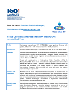
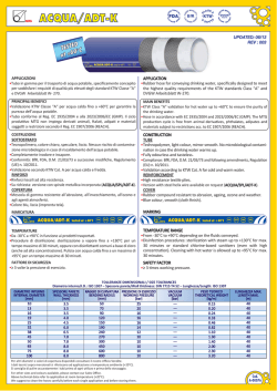
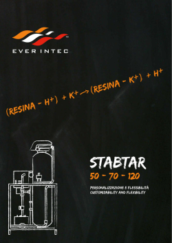
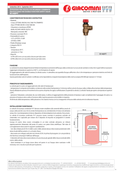
Monteleone M.C., Yeung H. and Smith R. (2007). A review of ancient Roman water supply exploring techniques of pressure reduction.
Water Science & Technology: Water Supply, 7, (1), 113–120.
A REVIEW OF ANCIENT ROMAN WATER SUPPLY
EXPLORING TECHNIQUES OF PRESSURE REDUCTION
M.C. Monteleone*, H.Yeung**, R. Smith***
*
Integrated Waste Management Centre, School of Applied Sciences, Cranfield
University, Cranfield MK430AL, UK [email protected].
** Department of Process and Systems Engineering, School of Engineering, Cranfield
University, Cranfield MK430AL, UK.
*** Integrated Waste Management Centre, School of Applied Sciences, Cranfield
University, Cranfield MK430AL, UK.
ABSTRACT
The Ancient Roman Water Supply System still leaves us astonished when admiring the solidity of the
ruins of aqueducts surviving around Europe. Some parts of these systems are still in use at present and
prove the practical efficiency of Roman hydraulics in the principles acquired from the populations
living in the different regions of the Empire.
In Pompeii the urban water supply system stands as a clear example of the Roman planning of urban
complex networks by using small water towers to serve a limited numbers of users. This allowed to
control the derivations and their maintenance and operated a disconnection from the high pressure
mains and the low pressure pipes, maintaining a fixed maximum height of water over the final points of
discharge.
Considering the techniques for pressure reduction as a method to control leakages, this paper examines
the ancient Roman water supply system to deduce some applications to modern urban networks built in
new establishments.
KEYWORDS
Roman water supply, low pressure water supply systems, pressure control.
INTRODUCTION
The description of the ancient Roman water supply system is contained in some details in the technical
recommendations of the Latin writers Vitruvius (De Architectura, VIII, 1997 translation), Plinio the
Elder (Naturalis Historia, XXXVI, 1988 translation) and Frontinus (De Aquaeductu Urbis Romae, 2004
commentary), Curator Aquarum in Rome from 97 A.D. to 106 A.D.
The water consumption of Rome couldn’t be satisfied by the extraction from
the private and public wells or rainwater harvesting, so Roman kings and
emperors resorted to tap fresh springs in the outskirts of the city, in the
Roman Campagna, to bring their freshness to the urban centre.
The first aqueduct to be built was Aqua Appia, in 312 B.C.and ten more
followed in 540 years, so that by the time of Frontinus appointment to the
office of Curator Aquarum, water in Rome was so abundant that he wrote in
his report on Rome water supply assessment : “With such a quantity of
structures dedicated to water, pyramids in comparison seem idle and Greek
works, though famous, appear inert” (Op. Cit, Par. 16).
Remains are still in place and Roman suburban areas as well as the centre
can offer astonishing views to the traveller (Figure 1, Aqua Claudia,
Romavecchia).
Figure 1. Aqua Claudia at Romavecchia, Rome South East outskirts
Monteleone M.C., Yeung H. and Smith R. (2007). A review of ancient Roman water supply exploring techniques of pressure reduction.
Water Science & Technology: Water Supply, 7, (1), 113–120.
Taking baths became an important habit in Roman life, regardless of the social extraction, so an
increased water supply was needed: ruins of channels or other structures part of the aqueducts exist in all
regions of ancient Roman empire (Figure2, Pont du Gard, Nimes, France; Figure 3, Segovia, Spain;
Figure 4, Merida, Spain).
Figure 2.
Figure 3.
Pont du Gard, Nimes, France
Aqueduct of Segovia, Spain
Figure 4.
Aqueduct of Merida, Spain
(from Perkins, 1994)
The construction of the ancient Roman aqueduct system is in some ways not different from the modern
practice, since often modern technologies descend directly from Roman uses.
More over we can learn some useful lessons from those techniques. Let us consider the urban water
supply system, whose well known example is the one of Pompeii, as will be described later (Richardson,
1989). It is based on low pressure areas, were the head of water (pressure in the mains) maintained after
being conducted from the upstream springs is reduced by means of small local tanks elevated on pillars
and serving a limited number of users.
In the view of the modern techniques for water leakage reduction, comprehensive of pressure
containment methods as outlined in IWA perspective (Brothers, 2005, Thornton, 2003 and Thornton et
al., 2005), and considering the direct relationship between quantity of leaking flow and pressure in the
mains (Smith, 1999), the small local reservoir system can be assessed as a possible method of serving
limited number of customers by means of clean/ reclaimed water tanks connected to single buildings by
gravity mains or pumps.
THE ROMAN WATER SUPPLY SYSTEM
The idea to which the Romans referred when transporting water down to the city was similar to river
flow, in fact they called the channel “Rivus”.The general scheme as it was used in many cities of the
Roman Empire is described in figure 5.
Monteleone M.C., Yeung H. and Smith R. (2007). A review of ancient Roman water supply exploring techniques of pressure reduction.
Closed Conduit
Channel
Water Science & Technology: Water Supply, 7, Open
(1), 113–120.
System
High Pressure
System
System
Collection and Sedimentation Basin
Draining
Channels
Rivus Subterraneus
(Underground
Channel)
Tunnel
Substruziones
(Arches)
Piscina
Limaria
(Settling
Tank)
Low Pressure
System
Bridge
Castellum
Divisorium
(Partition of Flow)
Private Houses
Baths
Castella/ cisternae
(reservoirs)
Figure 5.
Fountains
Castella Privati
(Head reduction to 6
m)
The Ancient Roman Water Supply System.
The search for new springs started as described by Vitruvius (Op.Cit, Book VIII, Chapter 4), to discover
how much wholesome was the water; then `water was collected in a basin, to allow sedimentation as
well (Mucci, 1995)
When water run in soil stratifications, it was made to permeate trough walls with holes and to flow
inside a channel until reaching the basins. Those arrangements are shown in figure 6.
From the collection basin water was flowed into the channels, whose had a rectangular cross section
shape, covered with a masonry vault or slabs of stone positioned in horizontal or roof shape (Corsetti,
1937, Ashby, 1991, Aicher, 1995, Hodge, 2002).
The interior of the channel was lined with hydraulic cement to make it smooth and waterproof.
From the spring down to the city the channel crossed the suburban areas in an open channel flow,
therefore allowing air to be present at all times over the water surface.
The channel was built with almost constant slope of its bottom, varying in its length only in a restricted
range (Lanciani, 1967, Lugli, 1970, Reina, 1917); Vitruvius gives a theoretical value inside the interval
0.0025 and 0.005 m/m.
To maintain the constant slope the “rivus” curved around hills and
valleys, more than crossing them in a straight line, just as a river;
however, when this was not possible, tunnels were excavated and the
bottom of the valleys was crossed with siphons (Hodge, 2002)made
with pressure lead or stone pipes.
The characteristics of the siphons are described in figure 7.
The bottom part was horizontal to avoid more acceleration and abrupt
changes in direction, while stone blocks secured the pressure pipes
along the sides of the valley.
Two tanks at the inlet and at the outlet of the pressure pipes were
built to keep the disconnection with the open channel aqueduct.
This was necessary to allow water to go back at almost the same
eight after passing the valley, that wouldn’t be possible with the open
channel arrangements.
Figure 6. Draining channel and collection basin, Eiffel Aqueduct,
Cologne, Germany (Habery, 1972)
Monteleone M.C., Yeung H. and Smith R. (2007). A review of ancient Roman water supply exploring techniques of pressure reduction.
Water Science & Technology: Water Supply, 7, (1), 113–120.
Whenever the constant slope requirement imposed the channel to run higher than the ground level, it
was built over structures. When the height became considerable, thick walls were substituted with the
use of a succession of arches which could lay in different orders, such as for bridges.
Many sizes and material can be appreciated when visiting the ruin of those arches around the world,
depending on the local materials available and customs. Some examples are shown in figure 8.
Figure 7. Channel crossing a valley: scheme of a siphon arrangement (Hodge, 2002)
Brick faced concrete, Nero’s branch, Rome
Stone blocks without mortar, Pont du Gard, Nimes
Stone masonry, Aqui Terme, Italy
Brick and stone layers masonry, Taormina, Italy
Figure 8. Arches: different shapes and materials of construction.
Monteleone M.C., Yeung H. and Smith R. (2007). A review of ancient Roman water supply exploring techniques of pressure reduction.
Water Science & Technology: Water Supply, 7, (1), 113–120.
During its course the channel reversed its waters to a so called “piscina Limaria”, a settling tank to
avoid transport of particulate impurities downstream (Frontinus, Op. Cit., 19). The shape of the tank
varied (Cagnat, 1916, Pace, 1983) from the simple enlargement of the channel, to the more complex
multi-storey arrangement of piscina of Aqua Virgo (figure 9).
Figure 9. Piscinae Limariae of Aqua Alessandrina, left and Aqua Virgo, right
(Adapted from Piranesi and Cagnat)
Once approached the city the channel was flowing to a partitioning tank, the “Castellum Divisorium”
(Perkins,1994), were it was subdivided in different supply pipes going in separate parts of the city. This
second part of the system, the urban distribution, was a pressure pipe distribution, into lead, terracotta or
wood pipes, depending on the abundance of the materials in the different regions of the empire (Hodge,
2002).
The description of the principle governing the operation of the castellum divisorium is given by
Vitruvius (Op.Cit, Book 8, chapter 6, par. 1–2).) The best preserved examples are Nimes and Pompei
Castella (Richardson, 1989).
Figure 10 reports the plan, picture of the façade and picture of the inside of the building placed in the
highest point of the city, near Porta del Vesuvio.
Figure 10. Castellum Divisorium in Pompeii: Plan, S-E Facade,
View of the interior catwalks and partitioning masonry walls.
The pressure pipe served other reservoirs throughout the city, when the city was much extended in
dimensions (Rome). These “Castella” had, on the contrary of the castellum divisorium, mainly a storage
function, to overcome the fluctuations in the daily consumption.
Other examples of reservoir in the city with a exterior water display functions are the Nimphei and
Naumachie (Cagnat, 1916).
They were huge reservoirs, with an ornamental facade decorated with niches, statues and columns,
through which water was allowed to flow covering multiple cascades and collecting in a large basin at
the bottom of them.
Plan of Side Ninpheum (Asia Minor) and the view of the ruins of a similar construction in Taormina,
Italy, are given in figure 11.
Monteleone M.C., Yeung H. and Smith R. (2007). A review of ancient Roman water supply exploring techniques of pressure reduction.
Water Science & Technology: Water Supply, 7, (1), 113–120.
Figure 11. Side Ninpheum plan (Asia Minor) – from Lanckoronskyand Taormina Naumachia (Sicily, Italy)
From the castella the water run into high pressure pipes to secondary “Castella Privati”, small water
towers, serving a limited number of users public and private (Hodge, 2002) (figure 5).
POMPEII URBAN WATER SUPPLY SYSTEM
A clear vision of the urban water supply system by means of water towers is given by Pompeii ruins.
The castellum divisorium was connected with three mains to the water towers standing along sides of
roads throughout the city.
The outline of the distribution of public fountains, water towers and deep wells is given in figure 13.
The water towers were made of brick masonry 6 metres tall pillars, sustaining a lead tank on their top.
The single users paid to derive some amount of water for their own uses (domus, taberna), but even
public fountains were fed by these towers and were often placed beside them.
The means of metering the water in concession to the users were the calices, bronze orifices (Pace,
1983) connecting the tanks to the single pipes serving each customer. In Pompeii case study they were
placed at the bottom of the lead tanks, with pipes running into cavities left in the brick pillars. Minimum
size of pipe connected was the quinaria pipe, about 2.31 cm in diameter.
Therefore the lead small tank of the water towers acted ad a disconnection between the system at higher
pressure, the mains in the road, and the local low pressure system of the final users.
Castellum Divisorium
Water Tower
Fountain
Deep Well
Figure 12. Pompei Urban Water Distribution System (Adapted from Richardson, 1989)
Monteleone M.C., Yeung H. and Smith R. (2007). A review of ancient Roman water supply exploring techniques of pressure reduction.
Water Science & Technology: Water Supply, 7, (1), 113–120.
For no reasons other than prosecutable behaviour of officers or users water had to be extracted directly
from the major diameter pipes.
The only connection available was through these purpose built water towers or castella private, after
contacting and arranging the consumption quantities with the water office personnel (Frontinus, Op.Cit.,
par. 105 -106).
Looking at this system of water supply to the final point of use it is clear that the pressure built up in the
mains descending from the castellum at the top point of the city was dramatically broken down and
regularised in the water towers tanks ,so that a level of water of about 7 meters, without accounting for
all the pressure losses in the delivering customer pipes, was maintained over the final point of discharge
(figure 14).
Overflow
Calix
Intake
Fountain
6 m
Supply from the
Castellum
House supply
1 m
Water Tower
(Castellum Plumbeum)
House / Shop / Fountain
(Domus/ Taberna/ Munera)
Figure 13. Scheme of Pompei private water supply from water towers
This method was reckoned to reduce the pressure in the mains, because, although it has recently been
demonstrated that Roman lead pipes could bear more hydraulic pressure than they were used for,
Romans were preventing failures of pipes especially due to leakages in the pipes longitudinal joint and
in the various fittings.
A ROMAN WAY TO REDUCE PRESSURE IN WATER SUPPLY MAINS
This Roman urban water supply system gives some hints on a possible method to reduce internal
pressure in water supply mains in newly built housing arrangements.
The mains leading to single apartments could depart from a common local tank situated in an accessible
location, so that pipes with larger diameters and higher pressure running into streets could be left
untouched.
This could give easy life for repairs, and most of all could create a disconnection between the high
pressure network and the users low pressure network. Therefore the number of junctions to the high
pressure loops in the streets, instead of being one per user, could be reduced to one per group of users.
Provision could be made for a tank using reclaimed water for non potable uses, given that in the next
future water can become precious even in countries with a “wet” climate, and that purifications systems
such as membrane filtration allow nowadays a more economic use.
DISCUSSION AND CONCLUSIONS
Comparing the application of the low pressure distribution system to our urban realities, it can be
noticed that modern buildings are in many cases higher than the ancient two stories houses, however
pumps can be available for all sort of conditions allowing many combinations.
Monteleone M.C., Yeung H. and Smith R. (2007). A review of ancient Roman water supply exploring techniques of pressure reduction.
Water Science & Technology: Water Supply, 7, (1), 113–120.
Considered the attention paid to pressure reduction achieved by installing complex devices such as
valves, in existing networks, whose monitoring, maintenance and control arises many different concerns,
the idea of a different “point of use” layout can be assessed.
Issues such as energy consumption or savings, maintenance work, robustness of the system, reliability of
the supply, health and safety concerns, have to be addressed.
Future work can involve the possibility to test local small pressure systems to understand how they can
cope (driven from the past Roman experience) with the modern issues of the urban network realities.
ACKNOWLEDGEMENTS
The authors give particular tanks to Mr. Mario Lo Riso, for practical assistance during the visits to
archaeological sites and to the personnel of the Department of Process and Systems Engineering in
Cranfield University, UK.
REFERENCES
Aicher, P.J. (1995) Guide to the Aqueducts of Ancient Rome. Bolchazy Carducci Publishers, Wauconda,
Illinois.
Ashby, T. (1991) Gli Acquedotti dell’Antica Roma. Quasar, Roma.
Brothers, k.J. (2005). IWA approach to water loss management. Proc. of the IWA Specialized Conference
Leakage 2005, Halifax, 12 -14 September 2005.
Cagnat, R. Chapot, V. (1916–1920) Citernes, Aqueducs, Fontaines et Egouts. In: Manuel d'Archéologie
Romaine. Picard, Paris.
Corsetti, G. (1937). Acquedotti di Roma. Palombi, Roma..
Frontino, G, Commentary by Rodgers, R.H. (2004). De Aquaeductu Urbis Romae. Cambridge University
Press, Cambridge.
Haberey, W. (1972) Die römischen Wasserleitungen nach Köln. Bonn.
Hodge, A.T. (2002). Roman Aqueducts and Water Supply. Gerald Duckworth & Co. Ltd, London.
Lanciani, R. ( 1967 edition). The Ruins of Ancient Rome. Benjamin Blom, New York.
Lanckoronski, C. (1890). Städte Pamphyliens und Pisidiens. Vienna.
Lugli, G. (1970). Itinerario di Roma Antica. Periodici Scientifici, Milano.
Mucci, A. (1995) Il Sistema degli Antichi Acquedotti Romani. F.lli Palombi, Roma.
Pace, P. (1983). Gli acquedotti di Roma e il De Aquaeductu di Frontino. Art Studio S. Eligio, Roma.
Perkins, W. (1994). Roman Imperial Architecture. Yale University Press, Hong Kong.
Plinio the Elder. Translated by A.Corso. ( 1988). Naturalis Historia. G.Einaudi, Torino.
Reina,V., Corbellini,G., Ducci,G. (1917). Livellazione degli antichi acquedotti romani. Tipografia della
Reale Accademia dei Lincei, Roma.
Richardson, L. (1989). Pompeii. The John Opkins University Press Ltd, London..
Smith, E. (1999). The crack opening area for a multiple loading situation. International Journal of
Pressure Vessels and Piping, N. 76, pp. 801 – 802.
Thornton, J. (2003) Managing leakage by managing pressure. A practical approach. Water 21, Magazine of
the international Water Association, October 2003, pp. 43 – 44.
Thornton, J., Shaw, M., Aguiar, M., Liemberger, R. (2005) How low can you go? Practical approach to
pressure control in low pressure systems. Proc. of the IWA Specialized Conference Leakage 2005,
Halifax, 12 -14 September 2005.
Vitruvio, M.P. Translated and discussed by Gros, P.Corso, A. Romano, E. (1997). De Architectura.
G.Einaudi, Torino.
© Copyright 2026 Paperzz