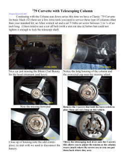
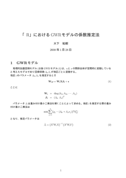
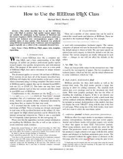
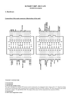
Bulletin 792C Packed Column GC Troubleshooting Guide: How to Locate Problems and Solve Them 792C By applying a systematic approach to troubleshooting, you can solve many GC problems on your own. The real task is identifying the cause of a problem in the shortest possible time. This guide outlines techniques that will enable you to troubleshoot your problem step-by-step. You’ll reduce repair costs and instrument downtime. 5. Detector cleaner A dirty detector creates noisy baselines. Flame ionization detectors (FIDs) can be cleaned by using either FreonВ® TF, an in-place cleaner, or an ultrasonic bath filled with an immersion cleaner. 6. Thermometer To verify the oven temperature, ruling out defective temperature control. Suggestions for Effective Troubleshooting There are five major sources of problems in gas chromatography: (1) the operator, (2) the sample, (3) the column, (4) the equipment or electronics, and (5) the gas flow system. Eliminate these sources in a systemic manner to isolate the cause of a problem. A few basic rules make troubleshooting faster and easier. Most important are maintaining close observation of operating parameters and a good record keeping system (temperatures, flow rates, chart speeds, column type, stationary phase type and amount, solid support type and mesh size, etc.) Also of primary importance are reference chromatograms and reference standards containing known concentrations of the components in your samples, with no extraneous components. Many hours can be wasted hunting problems within an instrument or column, when the problem is, in fact, the sample being analyzed. If your chromatographic system separates the reference standard well and reproducibly, any problem most likely is related to the sample. Your troubleshooting will progress more smoothly if you also have on hand: 1. A duplicate analytical column – one you know will provide acceptable separation under proper conditions Try this duplicate column in your malfunctioning system. If it corrects your problem, the problem is related to the original column. 2. A new syringe, to help isolate the source of ghost peaks Repeat the analysis with a new, clean syringe. If your trouble disappears, the problem is isolated to a defective or dirty syringe used during the original analysis. 7. Spare ferrules To eliminate leaks in connections. 8. Flow meter To check gas flows. 9. Spare recorder and electrometer cables To eliminate the recording system as a source of trouble. 10. Instrument manual Isolating the Problem Source To define your problem, refer to the Symptoms Index on page 4. Locate your trouble symptom (e.g., broad peaks, unresolved peaks, long retention times), then go to the appropriate point in the Troubleshooting Table ( pages 5-18). If there is more than one symptom, note the possible cause for each. If one cause is common to all symptoms, this most likely is the source of your problem. Note that while the troubleshooting table contains most of the symptoms you will encounter, it cannot cover all potential problems. When you cannot find a rapid solution by using the troubleshooting table, you must systematically isolate the trouble by sequentially eliminating the five potential sources of the problem: 1. Rule out operator error by double checking all operating parameters, such as temperature, carrier gas flow, column description, etc. 2. 3. Leak detection aids Use these to ensure that your entire system is free of leaks, as is mandatory for proper operation. We strongly recommend using electronic leak-detecting units, rather than liquids. 4. Spare septa and high temperature septa These help to identify problems with reproducibility or ghost peaks caused by a leaking or bleeding septum. Replace your septum with a new duplicate septum, or with a higher temperature septum. If the symptom disappears, the trouble was a leaking or bleeding septum. SUPELCO Bulletin 792 Check for a sample problem by injecting a reference standard. If you get a good chromatogram, the problem most likely is sample related. If the chromatogram is not satisfactory, the problem probably is column or instrument related. 3. Check for a column problem by replacing the column with a duplicate column, one known to provide good results under proper conditions. If results are good, the problem is related to the original column. If the symptom persists, the problem is related to the instrument. 4. T109792C Isolate equipment related problems by listing the equipment systems which can cause the observed symptoms (e.g., broad peaks with long retention times can be caused by problems in (1) carrier gas system, (2) column heating В©1999 Sigma-Aldrich Co. 1 system, or (3) injection port heating system). Next, isolate the problem by examining each suspected system. Isolate possible electronic system malfunctions (detector, electrometer, recorder, wiring) by performing the following checks. If your instrument is equipped with dual channels (detector, electrometer, recorder, etc.) see paragraph (c). (a) Check the recorder by setting the gas chromatograph attenuation to infinity. The recorder pen should go to electronic zero. If the symptom (baseline drift, noise, etc.) disappears, the recorder is not the problem. If the symptom continues, refer to the recorder instruction manual. (b) To isolate the detector (FID) as the source of trouble, turn off the instrument and disconnect the cable (at the detector end) from the detector to the electrometer. If the symptom disappears when power is on, the problem is in the detector. If the symptom continues, disconnect the same cable at the electrometer. If the symptom now disappears, the cable is defective. If the symptom still continues, refer to the electrometer instrument manual. (Note: To prevent inducing extraneous noise onto the cable, it may be necessary to install a coaxial cap on the free end.) (c) If your chromatograph is equipped with dual detector channels, you have a simple but effective alternate means of identifying the problem source. If the symptom occurs in channel A, disconnect at the detectors the cables which connect channels A and B detector outputs to channels A and B electrometer inputs (Figure A). Reconnect the cable from electrometer B input to detector A output. This applies the signal from the channel A detector output to the channel B electrometer input and recorder. If the symptom does not appear on recorder channel B after this cable change, either the channel A electrometer, recorder, or cable(s) is defective. If the symptom is not eliminated, the channel A detector is the problem source. 5. To check the carrier gas system for possible problems, refer to the following section, Checking the Carrier Gas System. Figure A. Checking for an Electronics Problem in a Chromatograph Equipped with Dual Detector Channels Detector A Alternate Connection When Problem is in Channel A Detector B Electrometer A A typical carrier gas system is illustrated in Figure B. The most common problem in this system is insufficient carrier gas flow through the chromatographic column. This generally is caused by (1) insufficient source pressure, (2) leaks, and/or (3) an unusually large pressure drop across one of the components in the system. Verify the column carrier gas flow at the detector exit, using a flow meter. We do not recommend using a rotameter for measuring gas flow because a specific rotameter is required for each type of gas used, and rotameters exhibit a linear response with pressure changes. When using a bubble flow meter, use the following equation to verify that the carrier gas flow rate is properly adjusted: Time (sec) = Volume Observed (cc) x 60 sec/min Desired Flow (cc/min) Where: Time (sec.) = time required for bubble to travel observed distance. Volume Observed = volume indicated by soap bubble flow meter. Desired Flow = rate specified by method being used. Example: Obtain a flow rate of 20cc/min, using a 10cc soap bubble meter. Time (sec) = 10cc x 60 sec/min 20cc/min Time = 30sec If the time required is not equal to the calculated time, adjust the carrier gas flow rate. If sufficient flow cannot be obtained by adjusting the flow control valve, the problem probably is due to inadequate source pressure (measured at P1 in Figure B). Increasing this pressure usually will provide adequate flow. Normally, a source pressure of 60psig is sufficient for 6-12 foot columns. Increasing the column length, oven temperature, and/or flow rate will require raising the source pressure. The source pressure is particularly important if you are using a temperature program, since the pressure must be 10-15psig in excess of the column pressure drop at the maximum temperature. This pressure difference allows the differential flow controller to function properly. If the correct pressure difference is not maintained, carrier gas flow will drop drastically at elevated temperatures. Other common causes of inadequate gas flow are leaks in the system and a large pressure drop across one or more of the system components. The use of pressure gauges can save considerable time when isolating these problems. Common leak points are column connections, the septum, and connections for the various valves and gas purifiers. Recorder A A pressure gauge installed between the flow control valve injection port (P3 in Figure B) indicates column head pressure. A low reading at this point indicates a leak between P3 and the detector outlet (e.g., a defective column, septum, etc.) or a large pressure drop across an upstream component (e.g., a plugged gas purifier). Alternatively, an OMIв„ў Indicating Purifier will tell you at a glance whether leaks are present (see products pages). A high pressure reading at P3 indicates an over-tightened septum, dirty detector, too-tightly packed column, etc. Low pressure readings on a pressure gauge at P2 will reveal an exhausted High Capacity Gas Alternate Connection When Problem is in Channel B Electrometer B Checking the Carrier Gas System Recorder B 712-0082 2 SUPELCO Bulletin 792 your column in two ways: allowing the column to cool before turning off the carrier gas prevents oxidation of the column packing, which can occur when a hot column is exposed to oxygen in the air. Allowing the column pressure to drop to ambient pressure prevents the packing from blowing out of the column ends. A sudden change in pressure, when a column or a septum is removed with the carrier gas flowing, can blow packing from the column. Purifier (larger than normal pressure drop). Routine observation of this pressure will enable you to determine when the gas purifier should be changed. NOTE: Many chromatographs have an intentional crimp in the carrier gas line between the flow controller and the injection port, or employ capillary tubing with a small internal diameter. Consequently, the pressure reading at point P3 will be different from the column head pressure reading taken through the septum. These restrictions also can make it difficult to obtain sufficient carrier gas flow, particularly when converting an instrument for use with capillary columns. NOTE: When storing columns, cap the ends with metal SwagelokВ® caps to prevent diffusion of air into the column (and subsequent oxidation). Plastic caps do not prevent diffusion of air into a column. Testing for Leaks Sample Injection The most common method of leak testing is to apply a liquid (e.g., SnoopВ® or HT-Leak Detector) and watch for bubbles to appear. These liquids can be aspirated into the GC system, however, and can cause unstable baselines and ghost peaks in subsequent chromatograms. To eliminate the risk of contamination, use a thermal conductivity leak detector, such as a GOW-MAC unit. These units are extremely sensitive to helium or hydrogen leaks, and are equal to liquids in sensitivity for nitrogen and other heavy gases. Improper sample injection can cause many problems in gas chromatography. To ensure that your injections are accurate and reproducible, we recommend the following general guidelines and procedures: A. Syringe Size: Always use a syringe large enough that the desired sample volume does not fill it to capacity, and small enough that the sample volume is not less than approximately 10% of its capacity. B. Injection Technique: Sample injection should be smooth and rapid, with quick removal of the syringe after injection, in order to avoid peak broadening. A simple technique for detecting septum leaks, while avoiding contamination, is to use a Supelcoв„ў Leak Tester – a plastic tube with conical ends. When one end is dipped in Snoop, capillary action pulls a small amount of the liquid into the tube. If a leak is present, bubbles appear at this end when the opposite end is pressed against the septum nut. Because the liquid does not contact the instrument, there is no risk of contamination. C. Sample Size Reproducibility: Many problems in chromatography result from difficulties in reproducing the size of a sample. Some techniques which will help ensure reproducible samples are: 1) Automatic Injectors: These devices improve sample reproducibility by virtue of consistent mechanical operation. Each step (sampling, sample injection, syringe cleaning) is repeated precisely. Problems Related to Column and Septum Removal and Installation Improperly installed columns and septa are a frequent source of leaks, and are the most common cause of glass column breakage. An incorrectly tightened septum nut presents problems such as excessive septum bleed, premature septum leaks, and low carrier gas flow rates. We offer two torque wrenches to help ensure correct installation of columns and septa. The Glasrenchв„ў, used for installing columns, is available in two torque settings to provide the correct torque for the various types of ferrules. The Supelco septum nut torque wrench ensures that the correct torque is consistently applied when installing septum nuts. These tools save time and money by eliminating over-tightening, minimizing leaks and column breakage. 2) Sampling Valve Injection: Sample size is determined solely by sample loop size, and injection is rapid and precise. Reproducibility is improved because chances for variability are greatly reduced. 3) Solvent Flush Technique: This technique (Figure C) reduces the problem of irreproducible injection volumes when making syringe injections by hand. a) Eliminate sample hang-up in the needle by first cleaning the syringe, then drawing in a small aliquot of solvent. When changing columns or septa, it is important that you first turn off the chromatograph oven and allow the column to cool for 1015 minutes, then turn off the carrier gas. This procedure protects b) Remove the syringe from the solvent and draw in a small amount of air. c) Draw in the desired amount of sample. Figure B. Typical Carrier Gas System P1 Septum P2 Moisture Trap Carrier Gas Source Oxygen Trap P3 Particle Trap Flow Control Valve Ideal Location Injection Port Detector Typical Location OMI Indicating Purifier *NOTE: Our High Capacity Gas Purifier combines the functions of a moisture trap and an oxygen trap (see products pages). SUPELCO Bulletin 792 Column G001131 3 d) Remove the syringe from the sample and draw in a little more air. Gas Chromatography Troubleshooting Table e) Verify the amount of sample in the syringe barrel. This is only possible with syringes that do not have plungers in the needle. ECD – electron capture detector f) Quickly and smoothly inject sample into the chromatograph. NPD – nitrogen phosphorous detector 4) Syringes with Needle Plungers: Improve sample reproducibility by using a syringe with a plunger in the needle. This eliminates sample retention in the needle dead volume. The solvent flush technique, above, may be useful, since a small amount of sample hang-up can still occur. Figure C. Solvent Flush Technique Air Plunger Solvent Air Air Plunger Sample Solvent G001132,1 133 Other Useful Publications In addition to the information presented in this guide, helpful tips to save time and money in chromatography are offered in the following FREE Supelco technical literature: Bulletin 741 The ideal ferrule provides a leak-tight seal, accommodates column OD variations, seals with minimum torque, and does not stick to the column or fitting. This bulletin offers valuable information about choosing the best ferrule for various applications. Bulletin 783 Provides instructions for cleaning dirty flame ionization detectors (FIDs) and offers hints to help prevent contamination. Abbreviations FID – flame ionization detector FPD – flame photometric detector TCD – thermal conductivity detector Symptoms Index Symptom Baseline changing cycling dip drift drop noise off scale (zeroing problem) rise spikes, irregular spikes, regular Carrier Gas low flow rate Column Life short Column Packing compacted gaps in Detector Response low Peak Shapes Incorrect cigar top clipped round top skewed (leading edge) split square top tailing Peaks broad (solvent) missing (all) missing (some) negative random extra peaks sample memory peaks unresolved Quantification irreproducible Retention Time prolonged or shortened Symptom No. 23 9 25,26 7 24 8 6 22 11 10 32 33 31 30 3,4 20 21 19 16 17 18 15 27 1 2 12 14 13 29 5 28 Bulletin 898 Provides valuable information about installing and troubleshooting gas delivery systems for single GC or multiple GC systems. Bulletin 918 The best gas purifier system includes multiple purifiers that help protect each other while protecting columns and detectors. This bulletin includes information needed to select suitable purifiers for carrier gas, and for air and hydrogen used as fuel gases. Publication 395082 Leak-resisting, low bleed septa improve baseline stability and reduce the occurrence of leak-associated problems. This publication describes tests that show Thermogreen LB-2 septa exhibit low bleed at inlet temperatures up to 350В°C. 4 SUPELCO Bulletin 792 Troubleshooting Table Symptom Symptom No. 1: No Peaks Possible Cause 1. S 3. Detector or electrometer power off / fuse blown. Sample injected in wrong column (multiple-column chromatograph). FID not lit. 4. No carrier gas flow. 5. 6. Defective syringe. Column or septum leak. 7. Injection port temperature too low – sample not vaporized. 8. Defective recorder. 9. Defective detector, electrometer, or cable. Bad connection between FID collector and voltage source. 2. Normal Problem 795-0314 10. Remedy 1. Check detector, electrometer settings, and fuses. 2. Reinject sample in proper column. 3. Use mirror over exhaust to check FID. If lit, water condenses on mirror. If not lit, light flame. Check hydrogen and air flows. 4. Measure flow at detector or column exit. If no flow, check for leaks or obstructions at column connection and septum. 5. Replace syringe. 6. Replace septum. Check column connections. 7. Increase injection port temperature (but not in excess of liquid phase temperature limit) or inject sample directly onto column packing. 8. Check recorder connections. Check recorder zero. Troubleshoot recorder according to instruction manual. 9. Check collector voltage and connections per instrument manual. 10. Check collector spring clip connection. Symptom No. 2: Missing Peaks / Solvent Peak Only 1. Sample too dilute. 1. 2. Column or septum leak. 2. 3. Incorrect temperatures: (a) Injection port or column temperature too low, sample not vaporized. 3. (a) Ensure column temperature setting is correct for column being used and sample being analyzed, then verify that oven is operating at selected temperature. Increase temperature if necessary. (b) Decrease injection port temperature. Normal (b) Injection port temperature too high for thermally labile compounds. 4. (c) Column temperature too high, sample eluting in solvent peak Flow rate incorrect. (c) Decrease column temperature. 4. 5. Sample adsorption by column or glass wool. 5. 6. Column cannot separate components from solvent. 6. Problem Check system by injecting standard. If okay, increase sensitivity or inject larger or more concentrated sample. Check for leaks (see page 3). Tighten connections. Replace septum. 795-0315 Measure flow rate, adjust if necessary (see page 2). Inject standard on known good column. If okay, original column is bad. Use properly treated glass wool (i.e., H3PO4 for free acid analysis, siliconetreated for other compounds). If sample has never been analyzed and is chemically active, you may need a special column. Change column or solvent. Problem 795-0317 SUPELCO Bulletin 792 5 Symptom Possible Cause Remedy Symptom No. 3: Low Detector Response (all peaks; retention times correct) 1. Poor injection technique. 1. 2. Sensitivity setting wrong or sample too small. Defective syringe. Septum leak. Injection port temperature too low for sample. FID only: low hydrogen flow or air flow incorrect. FID only: low oxygen level in compressed air. FID only: faulty connection between FID collector and voltage source. Dirty ECD. For TCD: (a) Carrier gas flow rate incorrect. (b) Cell voltage incorrect. Sample adsorbed by column, glass wool, tubing, etc. FPD only: hydrocarbon eluting with sample, causing diminished response due to quenching effect. 2. 3. 4. 5. 6. 7. Normal 8. 9. 10. 11. 12. Problem 795-0316 3. 4. 5. Use correct syringe size; use solvent flush technique (see pages 3 and 4). Check, correct if necessary. Inject standard for comparison. Use new syringe. Replace septum. Increase injection port temperature. 6. Measure flows, correct if necessary. 7. Replace air tank. 8. Clean collector spring clip with emery paper. Clean per instrument manual. (a) Measure flow, adjust if necessary (see page 2). (b) Refer to instrument manual. Use deactivated column materials. 9. 10 11. 12. Check with hydrocarbon free standard; change to column that will separate hydrocarbons from components of interest. Symptom No. 4: Low Detector Response (all peaks; retention times too long) 1. Low carrier gas flow rate. 1. 2. Carrier gas leak at septum or column connections. Column temperature too low. Column worn out or conditioned at too high a temperature. 2. 3. 4. Normal Problem 6 3. 4. Measure flow, adjust if necessary (see page 2). Check for leaks, correct if necessary (see page 3). Increase column temperature. Verify column temperature and stationary phase temperature limits. Analyze sample on known good column. Repack first 6" of column or replace column. 795-0316 SUPELCO Bulletin 792 Symptom Possible Cause Remedy Symptom No. 5: Quantification Not Reproducible a. b. c. Retention times correct. Components with longest retention times show low values when using normalization techniques. 1. e. Low values for minor compounds. f. Increased peak response with successive injections. Verify using known standard. a1. Use solvent flush technique (see pages 3 and 4). a2. Increase temperature a3. Adjust slope sensitivity. b1. Determine correction factors and/ or use internal standards technique. b2. Use deactivated system. b1. Differing detector response for different components. b2. Adsorption of components by packing, glass wool, tubing, or transfer lines c1. Internal standard not compensating for all components in sample. c2. Slope sensitivity of integration not high enough for late eluters. d. Insufficient resolution of peaks, or peak tailing. Quantification varies for one component eluting over wide time span, even using internal standard technique. Inconsistent quantification for same sample on successive analyses. 1. a2. Injection port or column temperature too low. a3. Incorrect slope sensitivity with electronic integrator. Retention times correct. Different components not yielding similar peak areas for same amount. d. Wrong sample. a1. Incomplete sample injection. c1. Use multiple internal standards. c2. Use multiple internal standards. d. Modify operating parameters or replace column to improve resolution and eliminate tailing. e. Increase sample size or electrometer range setting. f. Use deactivated system. e. Sample too small for accurate counting by integrator. f. Adsorption of components and saturation of active sites with sample (priming the column). Symptom No. No. 6: 6: Baseline Baseline Off OffScale, Symptom Scale, Cannot Zero 1. Column not conditioned properly, or contaminated, or temperature too high. 1. 2. Recorder problem. 2. 3. Septum leak. 3. 4. 4. 5. Wrong gas (e.g., argon/methane with FID). Contamination. 6. Too much/too little gas flow. 6. 7. 8. TCD: imbalance in column flow. Contaminated detector (e.g., NPD contaminated with Snoop, ECD contaminated with chlorinated solvents). Electrometer or detector problem. 7. 8. Reduce column temperature to ambient. If baseline normal, check system with good column. If okay, recondition original column. Set attenuation to infinity. If recorder does not go to electrical zero, troubleshoot recorder per manual. Check for leaks, correct if necessary (see page 3). Verify gases are correct for instrument and detector as specified in manual. Turn off injection port heat. If zeroing capability returns, clean injection port liners, etc. Check flow, adjust to within manual specifications. Check flow, adjust as necessary. Avoid sources of contamination. 9. Troubleshoot per instrument manual. 100 0 Normal 5. 100 Problem 795-0318 0 9. SUPELCO Bulletin 792 7 Symptom Possible Cause Remedy Symptom No. 7: Baseline Drift 1. Carrier gas flow changing with temperature during emperature programming. Septum or column leak. 1. Increase source pressure to 15psig above column head pressure. 2. Septum bleed or septum fragments in column. Column bleed or contamination. 3. Gas flows not within minimum/ maximum limits (including hydrogen and air for FID) or poorly related flow. Insufficient instrument warm-up time or temperature equilibration time. 5. Check, correct as necessary (see page 3). Replace septum with higher temperature type; repack column inlet. Replace column with known good column. If results okay, recondition original column. Measure flows and verify against manual specifications. 7. Defective electrometer or detector. 7. 8. Contaminated detector or injection port. 8. 2. 3. 4. 5. Normal 6. 4. 6. Allow time for instrument to equilibrate when changing operating temperature or installing another column. Troubleshoot per Isolation of Problem Source (see page 1). Clean as recommended in instrument manual. Problem 795-0319 Symptom No. 8: Irregular or Unstable Baseline (baseline nosie) Normal Problem 1. Column bleed or contamination. 1. Replace column with known good column; if results okay, recondition original column. 2. Contaminated detector or injection port. 2. Clean detector and/or injection port. 3. Carrier gas leak. 3. Check for leaks, correct as necessary (see page 3). 4. Poor carrier gas regulation. 4. Check gas supply for sufficient pressure. Replace tank if near empty. 5. Gas impurities/contaminated gas line. 5. Change gas tank, clean metal tubing, use gas purifier(s). 6. Gas flows not within minimum/ maximum limits (including hydrogen and air for FID) or poorly regulated flow. Defective electrometer, detector, or cable. 6. Measure flows and verify against manual specifications. 7. Troubleshoot per Isolation of Problem Source (see page 1). 8. FID only: collector incorrectly aligned. 8. Realign as required. 9. ECD only: heater wire too close to detector wire, causing AC noise. 9. Reposition heater wire. 7. 795-0323 8 SUPELCO Bulletin 792 Symptom Possible Cause Remedy Symptom No. 9: Cycling Baseline Drift 1. Poor instrument location (drafts, changes in ambient temperature, etc.). Defective detector temperature controller. Defective oven temperature controller. Carrier gas flow irregular: insufficient supply pressure. Defective carrier gas regulator. Defective carrier gas flow controller. 1. 7. 2. Close windows, relocate instrument, etc. Replace temperature sensing probe. 3. 4. Replace temperature sensing probe. Change gas tank. 5. 6. Replace regulator. Replace flow controller. If using pumped gases, such as from hydrogen generator: sensitivity too high. 7. Reduce detector sensitivity or decrease output pressure from generator. 1. Condensate or dust particles in FID. 1. 2. Contaminated gases. 2. 3. Defective electronics or detector 3. Clean detector, check column ends to ensure glass wool is in place. Replace gases or insert liquid nitrogen trap in gas line. Check recorder cables and detector/ electrometer cables. Troubleshoot electronics and detector per Isolation of Problem Source (see page 1). 1. 2. Defective cable, intermittent shorting. ECD: heater wire and detector wire too close, or loose. FID: insufficient hydrogen flow. Electronic interference from external source. 1. 2. Recorder improperly connected, polarity reversed, or sample injected into wrong column. TCD only: impurity in carrier gas. 1. Reverse recorder connections or polarity switch. 2. Install or replace carrier gas purifier(s). 2. Normal 3. 4. 5. 6. Problem 795-0324 Symptom No. 10: Spikes (regular) Normal Problem Problem 795-0320 Symptom No. 11: Spikes (irregular or erratic) 3. 4. Normal Problem 3. 4. Replace cable. Check wire position, relocate if necessary. Increase flow. Relocate instrument, determine possible interference sources (nearby transmitter site, etc.). 795-0321 Symptom No. 12: Negative Peaks 1. 2. Normal Problem SUPELCO Bulletin 792 795-0322 9 Symptom Possible Cause Symptom No. 13: Extra Peaks (peaks similar to previous sample appear when solvent alone is injected) 1. Dirty syringe. 1. 2. Column adsorbing, then desorbing sample (particularly in temperature program). Adsorption in transfer line. 2. 3. Remedy Try new syringe and clean solvent. If extra peaks disappear, clean syringes more thoroughly. Use more inert column materials (tubing, packing, glass wool). 3. Use glass-lined stainless steel for transfer lines. Turn off injector heater. If extra peaks disappear, operate at lower injector temperature or use high temperature septa. Let analysis run longer, then repeat. Previous Sample Normal (solvent injected after sample) Problem (solvent injected after sample) 795-0336 Symptom No. 14: Extra Peaks (unlike peaks in previous sample) 1. Septum bleed, particularly in temperature program. 1. 2. Peaks from previous runs, particularly if very broad with short retention time. Impurities from sample, solvent, sample container (e.g., plasticizer from cap liners or contaminated glassware), labware, or reagents used in sample preparation, particularly when excess reagents are concentrated in work-up. 2. 4. 5. Condensed carrier gas impurities eluting during temperature programming. Trace impurities in lab atmosphere. 6. Air peaks or water peaks. 6. 7. Multiple or incomplete derivatives formed in sample work-up. Sample decomposition. 7. 3. Normal 4. 3. 5. Problem 8. 8. Run solvent blank with clean syringe. If extra peaks appear, change solvent; if no extra peaks appear, run solvent blank through entire sample work-up. If no extra peaks appear, impurities are from sample. If extra peaks appear, repeat analysis of solvent blank for each step of work-up to isolate source. Install or replace carrier gas purifier(s). Analyze lab environment, take corrective action as necessary. Normal with TCD, using syringe injection or aqueous samples. Re-evaluate derivatization procedure. Reduce temperature and/or use different column. Problem 10 SUPELCO Bulletin 792 Symptom Symptom No. 15: Tailing Peaks Possible Cause Remedy Column or injection port temperature too low. Column deteriorating. 1. 3. Active sample adsorbing on injection port, transfer lines, column, or glass wool. 3. 4. Two compounds co-eluting. 4. 5. Needle hitting packing in column inlet (breaks particles and creates active sites). 5. 1. Column overload. 1. 2. Two components co-eluting. 2. 3. Sample condensation. 3. 4. Sample decomposition. 4. 1. 2. 2. Normal Increase temperature (do not exceed maximum temperature for column). If retention times have not changed from when column was new, replacing first 6" of packing or replacing precolumn may help. If retention times have changed, replace column. Use more inert system: all glass, TeflonВ®, specially designed packing, on-column injection, proper glass wool type, etc. Increase sensitivity, reduce sample size, reduce temperature approximately 20В°C, look for partial separation. Remove several cm of packing from inlet. Problem 795-0339 Symptom No. 16: Leading Peaks Normal Problem SUPELCO Bulletin 792 Decrease sample size or select another column with higher stationary phase loading. Alternatively, select a different stationary phase with greater solubility for the component exhibiting this behavior. Increase sensitivity, reduce sample size, reduce temperature approximately 20В°C, look for partial separation. Check injection port and column temperatures, increase if necessary. Use inert system and deactivated packing. 795-0340 11 Symptom Symptom No. 17: Split Peaks Possible Cause Remedy 1. 2. Gross detector overload. Sample flashing prior to injection – simulates two injections. 1. 2. Reduce sample size. Use solvent flush technique, so sample is contained in barrel, not in needle (see pages 3 and 4). Use less volatile solvent. 1. 1. Reduce sample size. 2. Electrometer saturated (normal for solvent). Recorder defective. 2. Troubleshoot per instruction manual. 1. 2. FID: detector overload. Recorder gain too low. 1. 2. Decrease sample size. Adjust control. Normal Problem 795-0341 Symptom No. 18: Squared (Flat-Topped) Peaks Normal Problem 795-0342 Symptom No. 19: Round-Topped Peaks Normal Problem 795-0343 12 SUPELCO Bulletin 792 Symptom Symptom No. 20: Cigar-Top Peaks Possible Cause ECD: detector overload. Remedy Reduce sample size. Normal 795-0344 Problem Symptom No. 21: Clipped Peaks – Column Efficiency Exceptionally High Recorder or instrument zero below minimum moveable range of recorder pen. Shunt recorder leads and set recorder baseline adjustment zero to approximately 5% of full scale. Normal Problem 795-0345 Symptom No. 22: Baseline Rise Before or After Peak Sample decomposition. Use inert column and packing. Normal Problem Problem 795-0346 SUPELCO Bulletin 792 13 Symptom Symptom No. 23: Baseline Change After Large Peak 1. 2. 3. Possible Cause Contamination – water or large component stripping contaminants from column. Column not conditioned properly – liquid phase being stripped. Pressure imbalance when gas sampling valve activated. Remedy 1. Repack first 6" of column or replace pre-column. 2. Recondition column. 3. Correct pressure imbalance. Decrease sample size. Check and adjust carrier gas, hydrogen, and air. Clean or replace flame tip. Adjust collector position. Normal Problem Problem 795-0347 Symptom No. 24: Baseline Drop After Peak (FID only – flame extinguished) 1. 2. Sample too large. Incorrect gas flows. 1. 2. 3. 4. Flame tip plugged. Collector and flame tip not located properly (whistling or humming noise often heard). 3. 4. Normal Problem 795-0348 14 SUPELCO Bulletin 792 Symptom Symptom No. 25: Negative Dips After Peaks Possible Cause 1. 2. Only after large peak such as solvent: sample too large. After all peaks with ECD: dirty detector cell. Remedy 1. Decrease sample size. 2. Clean detector. Normal Problem 795-0349 Symptom No. 26: Negative Dip Before Peak Pressure imbalance when gas sampling valve activated. Correct pressure imbalance. Normal Problem G0001158 Symptom No. 27: Broad Solvent Peaks 1. Dead volume in injection port due to poor column installation. 1. 2. Normal with very dilute sample, as in trace analysis. Poor injection technique. 2. Injection port temperature too low. Sample solvent interacts with detector. Sample solvent retained by column (e.g., methanol by active column). 4. 5. 6. 3. 3. Normal 4. 5. 6. Problem SUPELCO Bulletin 792 Use on-column injection. Ensure proper column connections, particularly when changing from one column diameter to another. — Make smooth, rapid injections (see page 3). Increase injection port temperature. Change sample solvent. Change sample solvent. 795-0350 15 Symptom Symptom No. 28: Retention Time Longer / Shorter On Same Column Possible Cause Remedy 1. Column temperature too high/too low. 1. 2. Carrier gas flow rate too low/too high. 2. 3. 4. Septum or column leak. Column contamination or deterioration. 3. 4. 5. 6. Recorder problem. Sample overload. 5. 6. 1. 2. Column too long/too short. More/less packing in column due to: a.Support density greater/less than previously used. b.Column packed more tightly/ loosely. c.Column inside diameter greater/ smaller. Too much/too little stationary phase on support, due to different manufacturing procedures or to errors. Stationary phase different, or variation in phase composition (particularly common with commercial chemicals not manufactured for GC). Support type different. Check temperature with independent thermometer, adjust as necessary. Measure rate with soap bubble flow meter at column exit, adjust as necessary. Check, correct as necessary. Repack first 6" of column, or replace column. Check recorder chart speed. Reduce sample size. Normal Problem Problem 795-0351 On New Column (compared to previous column of same composition) 3. Normal 4. 5. Use tested, standardized columns and packings. Problem Problem 16 795-0352 SUPELCO Bulletin 792 Symptom Symptom No. 29: Unresolved Peaks Possible Cause On Column Which Previously Produced Good Results 1. 2. 3. 4. 5. Wrong column temperature. Wrong carrier gas flow rate. Sample problem: a. Sample too large. b. Sample concentration different from previous analysis – minor peak “swamped” by major peak. Poor injection technique (slow). Column contaminated or deteriorated. Normal Remedy 1. 2. 3. Check and adjust temperature. Check and adjust flow rate. a. Reduce sample size. b. Reduce sample size. 4. 5. Make smooth, rapid injections. Repack first 6'” of column, or replace column. 795-0356 Problem Problem 795-0354 After Previous Column of Same Composition Produced Good Results 1. 2. 3. Normal 4. 5. Column too long/too short. More/less packing in column due to: a. Support density greater/less than previously used. b. Column packed more tightly/loosely. c. Column inside diameter greater/ smaller. Too much/too little stationary phase on support, due to different manufacturing procedures or to errors. stationary phase different, or variation in phase composition (particularly common with commercial chemicals not manufactured for GC). Support type different. Use tested, standardized columns and packings. Problem Problem SUPELCO Bulletin 792 795-0355 17 Symptom Possible Cause Symptom No. 30: Large Gaps Appear In Packing (visible in a glass column) Column improperly packed. Remedy Add enough packing to fill voids, then gently vibrate until smooth. If this does not solve problem, repack column. Symptom No. 31: Packing Compacts or Shirks After Conditioning 1. 2. Slight compacting may occur when packings are exposed to pressure. Significant compacting (bed contracts 3" or more). 1. Normally not a problem – use column. 2. Column may not be properly packed. Add more packing. Overtightened septum. Insufficient carrier gas source pressure. Insufficient source pressure for temperature program. 1. 2. Loosen septum. Increase pressure by 10psig. 3. Plugged injection port, carrier gas line, or gas purifier(s). Column over-packed or glass wool too tight. 4. Flow control must have 10-15psig higher than maximum pressure (reached at maximum temperature) to function properly. Replace tubing or gas purifier(s) as necessary. Increase carrier gas pressure. If flow still insufficient, install another column. (Note: not all packings have same pressure drop.) If flow okay, original column was problem. If flow low, check plumbing system for flow restrictions (plugged detector, plugged gas filter, etc.). Symptom No. 32: Low Carrier Gas Flow/Large Pressure Drop 1. 2. 3. 4. 5. 5. Symptom No. 33: Column Deteriorates Too Soon After Installation (peaks tail, are poorly resolved, etc.) 1. Column operated near or above maximum temperature limit of packing. 1. 2. Water or oxygen in carrier gas contaminating column. 2. 3. Column leaks causing contamination by oxygen. 3. 4. Column damaged by aqueous samples, serum, plasma, other complex samples. These samples can (1) strip phase from support, (2) chemically react with phase, (3) build up on column and possibly destroy it, injection end first. 4. Normal Problem 18 795-0356 Use higher temperature phase. Use shorter column and lower temperature, if possible. Reduce temperature when column not in use. Remove column from oven when another column is used at higher temperature. Use carrier gas purifier(s) and appropriate grades of gases. Replace tanks before pressure becomes too low (300psig). Check for leaks prior to use. Always allow column to cool before removing from GC, to prevent exposing a hot column to air. Use precolumns or repack column inlet to extend column life. SUPELCO Bulletin 792 Septum Nuts Thermogreenв„ў LB-2 Septa в—Џ Extremely low bleed from 100В°C to 350В°C в—Џ Already conditioned, ready to use в—Џ Easier needle penetration, high puncture tolerance Disc Diameter mm Inch Qty. 5.0 3/16 50 6.0 1/4 50 1 3/8 50 9.5 9.5 1 3/8 250 9.5 1 3/8 1000 10.0 13/32 1000 11.0 7/16 50 11.0 7/16 250 11.0 7/16 1000 11.5 11/24 50 12.5 1/2 50 12.5 1/2 250 14.0 9/16 50 16.0 5/8 50 17.0 21/32 50 Cylindrical, for ShimadzuВ® instruments Plug Type 10 Plug Type 50 Drilled, for Solid Phase Microextraction 9.5 1 3/8 25 9.5 1 3/8 50 11.0 7/16 25 11.0 7/16 50 1 Cat. No. 20638 20651 20652 20666 20677 23157 20654 23163 23164 23154 20660-U 20678 20662-U 20663 23159 20608 20633 23161 23162-U 23167 23168 We recommend a 9.5mm (3/8") septum to those who previously used the 9mm size. Thermogreen LB-1 Septa в—Џ Inlet temperature: 50В°C to 300В°C Disc Diameter mm Inch 9.5 10.0 11.0 12.5 3/8 13/32 7/16 1/2 Qty. 50 50 50 50 Cylindrical, approx. 6mm diameter x 9mm Thru-Hole Type 100 Half-Hole Type 100 The needle guide in Supelco septum nuts ensures that the needle consistently penetrates the septum in the same place, prolonging septum life. The guide also prevents the needle from striking the edge of the column or bending during insertion. The 9/16" hexagonal nut head accommodates our torque wrench for consistent, optimum tightening. Each nut is supplied with easily interchanged 1/2" and 1" guides. Use 9.5mm septa P00261 with each nut. The stainless steel nuts hold up under heavy use (e.g., when septa are replaced daily). We also recommend using them for reactive samples, such as chlorinated pesticides. Aluminum nuts offer economy in light use or when samples are nonreactive (i.e., when metal columns are used). Nut N-1 fits PE-3920, 900, Sigma series, HP-5700, other ports accepting 1/4" Swagelok nut, 7/16" threads, 20/inch. Nut N-2 fits Varian 3700, other ports accepting 1/4" nut, 7/16" threads, 24/inch. Use with packed columns only. Description Septum Nut N-1 Stainless Steel1 All Aluminum Septum Nut N-2 All Aluminum 1 Cat. No. 20659-U 20657-U 20658 20661 Cat. No. 22399 22497 22402 Aluminum needle guide. Torque Wrench 20667 20668 Pyrosepв„ў S-1 Septa Inlet Temperature: 300В°C to 400В°C. Because they are relatively hard, Pyrosep S-1 septa must be used with a needle guide (to prevent the needle from buckling) and only at high temperatures. Disc Diameter mm Inch 6 1/4 9.5 3/8 Adapter Rings (pk. of 2) 9.5mm OD x 6mm ID1 11mm OD x 9.5mm ID2 12.5mm OD x 9.5mm ID3 1 2 3 Qty. 10 10 Use with 6mm septa, to replace 9.5mm septa. Use with 9.5mm septa, to replace 11mm septa. Use with 9.5mm septa, to replace 12.5mm septa. SUPELCO Bulletin 792 Cat. No. 22369 22370-U 22338 22607 22340-U 9130363 The handle of the Supelco septum nut torque wrench slips when preset torque (8 inch-lbs.) is reached. Helps prevent leaking septa, excess bleed, and difficult septum penetration. Deepwell socket (9/16") fits over the Supelco septum nut even with a needle guide attached. Description Cat. No. Torque Wrench 22661 19 Select the best ferrule for your application: Supeltexв„ў ferrules form leaktight seals without sticking to your column. And they don’t require back ferrules. We highly recommend: в—Џ Supeltex M-4 and Supeltex M-2A ferrules for glass columns в—Џ Supeltex M-2A and Supeltex M-2 ferrules for metal columns 22492 P000182 Ferrule Max. Temp. Characteristics Supeltex M-1 ceramic-filled Teflon 250В°C Ideal for connections to mass spectrometers. High reusability Isothermal use only Supeltex M-2 du Pont VESPELВ® SP-1 (100% polyimide) Supeltex M-2A du Pont VESPEL SP-21 (85% polyimide/15% graphite) 350В°C High reusability 400В°C Seals at 1/4 turn past fingertight. High reusability Won’t stick to metal or glass. Supeltex M-2B du Pont VESPEL SP-211 (10% Teflon graphite/75% polyimide) Supeltex M-4 flexible graphitere O-Ring silicone 350В°C Conforms easily to capillary column, ensuring an effective seal and less chance of breakage. 450В°C Seals at 1/4 turn past fingertight. Maximum sealing surface contact, reduced risk of column contamination at installation. Seals column having OD over or under specifications. 200В°C Supeltex Ferrules for Packed Columns Supeltex Ferrule Type (Temp. Limit) M-1 (250В°C) M-2 (350В°C) M-2A (400В°C) Indented Blank1 1/4" Cat. No. Glasrench Wrench 1/16" Cat. No. Qty. 22086-U 22087-U 22320-U 22475 22481 22471 22089 – – – 22393 – 22496 22309 22321 22476 22483-U 22472 22386 – 20644-U – 22487-U – 10 100 10 50 10 50 – 22492 22478 – 22493 – – 22491 – 22488 22495 – 10 10 50 20407 1/4" – 6mm 20406 1/8" – 1/16" 100 M-4 (450В°C) O-Rings (200В°C) Ferrule ID: 1 Column OD 6mm 1/8" Cat. No. Cat. No. Leak Tester Kit Eliminates placing leak detection fluid, a potential contaminant, directly onto the septum. Dip one end of the leak tester tube into Snoop and place the other end into the septum nut or needle guide. Bubbles indicate a leak. Kit includes 10 leak tester tubes and 8 ounces of Snoop. Leak-TecВ® Leak Detector Use at temperatures up to 210В°C – Leak-Tec leak detector will not bubble on a heated part unless there is a leak. 283g pressurized can. Leak Tester Kit Snoop, 8oz. bottle Leak-Tec Leak Detector, 283g 20 Our Glasrench lets you consistently apply just the correct force needed to tighten the ferrule – the wrench slips when too much force is applied. You know when to stop tightening and you don’t damage your column. Because different ferrules require different amounts of tightening force, we offer two color-coded models. 9/16", for 1/4" fittings. Description Glasrench Model A (for Supeltex M-1, Supeltex M-2 ferrules) Model C (for Supeltex M-2A, Supeltex M-4 ferrules) Drill to fit your column. Description 9130289 Cat. No. 22660-U 20434 20566 Cat. No. 22901 22903 Trademarks Bransonic – Branson Cleaning Equipment Co. CapSeal Bullet, Glasrench, OMI, PureCol, Pyrosep, Supelco, Supeltex, Thermogreen – Sigma-Aldrich Co. Freon, VESPEL – E.I. du Pont de Nemours & Co., Inc. GOW-MAC – GOW-MAC Instrument Co. Hamilton – Hamilton Co. Hewlett-Packard – Hewlett-Packard Corp. Leak-Tec – American Gas & Chemical Co., Ltd. Perkin-Elmer – Perkin-Elmer Corp. Shimadzu – Shimadzu Corp. Snoop – Nupro Co. Swagelok – Crawford Fitting Co. SUPELCO Bulletin 792 Deactivated Glass Liners for Packed Column Injection Ports We can prepare liners to your specifications. Just call our Ordering and Customer Service Departments for a quote. These deactivated glass liners prevent reaction between active sample components and the injection port’s metal surfaces. Instrument Manufacturer & Model Liner Description Mfr. Part No. Glass liner 1.8mm ID 5080-8732 Qty. Cat. No. 5 25 20508 20511 1 26302 1 26301 1 5 25 1 26300-U 26409 26464 26305 1 5 25 26316,01 26316,05 26316,25 1 5 25 26317,01 26317,05 26317,25 1 26332 1 5 25 26369 26426 26481 10 26370-U В® Hewlett-Packard 5700, 5830/40A, 5880A, 5890A 91.5mm x 3mm OD Perkin-ElmerВ® 3920 Glass liner 0009-1958 2.75mm ID Glass liner (small bore) 0009-1614 143mm x 4.6mm OD 1.5mm ID Perkin-Elmer 8000, Sigma 2000/2100, Sigma 1B-4B & 300 manufactured 1978 or later Glass liner 0330-2221 2.75mm ID Glass liner (small bore) 0330-2243 101mm x 4.6mm OD, 1.5mm ID Perkin-Elmer Auto System, Model 9000 Unpacked Packed column N610-1048 3mm ID 112mm x 6mm OD Packed (deactivated glass wool) For dirty samples 3mm ID 112mm x 6mm OD Shimadzu Wool packed 104mm x 4.5mm OD 3mm ID 221-14755 Varian Universal Flash Injectors 1060-60, 3300, 3400, 3500-3600, older 3700/VISTA Glass injector insert 37-000813-00 (wool packed) 72mm x 6.3mm OD Varian Moduline and Other Older Models Glass insert 1.8mm ID 5½”/14cm x 1/8" ID 6-000107-01 G000405-412 PureColв„ў Column Inlet Liners When nonvolatiles accumulate in the column inlet, you must replace several inches of packing – or the entire column. A silanized glass PureCol liner, inserted in the column inlet, solves this problem simply and inexpensively. When column performance begins to deteriorate, you can quickly and conveniently replace the insert – often without removing the column from the instrument. Replacement time is comparable to replacing a septum. Replace the PureCol liner when you change the septum, or when you analyze a new type of sample. PureCol liners are available in two sizes. The smaller size fits 2mm ID glass columns with chamfered ends and 7cm of straight, unpacked inlet. The larger size fits any 4mm ID glass column that has 7cm of straight, unpacked inlet. Use PureCol liners with a 2" (5cm) 21-gauge or finer needle. Description Qty. For 2mm ID Columns (chamfered inlet only) 10 50 For 4mm ID Columns 10 50 713-0449 SUPELCO Bulletin 792 Cat. No. 20534 20536 20540-U 20543 Order your glass column with a PureCol liner already in place – at no extra cost. Just specify “glass column with PureCol liner” on your order. 21 Humonics Veri-Flow 500 Electronic Flowmeter Humonics Optiflow Flowmeters Calibrated for nitrogen, helium, hydrogen, air, 5% argon/ в—Џ в—Џ methane (certificate supplied) в—Џ Range of 5-500mL/min; accurate to within В±2% of reading or 0.25mL (whichever value is larger) в—Џ Continuous readings in volume, linear velocity, or split ratio в—Џ EPC compatible в—Џ 9-pin RS 232 communication port for recording data в—Џ Fault condition display в—Џ Power adapter jack and recharger в—Џ в—Џ Only 4 x 5 x 3" (10 x 12.5 x 7.5cm) Automatic power-off for extended battery life An outstanding instrument for analysts who want a simple, continuous-reading flowmeter for general GC applications. The Veri-Flow 500 Electronic Flowmeter is multiple-point calibrated to NIST-certified volumetric standards, for superior accuracy and to help you comply P000218 with ISO 9000, GLP, and other stringent quality control protocols. Operation is pulse-free, unaffected by temperature or pressure changes, and the unit is fully compatible with electronic pressure control systems. Operates on internal rechargeable batteries. Very low power consumption and automatic shut-off. Description Cat. No. Veri-Flow 500 Electronic Flowmeter1 110VAC with universal charger, 110-240VAC, 50/60Hz2 2 Portable – includes standard 9-volt battery в—Џ в—Џ 1 Four flow ranges available; accurate to within В±2 or В±3% of any reading 23143 23142 CE approved Includes 110VAC USA, 220VAC European power cords l NIST traceable 1010 1000 22 Low battery indicator в—Џ Field replaceable tubes в—Џ Compatible with electronic pressure control в—Џ Computer interface capability on Model 650 These high-precision instruments combine the simplicity and versatility of a bubble meter with the speed and accuracy of a microprocessor, providing you with a reliable means of measuring gas flow. The versatile units can be used with all gases. And they feature an easy-to-read, accurate digital display, eliminating the need for tedious bubble watching, timing, and flow rate/time conversions. The bubble is visible for your observation. Optiflow Digital Flowmeters help you comply with the quality protocols of the American Society for Quality Control, ISO 9000, and Good Laboratory Practice. Each unit is individually calibrated to the registered standards of the National Institute of Standards and Technology and comes with a certificate of calibration. A recalibration service is available. Optiflow 520 Digital Flowmeter Flow Range: 0.5-500mL/min Accuracy: В±3% of any reading Display: mL/min or split ratio l Easy set-up and operation Model P000221 в—Џ Optiflow 420 Digital Flowmeter Flow Range: 0.5-50mL/min Accuracy: В±3% of any reading Display: mL/min or linear velocity Humonics Model 1000 Liquid Flowmeter Humonics digital liquid flowmeters replace the tedious and time-consuming glass burette and stopwatch traditionally used to measure flow rates – a microcomputer and infrared optics are used to track a rising volume of liquid within a tube of precision-bore glass. Absolute accuracy is established by comparing the performance of the instrument to an NIST-registered burette. Patented U-tube design for lighter-than-air gases Optiflow 570 Digital Flowmeter Flow Range: 0.5-700mL/min Accuracy: В±2% of any reading Display: mL/min or split ratio Optiflow 650 Digital Flowmeter Flow Range: 5-5000mL/min Accuracy: В±2% of any reading Display: mL/min or split ratio Description P000222 Flow Range (mL/min) Resolution Calibration Points 0.100 - 1.999 2.00 - 6.00 0.100 1.999 2.00 - 9.99 10.0 - 30.0 0.001 0.01 0.001 0.01 0.1 0.5, 1.5, 5 mL/m in 1.5, 3, 5 mL/min Model 1010 Liquid Flowmeter 110VAC Model 1010 Liquid Flowmeter 220VAC Model 1000 Liquid Flowmeter 110VAC Optiflow 420 Digital Flow Meter Replacement Flow Tube Optiflow 520 Digital Flow Meter Replacement Flow Tube Optiflow 570 Digital Flow Meter Replacement Flow Tube Optiflow 650 Digital Flow Meter Replacement Flow Tube Cat. No. 56692-U 56693-U 55090-U 22806 22779-U 22910 22776 22741-U 22777 22912 22778 SUPELCO Bulletin 792 GOW-MACВ® Gas Leak Detectors BransonicВ® Ultrasonic Cleaner Ultrasonic cleaning is fast, effective, and safe, and this Bransonic cleaner has more ultrasonic power than most comparable models. Ensures faster, more thorough cleaning of dirt, protein residue, etc. from your glassware, fittings, syringes and needles, and other apparatus. Recessed cleaning tank is enclosed in durable, solvent and impact resistant plastic, for longer life. P000330 Tank Size: 5 1/2" x 6" x 4" deep (14 x 15 x 10cm); 1/2 gallon/1.8 liter capacity Overall Size: 7 1/2" x 8 1/2" x 9" (19 x 22 x 23cm) Weight: 7 lbs. (3.2kg) Using liquids to detect gas leaks can be poor economy, especially in a capillary GC system. Even a small amount of liquid leak detector that seeps into a fitting, or through the septum, can damage your column or create baseline noise. GOW-MAC gas leak detectors easily and quickly pinpoint gas leaks too small to detect with soap solution. Immersion Cleaner GOW-MAC gas leak detectors operate on the same principle as a thermal conductivity detector – they respond to any gas mixture that has a thermal conductivity value different from that of air. With an intrinsically high signal-to-noise ratio, amplification provides maximum usable sensitivity: helium leaks of 1.0 x 10⁻⁵ cc/sec and refrigerant leaks of 1.0 x 10⁻⁴ cc/sec are easily detected. In-Place Detector Cleaner Both models have a 1-year warranty from GOW-MAC. Output: Audio. Frequency changes with concentration; adjustable threshold and speaker volume. Range: High: x1; Low: x100 Dimensions: 10 3/4 x 8 1/4 x 3 5/8" (27 x 21 x 9cm) (excluding handle) Weight: 9lb/4.1kg (shipping wt.: 12lb/5.4kg) Power: Rechargeable lead/acid gel battery, 8V, selectable 115/230VAC, 50/60 Hz Specifications: Miniature Detector Visual LED bar graph alerts you to leaks High: x1; Low: x100 3 1/4 x 1 13/16 x 5 1/4" (8 x 4.5 x 13cm) >1lb/474g, without charger Rechargeable Ni-Cd battery, 7.2V/ 800mAmp/hr; recharger included: 115VAC/60Hz or 230VAC/ 50Hz Description GOW-MAC Gas Leak Detectors Deluxe Model 21-2501 Mini Detector: Model 21-050 with 115VAC/60Hz recharger with 230VAC/50Hz recharger2 Carrying Case for Mini Detector A halocarbon liquid that cleans the detector in place. Just inject microliter quantities into a packed column while it is connected to a lighted flame detector. HF, produced by combustion of the cleaner, removes silica deposits from detector electrodes. Also useful for removing greases and oils from glassware, syringes, etc. 100mL bottle. Jet and Needle Cleaning Kit Specifications: Deluxe Detector Output: Range: Dimensions: Weight: Line Voltage: An aqueous and nontoxic surfactant solution that removes heavy deposits of silica from a detector. Recommended for dirty detectors not effectively cleaned by our in-place detector cleaner (Cat. No. 33000-U). Mix concentrate 1:10 with water. Cat. No. Ten wires in each of five sizes (0.00350, 0.00497, 0.00659, 0.00815, and 0.01207" OD), plus a bottle of syringe cleaning solution. Perfect for cleaning small orifices such as FID jets and syringe needles. Packaged in a reusable box that prevents wires from being damaged during storage. Wire Brush Detector Cleaning Kit A collection of wire brushes specially tailored to clean FIDs and injection ports that accept 1/4" columns. Brass brushes prevent scratching and marring of expensive FID components and save downtime by allowing the detector to be cleaned while hot. Each kit includes two detector brushes, one injection port tube brush, a brass toothbrush (for cleaning jets and other odd surfaces), and a piece of fine emery cloth to clean electrical contacts. Just measure your collector assembly ID and choose the closest kit. Instructions are included. Description 22409 22807 22808 22809 1 Does not have a CE mark. 2 CE approved. NOTE: These GOW-MAC gas leak detectors are not intended for determining leaks of combustible gases. They are intended for nonspecific applications, to determine low level leaks of gases with thermal conductivity different from that of air. We recommend a combustible gas detector for monitoring combustible gases in possibly hazardous situations. Bransonic Ultrasonic Cleaner 110VAC 220VAC Cleaning Solution, 1 quart (0.9 liter) Immersion Cleaner, 100mL In-Place Detector Cleaner Jet and Needle Cleaning Kit Wire Brush Detector Cleaning Kit Collector Assembly ID 0.145" (e.g., HP 5700, 5830) 0.187" (e.g., Perkin-Elmer Sigma Series 3900, 900) 0.235" (e.g., Varian 3700, 1400, 2700) 1 SUPELCO Bulletin 792 Cat. No. 1 22326 22336 22335 22662 33000-U 21578 22403 22405 22404 CE approved. 23 High Capacity Gas Purifier OMI Indicating Purifiers в—Џ Change purifier tube when pressure drop exceeds 10psi. A single, replaceable High Capacity Gas Purifier tube can remove 14 liters of oxygen or 35 liters of water vapor (STP). It removes oxygen and water from at least 60 tanks of heavily contaminated gas — gas containing 100ppm of oxygen and/or water. It efficiently removes oxygen and water at gas flow rates up to 1100mL/ minute, and you can use it with any common carrier gas except hydrogen. The stainless steel converter tube is 10" x 1/2" OD. The split-sided heater is 10" long. An integral mounting bracket allows you to bolt the unit to a bench top or wall. The 90 watt power consumption makes the unit as economical to operate as a light bulb. 1-year guarantee; elements guaranteed for 90 days. Description High Capacity Gas Purifier 110VAC, 1/8" Fittings1 110VAC, 1/4" Fittings1 220VAC, 1/8" Fittings1 220VAC, 1/4" Fittings1 Replacement Purifier Tubes 1/8" Fittings 1/4" Fittings 1 22396 22398 CE approved. Pressure Gauge Kit Description Pressure Gauge Kit в—Џ Color change indicates purifier exhaustion в—Џ Glass body does not diffuse air or offgas Ideal for Hall, ECD, GC/MS detection systems P000245 OMI-4 purifier protects multiple instruments (three times the capacity of OMI-2 tubes) Install an OMI purifier downstream from your primary gas purifying device, and tell at a glance whether or not oxygen and water vapor are being effectively eliminated from your system. The OMI purifier will provide point-of-use gas polishing and final visual assurance of gas quality before the gas enters the GC. OMI purifier tubes contain Nanochem resin, developed for the demanding gas purity needs of the semiconductor manufacturing industry. As little as 1ppm of oxygen or water will change the indicating resin from black to brown. Dimensions of OMI Purifiers OMI-2 Tube: 6"/15.2cm x 5/8"/1.6cm OD Tube Holder: 10"/25.4cm x 1 1/2"/3.8cm OD Endfittings: 2 1/2"/6.4cm OMI-4 Tube: 12"/30.5cm x 1"/2.5cm OD Tube Holder: 16"/40.6cm x 1 1/2"/3.8cm OD Endfittings: 2 1/2"/6.4cm Description OMI-2 Purifier Tube1 OMI-2 Tube Holder, 1/8" fittings1 Seal Kit for OMI-2 Tube Holder (includes 2 Teflon seals and tool) OMI-4 Purifier Tube1 OMI-4 Tube Holder, 1/8" fittings1 OMI-1 Replacement Tube2 (includes 2 ferrules) 3/8" Ferrules (pk. of 10) 1/4" to 1/8" Swagelok SS Reducer 1 Use to indicate when the high capacity gaspurifier tube should be replaced. 2"/5cm gauge (0-100psi), NPT to Swagelok adapter, 18"/1/2m of 1/8" copper line, 1/8" tee, installation instructions. Purify helium, hydrogen, nitrogen, argon-methane в—Џ Cat. No. 23800-U 23802 23801 23803 в—Џ в—Џ P000356 To reliably protect your GC columns and detectors from oxygen and water vapor damage, you should use a gas purifier specifically designed to ensure maximum gas purity. The Supelco High Capacity Gas Purifier tube is heated inside an oven, and oxygen and water react with the gettering material in the tube. Chemical reaction with the gettering material prevents these contaminants from returning to the gas stream. The High Capacity Gas Purifier also removes carbon monoxide and carbon dioxide. Simultaneously remove O2, water vapor, CO, CO2, most sulfur compounds, most halogen compounds, alcohols, phenols to less than 10ppb 2 Cat. No. 23906 23921 23917 23909 23926 23900-U 22311 21517 First time users must order both purifier tube and corresponding holder. Holder is reusable. Will not fit OMI-2 tube holder – use with OMI-1 installation kit only (kit no longer available). Cat. No. 20392 For more information, or current prices, contact your nearest Supelco subsidiary listed below. To obtain further contact information, visit our website (www.sigma-aldrich.com), see the Supelco catalog, or contact Supelco, Bellefonte, PA 16823-0048 USA. ARGENTINA В· Sigma-Aldrich de Argentina, S.A. В· Buenos Aires 1119 AUSTRALIA В· Sigma-Aldrich Pty. Ltd. В· Castle Hill NSW 2154 AUSTRIA В· Sigma-Aldrich Handels GmbH В· A-1110 Wien BELGIUM В· Sigma-Aldrich N.V./S.A. В· B-2880 Bornem BRAZIL В· Sigma-Aldrich Quimica Brasil Ltda. В· 01239-010 SГЈo Paulo, SP CANADA В· Sigma-Aldrich Canada, Ltd. В· 2149 Winston Park Dr., Oakville, ON L6H 6J8 CZECH REPUBLIC В· Sigma-Aldrich s.r.o.В· 186 00 Praha 8 DENMARK В· Sigma-Aldrich Denmark A/S В· DK-2665 Vallensbaek Strand FINLAND В· Sigma-Aldrich Finland/YA-Kemia Oy В· FIN-00700 Helsinki FRANCE В· Sigma-Aldrich Chimie В· 38297 Saint-Quentin-Fallavier Cedex GERMANY В· Sigma-Aldrich Chemie GmbH В· D-82041 Deisenhofen GREECE В· Sigma-Aldrich (o.m.) Ltd. В· Ilioupoli 16346, Athens HUNGARY В· Sigma-Aldrich Kft. В· H-1067 Budapest INDIA В· Sigma-Aldrich Co. В· Bangalore 560 048 IRELAND В· Sigma-Aldrich Ireland Ltd. В· Dublin 24 ISRAEL В· Sigma Israel Chemicals Ltd. В· Rehovot 76100 ITALY В· Sigma-Aldrich s.r.l. В· 20151 Milano JAPAN В· Sigma-Aldrich Japan K.K. В· Chuo-ku, Tokyo 103 KOREA В· Sigma-Aldrich Korea В· Seoul MALAYSIA В· Sigma-Aldrich (M) Sdn. Bhd. В· 58200 Kuala Lumpur MEXICO В· Sigma-Aldrich QuГmica S.A. de C.V. В· 50200 Toluca NETHERLANDS В· Sigma-Aldrich Chemie BV В· 3330 AA Zwijndrecht NORWAY В· Sigma-Aldrich Norway В· Torshov В· N-0401 Oslo POLAND В· Sigma-Aldrich Sp. z o.o. В· 61-663 PoznaГ± PORTUGALВ· Sigma-Aldrich Quimica, S.A. В· Sintra 2710 RUSSIA В· Sigma-Aldrich Russia В· Moscow 103062 SINGAPORE В· Sigma-Aldrich Pte. Ltd. SOUTH AFRICA В· Sigma-Aldrich (pty) Ltd. В· Jet Park 1459 SPAIN В· Sigma-Aldrich Quimica, S.A. В· 28100 Alcobendas, Madrid SWEDEN В· Sigma-Aldrich Sweden AB В· 135 70 Stockholm SWITZERLAND В· Supelco В· CH-9471 Buchs UNITED KINGDOM В· Sigma-Aldrich Company Ltd. В· Poole, Dorset BH12 4QH UNITED STATES В· Supelco В· Supelco Park В· Bellefonte, PA 16823-0048 В· Phone 800-247-6628 or 814-359-3441 В· Fax 800-447-3044 or 814-359-3044 В· email:[email protected] H Supelco is a member of the Sigma-Aldrich family. Supelco products are sold through Sigma-Aldrich, Inc. Sigma-Aldrich warrants that its products conform to the information contained in this and other Sigma-Aldrich publications. Purchaser must determine the suitability of the product for a particular use. Additional terms and conditions may apply. Please see the reverse side of the invoice or packing slip. 24 AIS SUPELCO Bulletin 792
© Copyright 2026 Paperzz