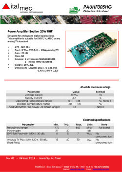
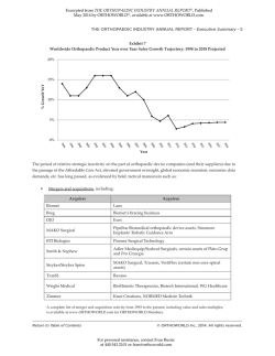
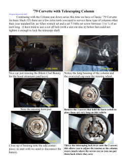
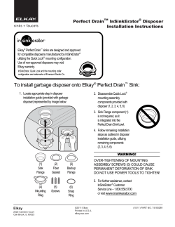
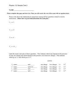
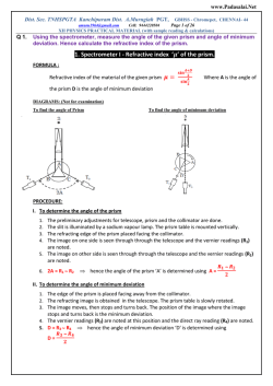
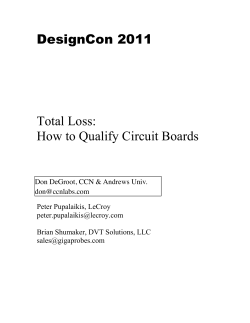
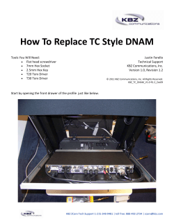
Authors Frank1471 and Chrizy_D.uk KEF PSW – How to replace C52. (rev. 17th March 2012) Applies to Kef models: PSW2000, 2010, 2500, Celestion S10 Note: Kef PSW1000 and Celestion S8. C52 is actually C58 and C55-56 are C52 and C53. Background. Anyone who owns one of the models above will experience this fault. Kef, in their infinite wisdom committed a minor design flaw in positioning a small capacitor (C52) very close to some very hot resistors on the power amplifier board. High temperatures drastically shorten the life of such capacitors by causing the semi-liquid electrolyte to dry-out. This causes the relay to buzz. ● If this is the only problem with your PSW, then read-on. Automatic on-off switching. There is a universal misunderstanding of what this function actually does. The automatic on-off switching does nothing more than mute the speaker. There is absolutely no power saving accomplished by this function. Many owners leave their sub-woofer powered continuously in the belief that, because the light has changed from green to red, their sub-woofer has powered off. This is not the case. The internal electronics are still consuming the same power and shortening the life of C52 and other capacitors. C52 forms part of the loudspeaker protection circuitry. In technical terms, it smooths the half-wave rectified supply that powers the relay (RLY1) coil. Its value (47uF) has been chosen so that the relay dropsout quickly when the power is removed. This is to avoid an objectionable loudspeaker thump as the amplifier powers down. As C52 ages rapidly due to over-heating, its value slowly reduces to to the point at which its smoothing effect is insufficient. This causes the mechanical buzzing noise which is indicative of this common fault. Fortunately, C52 can be easily replaced by a competent DIY audio enthusiast but the work does involve some dismantling and soldering on the power amplifier PCB. Two other small capacitors (C55, C56) should also be replaced as they will, without doubt fail next. Resistors R148, R149 can also be removed to reduce the heat in this area. These play no part in the operation of the amplifier and merely discharge the main smoothing capacitors after switch-off. What is needed: •Fine soldering iron and solder plus the experience to use it. •Solder-sucker or de-solder braid. •Pozi No1 screwdriver. •Small flat-blade screwdriver. •Toilet paper. (The factory applies copious amounts of heat-sink paste to the power output transistors. This will get on your hands, tools etc. and can get a bit messy unless you are careful. The quantity applied is excessive. Only a very thin layer is required for best heat transfer). Components: 1x 47uF 63v 105°C Radial (47uF 100v 105°C Radial also suitable) 2x 220uF 25v 105°C Radial PSW2000 and PSW2010 differences: CN3 not fitted to PSW2000 Some models of PSW2000 have a capacitor soldered to a lug on one PCB mounting screw. The same screw has a fibre washer beneath the PCB. (this usually stays put but needs to be in place) This document is licensed under a Creative Commons Attribution 3.0 License Page 1 - 8 Remove the 8x screws (highlighted) from the perimeter of the amplifier. Carefully free the amplifier from the cabinet. Note, there is a rubber seal between the amplifier cabinet. Sometimes it is necessary to “crack” this seal by prising one corner with a flat blade screwdriver. If you do this, be careful not to mark the cabinet. Once the seal is broken, carefully lift the amplifier out and pull off the two speaker connectors from the circuit board. Take care here as the wire is short and the connectors are tight. The speaker connectors are flat-blade type and benefit from a slight side-to-side wiggle as you pull them off. The loudspeaker wires are colour coded and marked + and – on the board so do not worry about refitting them at this stage. (Red +, Black -) Please note: The two PCB's have what look like miniature plug and sockets for the interconnecting cables. Apart from CN3, these are not connectors and cannot be removed without de-soldering. Fortunately. We don't need to remove any of these for this simple repair. Removal of the amplifier heat-sink from the front plate. Find a small tray or similar to put the screws in. Some of the screws will have white, heat-sink compound on them which can get a bit messy. One reason for having the toilet paper. Cut the cable tie and remove the 3x push-on connectors from the transformer. Note where the black wire comes from. AC1 and AC2 are interchangeable but the black wire is critical. Remove connector CN3 by gently pulling. (not fitted on PSW2000) This document is licensed under a Creative Commons Attribution 3.0 License Page 2 - 8 Remove the 4x screws from the front panel securing the heat-sink. Gently prise the heat-sink free from the front panel using the flat-blade screwdriver under one corner. Pull-off three pieces of toilet paper, each two sheets long. Remove the 4x PCB mounting screws. There is an insulating plate underneath, between the heat-sink and the front panel. This is redundant and impedes the transfer of heat. This will be removed later. There is one variation that you might encounter at this stage. ● R143, R144, Q11 and Q13 are extended on wires and mounted on the heat-sink. (Kef's latest revision) 1. Prise off the insulator board and discard. Do not put this back on re-assembly. The under-side will be coated with white heat-sink paste. Take your two pieces of toilet paper and stick one to the bottom of the heat-sink and another to the front panel so that it covers the sticky mess while you work on it. 2. If applicable, unscrew the clamp holding R143, R144 to the rear of the heat-sink. They are covered in heat-sink paste so I normally pop then into a small poly-bag to stop the paste going everywhere. Unscrew the clamp holding Q11, Q13 to the centre of the heat-sink. Gently release Q11, Q13 from the heat-sink. Cover the heat-sink paste as in (2). •Take care to note which clamp goes where as the screws are different. Rest the heat-sink at an angle and remove the 4x power transistor mounting screws. These will be covered in white heat-sink paste, hence the small tray for screws. Using the flat-blade screwdriver, gently free the 4x power transistors from the heat-sink paste. Note, there are fragile, insulating (mica) washers under each transistor. They will either stick to the transistors or the heat-sink. Try not to disturb their positioning as the holes must line-up for re-assembly. Hold the PCB by its edges and carefully free it from the heat-sink. Lift the amplifier board over the top of the pre-amp board, on its wires so that the track side is uppermost. This document is licensed under a Creative Commons Attribution 3.0 License Page 3 - 8 The 4x power transistors will be covered in heat-sink paste so use another piece of toilet paper to cover these while you work on it. Take extra care when de-soldering components. It is very easy to “lift” and damage the fragile tracks on boards that have been overheated for many years. Replace C52 but stand it off the board by 15mm or so using silicone sleeving. (C52 stand-off modification) – Double check polarity!!! Remove R148-149 C52 stand-off modification C55, C56 near the 15v regulators This document is licensed under a Creative Commons Attribution 3.0 License Page 4 - 8 Two other capacitors that are absolutely critical and suffer from poor design are C55, C56 near the +/-15v regulators. You should replace these at the same time. Take care to replace all capacitors with the correct polarity or the results will be disastrous. See Appendix. Re-assembly. Check that the output transistor mica washers are still in place and the holes are aligned. If not gently slide the mica washers into the correct place. Place the amplifier board in position on the heat sink and replace the 4 PCB mounting screws. Leave these very loose at the moment. Replace the power transistor mounting screws and tighten firmly but do not over tighten. Tighten the 4x PCB screws. (the holes in the PCB are slotted so that undue stress is not placed upon the output transistor leads) If applicable, replace Q11, Q13 under their clamp being careful to replace their insulating pads. Q11 & Q13 do not need any heat-sink paste so clean around the area for a neater result. Remove any protective paper and locate the heat sink flat onto the front panel. There should be a small amount of heat-sink compound between the two surfaces. If you haven't disturbed this too much, there will still be plenty left. With the assembly, face down, insert the 4x self tapping screws from underneath. Note: Only one or two of the four screws have shake-proof washers. If applicable, replace R143 and R144 under their clamps. Be careful not to over-tighten the clamp securing R143, R144 as the ceramic resistors are not intended to be clamped this way and can crack. These do need heat-sink compound. Replace the transformer connectors being careful to get the black wire on the common terminal.(this is labelled as 0V). This document is licensed under a Creative Commons Attribution 3.0 License Page 5 - 8 Testing. Warning: There are exposed, live mains terminals on the voltage selector board. Check everything again and if you are happy, ensure the “Auto/Manual” is switched to Manual, apply power and switch-on. If all is well, you she be rewarded by a click as relay RLY1 operates which indicates that all is well. If you have a multimeter, check the output DC offset voltage across the speaker terminals. This should be <0.1v and can be +ve or -ve. Re-connect the loudspeaker leads (Red +, Black -) and fix the amplifier into the cabinet with the 8x screws. These need to be tight to stop rattles but do not over-tighten as MDF is basically thick cardboard! After this work the same fault should not re-occur. If things go wrong: If RLY1 fails to operate when the LED is green, this indicates that there is an amplifier fault. Check the output DC offset voltage and see the fault finding guide. If the fuse blows: Check the transformer push-on connections. Check that the power transistor mica washers are correctly in place and undamaged. Revisions. I am always happy to revise this document with the help of your comments. 28th September 2010 FDJ 30th October 2010 FDJ 12th November 2020 FDJ 5th January 2011 FDJ 17th March 2012 FDJ 1 July 2014 Removal of R148-149 This document is licensed under a Creative Commons Attribution 3.0 License Page 6 - 8 Appendix – Identification of components. PSW2000 and PSW2010 amplifier board PSW2010 amplifier board with Kef's latest revision modifications Q11, Q13, R143, R144 have been extended on wires and fixed to the heat-sink. Messy but a big improvement in reliability! This document is licensed under a Creative Commons Attribution 3.0 License Page 7 - 8 Capacitor polarity. It is absolutely vital that the electrolytic capacitors are installed with the correct polarity. C52 WILL EXPLODE if installed with reverse polarity. Capacitors are quite well marked for polarity. The “-” side is marked with a stripe, sometimes showing the minus (-) symbol. In addition, the “+” lead is longer. - + + The PCB capacitor positions are clearly marked with a circle. The shaded half indicating the “-” connection. + + This document is licensed under a Creative Commons Attribution 3.0 License Page 8 - 8
© Copyright 2026 Paperzz