APPLICATION NOTE
AT03256: SAM D20/D21 Serial USART Driver
(SERCOM USART)
ASF PROGRAMMERS MANUAL
SAM D20/D21 Serial USART Driver (SERCOM USART)
This driver for SAM D20/D21 devices provides an interface for the configuration
and management of the SERCOM module in its USART mode to transfer or receive
USART data frames. The following driver API modes are covered by this manual:
в—Џ
Polled APIs
в—Џ
Callback APIs
The following peripherals are used by this module:
в—Џ
SERCOM (Serial Communication Interface)
The outline of this documentation is as follows:
в—Џ
Prerequisites
в—Џ
Module Overview
в—Џ
Special Considerations
в—Џ
Extra Information
в—Џ
Examples
в—Џ
API Overview
42118D-SAMD20/D21-02/2014
Table of Contents
SAM D20/D21 Serial USART Driver (SERCOM USART) .................. 1
Software License ................................................................................ 4
1. Prerequisites ................................................................................. 5
2. Module Overview .......................................................................... 6
2.1.
2.2.
2.3.
2.4.
2.5.
2.6.
Driver Feature Macro Definition .....................................................
Frame Format ............................................................................
Synchronous mode .....................................................................
2.3.1.
Data sampling ................................................................
Asynchronous mode ....................................................................
2.4.1.
Transmitter/receiver clock matching ....................................
Parity ........................................................................................
GPIO configuration ......................................................................
6
6
6
7
7
7
7
7
3. Special Considerations ................................................................. 8
4. Extra Information .......................................................................... 9
5. Examples .................................................................................... 10
6. API Overview .............................................................................. 11
6.1.
6.2.
6.3.
6.4.
6.5.
Variable and Type Definitions ...................................................... 11
6.1.1.
Type usart_callback_t ................................................... 11
Structure Definitions ................................................................... 11
6.2.1.
Struct usart_config ........................................................ 11
6.2.2.
Struct usart_module ....................................................... 12
Macro Definitions ...................................................................... 12
6.3.1.
Driver feature definition .................................................. 12
6.3.2.
Macro PINMUX_DEFAULT ............................................. 13
6.3.3.
Macro PINMUX_UNUSED ............................................. 13
6.3.4.
Macro USART_TIMEOUT .............................................. 14
Function Definitions ................................................................... 14
6.4.1.
Lock/Unlock ................................................................. 14
6.4.2.
Writing and reading ....................................................... 14
6.4.3.
Enabling/Disabling receiver and transmitter ........................ 17
6.4.4.
Callback Management .................................................... 18
6.4.5.
Writing and reading ....................................................... 19
6.4.6.
Function usart_disable() ................................................ 23
6.4.7.
Function usart_enable() ................................................. 23
6.4.8.
Function usart_get_config_defaults() ................................ 23
6.4.9.
Function usart_init() ...................................................... 24
6.4.10. Function usart_is_syncing() ............................................ 25
6.4.11. Function usart_reset() ................................................... 25
Enumeration Definitions .............................................................. 25
6.5.1.
Enum usart_callback .................................................... 25
6.5.2.
Enum usart_character_size ............................................ 26
6.5.3.
Enum usart_dataorder .................................................. 26
6.5.4.
Enum usart_parity ........................................................ 26
6.5.5.
Enum usart_sample_adjustment ..................................... 27
6.5.6.
Enum usart_sample_rate ............................................... 27
6.5.7.
Enum usart_signal_mux_settings .................................... 27
6.5.8.
Enum usart_stopbits ..................................................... 28
6.5.9.
Enum usart_transceiver_type ......................................... 28
6.5.10. Enum usart_transfer_mode ............................................ 28
7. Extra Information for SERCOM USART Driver .......................... 29
AT03256: SAM D20/D21 Serial USART Driver (SERCOM USART) [APPLICATION NOTE]
42118D-SAMD20/D21-02/2014
2
7.1.
7.2.
7.3.
7.4.
Acronyms ................................................................................
Dependencies ...........................................................................
Errata ......................................................................................
Module History .........................................................................
29
29
29
29
8. Examples for SERCOM USART Driver ...................................... 31
8.1.
8.2.
8.3.
Quick Start Guide for SERCOM USART - Basic ..............................
8.1.1.
Setup ..........................................................................
8.1.2.
Use Case ....................................................................
Quick Start Guide for SERCOM USART - Callback ..........................
8.2.1.
Setup ..........................................................................
8.2.2.
Use Case ....................................................................
Quick Start Guide for Using DMA with SERCOM USART ..................
8.3.1.
Setup ..........................................................................
8.3.2.
Use Case ....................................................................
31
31
32
33
33
36
36
37
42
9. SERCOM USART MUX Settings ............................................... 44
Index ................................................................................................. 45
Document Revision History .............................................................. 46
AT03256: SAM D20/D21 Serial USART Driver (SERCOM USART) [APPLICATION NOTE]
42118D-SAMD20/D21-02/2014
3
Software License
Redistribution and use in source and binary forms, with or without modification, are permitted provided that the
following conditions are met:
1. Redistributions of source code must retain the above copyright notice, this list of conditions and the following
disclaimer.
2. Redistributions in binary form must reproduce the above copyright notice, this list of conditions and the following
disclaimer in the documentation and/or other materials provided with the distribution.
3. The name of Atmel may not be used to endorse or promote products derived from this software without specific
prior written permission.
4. This software may only be redistributed and used in connection with an Atmel microcontroller product.
THIS SOFTWARE IS PROVIDED BY ATMEL "AS IS" AND ANY EXPRESS OR IMPLIED WARRANTIES,
INCLUDING, BUT NOT LIMITED TO, THE IMPLIED WARRANTIES OF MERCHANTABILITY, FITNESS FOR A
PARTICULAR PURPOSE AND NON-INFRINGEMENT ARE EXPRESSLY AND SPECIFICALLY DISCLAIMED. IN
NO EVENT SHALL ATMEL BE LIABLE FOR ANY DIRECT, INDIRECT, INCIDENTAL, SPECIAL, EXEMPLARY,
OR CONSEQUENTIAL DAMAGES (INCLUDING, BUT NOT LIMITED TO, PROCUREMENT OF SUBSTITUTE
GOODS OR SERVICES; LOSS OF USE, DATA, OR PROFITS; OR BUSINESS INTERRUPTION) HOWEVER
CAUSED AND ON ANY THEORY OF LIABILITY, WHETHER IN CONTRACT, STRICT LIABILITY, OR TORT
(INCLUDING NEGLIGENCE OR OTHERWISE) ARISING IN ANY WAY OUT OF THE USE OF THIS SOFTWARE,
EVEN IF ADVISED OF THE POSSIBILITY OF SUCH DAMAGE.
AT03256: SAM D20/D21 Serial USART Driver (SERCOM USART) [APPLICATION NOTE]
42118D-SAMD20/D21-02/2014
4
1.
Prerequisites
To use the USART you need to have a GCLK generator enabled and running that can be used as the SERCOM
clock source. This can either be configured in conf_clocks.h or by using the system clock driver.
AT03256: SAM D20/D21 Serial USART Driver (SERCOM USART) [APPLICATION NOTE]
42118D-SAMD20/D21-02/2014
5
2.
Module Overview
This driver will use one (or more) SERCOM interfaces on the system and configure it to run as a USART interface
in either synchronous or asynchronous mode.
2.1
Driver Feature Macro Definition
Driver Feature Macro
Supported devices
FEATURE_USART_SYNC_SCHEME_V2
SAMD21
FEATURE_USART_OVER_SAMPLE
SAMD21
FEATURE_USART_HARDWARE_FLOW_CONTROL
SAMD21
FEATURE_USART_IRDA
SAMD21
FEATURE_USART_LIN_SLAVE
SAMD21
FEATURE_USART_COLLISION_DECTION
SAMD21
FEATURE_USART_START_FRAME_DECTION
SAMD21
FEATURE_USART_IMMEDIATE_BUFFER_OVERFLOW_NOTIFICATION
SAMD21
Note
2.2
The specific features are only available in the driver when the selected device supports those
features.
Frame Format
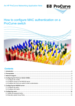
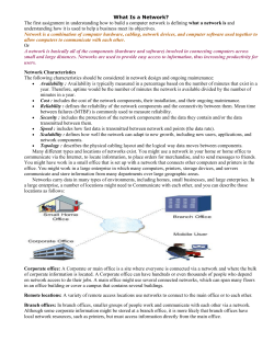
Communication is based on frames, where the frame format can be customized to accommodate a wide range of
standards. A frame consists of a start bit, a number of data bits, an optional parity bit for error detection as well as a
configurable length stop bit(s) - see Figure 2-1: USART Frame overview on page 6. Table 2-1: USART Frame
Parameters on page 6 shows the available parameters you can change in a frame.
Table 2-1. USART Frame Parameters
Parameter
Options
Start bit
1
Data bits
5, 6, 7, 8, 9
Parity bit
None, Even, Odd
Stop bits
1, 2
Figure 2-1. USART Frame overview
Frame
(IDLE)
2.3
St
0
1
2
3
4
[5]
[6]
[7]
[8]
[P]
Sp1
[Sp2]
(St/IDLE)
Synchronous mode
In synchronous mode a dedicated clock line is provided; either by the USART itself if in master mode, or by an
external master if in slave mode. Maximum transmission speed is the same as the GCLK clocking the USART
peripheral when in slave mode, and the GCLK divided by two if in master mode. In synchronous mode the interface
needs three lines to communicate:
в—Џ
TX (Transmit pin)
в—Џ
RX (Receive pin)
AT03256: SAM D20/D21 Serial USART Driver (SERCOM USART) [APPLICATION NOTE]
42118D-SAMD20/D21-02/2014
6
в—Џ
2.3.1
XCK (Clock pin)
Data sampling
In synchronous mode the data is sampled on either the rising or falling edge of the clock signal. This is configured
by setting the clock polarity in the configuration struct.
2.4
Asynchronous mode
In asynchronous mode no dedicated clock line is used, and the communication is based on matching the clock
speed on the transmitter and receiver. The clock is generated from the internal SERCOM baudrate generator, and
the frames are synchronized by using the frame start bits. Maximum transmission speed is limited to the SERCOM
GCLK divided by 16. In asynchronous mode the interface only needs two lines to communicate:
2.4.1
в—Џ
TX (Transmit pin)
в—Џ
RX (Receive pin)
Transmitter/receiver clock matching
For successful transmit and receive using the asynchronous mode the receiver and transmitter clocks needs to be
closely matched. When receiving a frame that does not match the selected baud rate closely enough the receiver
will be unable to synchronize the frame(s), and garbage transmissions will result.
2.5
Parity
Parity can be enabled to detect if a transmission was in error. This is done by counting the number of "1" bits in the
frame. When using Even parity the parity bit will be set if the total number of "1"s in the frame are an even number.
If using Odd parity the parity bit will be set if the total number of "1"s are Odd.
When receiving a character the receiver will count the number of "1"s in the frame and give an error if the received
frame and parity bit disagree.
2.6
GPIO configuration
The SERCOM module has four internal pads; the RX pin can be placed freely on any one of the four pads, and the
TX and XCK pins have two predefined positions that can be selected as a pair. The pads can then be routed to an
external GPIO pin using the normal pin multiplexing scheme on the SAM D20/D21.
AT03256: SAM D20/D21 Serial USART Driver (SERCOM USART) [APPLICATION NOTE]
42118D-SAMD20/D21-02/2014
7
3.
Special Considerations
Never execute large portions of code in the callbacks. These are run from the interrupt routine, and thus having
long callbacks will keep the processor in the interrupt handler for an equally long time. A common way to handle
this is to use global flags signaling the main application that an interrupt event has happened, and only do the
minimal needed processing in the callback.
AT03256: SAM D20/D21 Serial USART Driver (SERCOM USART) [APPLICATION NOTE]
42118D-SAMD20/D21-02/2014
8
4.
Extra Information
For extra information see Extra Information for SERCOM USART Driver. This includes:
в—Џ
Acronyms
в—Џ
Dependencies
в—Џ
Errata
в—Џ
Module History
AT03256: SAM D20/D21 Serial USART Driver (SERCOM USART) [APPLICATION NOTE]
42118D-SAMD20/D21-02/2014
9
5.
Examples
For a list of examples related to this driver, see Examples for SERCOM USART Driver.
AT03256: SAM D20/D21 Serial USART Driver (SERCOM USART) [APPLICATION NOTE]
42118D-SAMD20/D21-02/2014
10
6.
API Overview
6.1
Variable and Type Definitions
6.1.1
Type usart_callback_t
typedef void(* usart_callback_t )(const struct usart_module *const module)
Type of the callback functions
6.2
Structure Definitions
6.2.1
Struct usart_config
Configuration options for USART
Table 6-1. Members
Type
Name
Description
uint32_t
baudrate
USART baud rate
enum usart_character_size
character_size
USART character size
bool
clock_polarity_inverted
USART Clock Polarity. If true, data
changes on falling XCK edge and
is sampled at rising edge. If false,
data changes on rising XCK edge
and is sampled at falling edge.
bool
collision_detection_enable
Enable collision dection
enum usart_dataorder
data_order
USART bit order (MSB or LSB first)
bool
encoding_format_enable
Enable IrDA encoding format
uint32_t
ext_clock_freq
External clock frequency in
synchronous mode. This must be
set if use_external_clock is true.
enum gclk_generator
generator_source
GCLK generator source
bool
immediate_buffer_overflow_notificationControls when the buffer overflow
status bit is asserted when a buffer
overflow occurs.
bool
lin_slave_enable
Enable LIN Slave Support
enum usart_signal_mux_settings
mux_setting
USART pin out
enum usart_parity
parity
USART parity
uint32_t
pinmux_pad0
PAD0 pinmux
uint32_t
pinmux_pad1
PAD1 pinmux
uint32_t
pinmux_pad2
PAD2 pinmux
uint32_t
pinmux_pad3
PAD3 pinmux
uint8_t
receive_pulse_length
The minimum pulse length that is
required for a pulse to be accepted
by the IrDA receiver
bool
receiver_enable
Enable receiver
bool
run_in_standby
If true the USART will be kept
running in Standby sleep mode
AT03256: SAM D20/D21 Serial USART Driver (SERCOM USART) [APPLICATION NOTE]
42118D-SAMD20/D21-02/2014
11
6.2.2
Type
Name
Description
enum usart_sample_adjustment
sample_adjustment
USART sample adjustment
enum usart_sample_rate
sample_rate
USART sample rate
bool
start_frame_detection_enable
Enable start of frame dection
enum usart_stopbits
stopbits
Number of stop bits
enum usart_transfer_mode
transfer_mode
USART in asynchronous or
synchronous mode
bool
transmitter_enable
Enable transmitter
bool
use_external_clock
States whether to use the external
clock applied to the XCK pin.
In synchronous mode the shift
register will act directly on the XCK
clock. In asynchronous mode the
XCK will be the input to the USART
hardware module.
Struct usart_module
SERCOM USART driver software instance structure, used to retain software state information of an associated
hardware module instance.
Note
The fields of this structure should not be altered by the user application; they are reserved for moduleinternal use only.
6.3
Macro Definitions
6.3.1
Driver feature definition
Define SERCOM USART features set according to different device family.
6.3.1.1
Macro FEATURE_USART_SYNC_SCHEME_V2
#define FEATURE_USART_SYNC_SCHEME_V2
Usart sync scheme version 2.
6.3.1.2
Macro FEATURE_USART_OVER_SAMPLE
#define FEATURE_USART_OVER_SAMPLE
Usart over sampling.
6.3.1.3
Macro FEATURE_USART_HARDWARE_FLOW_CONTROL
#define FEATURE_USART_HARDWARE_FLOW_CONTROL
Usart hardware control flow.
AT03256: SAM D20/D21 Serial USART Driver (SERCOM USART) [APPLICATION NOTE]
42118D-SAMD20/D21-02/2014
12
6.3.1.4
Macro FEATURE_USART_IRDA
#define FEATURE_USART_IRDA
IrDA mode.
6.3.1.5
Macro FEATURE_USART_LIN_SLAVE
#define FEATURE_USART_LIN_SLAVE
LIN slave mode.
6.3.1.6
Macro FEATURE_USART_COLLISION_DECTION
#define FEATURE_USART_COLLISION_DECTION
Usart collision detection.
6.3.1.7
Macro FEATURE_USART_START_FRAME_DECTION
#define FEATURE_USART_START_FRAME_DECTION
Usart start frame detection.
6.3.1.8
Macro FEATURE_USART_IMMEDIATE_BUFFER_OVERFLOW_NOTIFICATION
#define FEATURE_USART_IMMEDIATE_BUFFER_OVERFLOW_NOTIFICATION
Usart start buffer overflow notification.
6.3.2
Macro PINMUX_DEFAULT
#define PINMUX_DEFAULT 0
Default pin mux.
6.3.3
Macro PINMUX_UNUSED
#define PINMUX_UNUSED 0xFFFFFFFF
Unused PIN mux.
AT03256: SAM D20/D21 Serial USART Driver (SERCOM USART) [APPLICATION NOTE]
42118D-SAMD20/D21-02/2014
13
6.3.4
Macro USART_TIMEOUT
#define USART_TIMEOUT 0xFFFF
USART timeout value.
6.4
Function Definitions
6.4.1
Lock/Unlock
6.4.1.1
Function usart_lock()
Attempt to get lock on driver instance.
enum status_code usart_lock(
struct usart_module *const module)
This function checks the instance's lock, which indicates whether or not it is currently in use, and sets the lock if it
was not already set.
The purpose of this is to enable exclusive access to driver instances, so that, e.g., transactions by different services
will not interfere with each other.
Table 6-2. Parameters
Data direction
Parameter name
Description
[in, out]
module
Pointer to the driver instance to
lock.
Table 6-3. Return Values
6.4.1.2
Return value
Description
STATUS_OK
if the module was locked.
STATUS_BUSY
if the module was already locked.
Function usart_unlock()
Unlock driver instance.
void usart_unlock(
struct usart_module *const module)
This function clears the instance lock, indicating that it is available for use.
Table 6-4. Parameters
Data direction
Parameter name
Description
[in, out]
module
Pointer to the driver instance to
lock.
6.4.2
Writing and reading
6.4.2.1
Function usart_write_wait()
AT03256: SAM D20/D21 Serial USART Driver (SERCOM USART) [APPLICATION NOTE]
42118D-SAMD20/D21-02/2014
14
Transmit a character via the USART.
enum status_code usart_write_wait(
struct usart_module *const module,
const uint16_t tx_data)
This blocking function will transmit a single character via the USART.
Table 6-5. Parameters
Data direction
Parameter name
Description
[in]
module
Pointer to the software instance
struct
[in]
tx_data
Data to transfer
Returns
Status of the operation
Table 6-6. Return Values
6.4.2.2
Return value
Description
STATUS_OK
If the operation was completed
STATUS_BUSY
If the operation was not completed, due to the USART
module being busy.
STATUS_ERR_DENIED
If the transmitter is not enabled
Function usart_read_wait()
Receive a character via the USART.
enum status_code usart_read_wait(
struct usart_module *const module,
uint16_t *const rx_data)
This blocking function will receive a character via the USART.
Table 6-7. Parameters
Returns
Data direction
Parameter name
Description
[in]
module
Pointer to the software instance
struct
[out]
rx_data
Pointer to received data
Status of the operation
Table 6-8. Return Values
Return value
Description
STATUS_OK
If the operation was completed
STATUS_BUSY
If the operation was not completed, due to the USART
module being busy
AT03256: SAM D20/D21 Serial USART Driver (SERCOM USART) [APPLICATION NOTE]
42118D-SAMD20/D21-02/2014
15
6.4.2.3
Return value
Description
STATUS_ERR_BAD_FORMAT
If the operation was not completed, due to
configuration mismatch between USART and the
sender
STATUS_ERR_BAD_OVERFLOW
If the operation was not completed, due to the baud
rate being too low or the system frequency being too
high
STATUS_ERR_BAD_DATA
If the operation was not completed, due to data being
corrupted
STATUS_ERR_DENIED
If the receiver is not enabled
Function usart_write_buffer_wait()
Transmit a buffer of characters via the USART.
enum status_code usart_write_buffer_wait(
struct usart_module *const module,
const uint8_t * tx_data,
uint16_t length)
This blocking function will transmit a block of length characters via the USART
Note
Using this function in combination with the interrupt (_job) functions is not recommended as it has no
functionality to check if there is an ongoing interrupt driven operation running or not.
Table 6-9. Parameters
Returns
Data direction
Parameter name
Description
[in]
module
Pointer to USART software
instance struct
[in]
tx_data
Pointer to data to transmit
[in]
length
Number of characters to transmit
Status of the operation
Table 6-10. Return Values
6.4.2.4
Return value
Description
STATUS_OK
If operation was completed
STATUS_ERR_INVALID_ARG
If operation was not completed, due to invalid
arguments
STATUS_ERR_TIMEOUT
If operation was not completed, due to USART module
timing out
STATUS_ERR_DENIED
If the transmitter is not enabled
Function usart_read_buffer_wait()
Receive a buffer of length characters via the USART.
AT03256: SAM D20/D21 Serial USART Driver (SERCOM USART) [APPLICATION NOTE]
42118D-SAMD20/D21-02/2014
16
enum status_code usart_read_buffer_wait(
struct usart_module *const module,
uint8_t * rx_data,
uint16_t length)
This blocking function will receive a block of length characters via the USART.
Note
Using this function in combination with the interrupt (*_job) functions is not recommended as it has
no functionality to check if there is an ongoing interrupt driven operation running or not.
Table 6-11. Parameters
Returns
Data direction
Parameter name
Description
[in]
module
Pointer to USART software
instance struct
[out]
rx_data
Pointer to receive buffer
[in]
length
Number of characters to receive
Status of the operation.
Table 6-12. Return Values
Return value
Description
STATUS_OK
If operation was completed
STATUS_ERR_INVALID_ARG
If operation was not completed, due to an invalid
argument being supplied
STATUS_ERR_TIMEOUT
If operation was not completed, due to USART module
timing out
STATUS_ERR_BAD_FORMAT
If the operation was not completed, due to a
configuration mismatch between USART and the
sender
STATUS_ERR_BAD_OVERFLOW
If the operation was not completed, due to the baud
rate being too low or the system frequency being too
high
STATUS_ERR_BAD_DATA
If the operation was not completed, due to data being
corrupted
STATUS_ERR_DENIED
If the receiver is not enabled
6.4.3
Enabling/Disabling receiver and transmitter
6.4.3.1
Function usart_enable_transceiver()
Enable Transceiver.
void usart_enable_transceiver(
struct usart_module *const module,
enum usart_transceiver_type transceiver_type)
Enable the given transceiver. Either RX or TX.
AT03256: SAM D20/D21 Serial USART Driver (SERCOM USART) [APPLICATION NOTE]
42118D-SAMD20/D21-02/2014
17
Table 6-13. Parameters
6.4.3.2
Data direction
Parameter name
Description
[in]
module
Pointer to USART software
instance struct
[in]
transceiver_type
Transceiver type.
Function usart_disable_transceiver()
Disable Transceiver.
void usart_disable_transceiver(
struct usart_module *const module,
enum usart_transceiver_type transceiver_type)
Disable the given transceiver (RX or TX).
Table 6-14. Parameters
Data direction
Parameter name
Description
[in]
module
Pointer to USART software
instance struct
[in]
transceiver_type
Transceiver type.
6.4.4
Callback Management
6.4.4.1
Function usart_register_callback()
Registers a callback.
void usart_register_callback(
struct usart_module *const module,
usart_callback_t callback_func,
enum usart_callback callback_type)
Registers a callback function which is implemented by the user.
Note
The callback must be enabled by usart_enable_callback, in order for the interrupt handler to call it
when the conditions for the callback type are met.
Table 6-15. Parameters
6.4.4.2
Data direction
Parameter name
Description
[in]
module
Pointer to USART software
instance struct
[in]
callback_func
Pointer to callback function
[in]
callback_type
Callback type given by an enum
Function usart_unregister_callback()
Unregisters a callback.
AT03256: SAM D20/D21 Serial USART Driver (SERCOM USART) [APPLICATION NOTE]
42118D-SAMD20/D21-02/2014
18
void usart_unregister_callback(
struct usart_module * module,
enum usart_callback callback_type)
Unregisters a callback function which is implemented by the user.
Table 6-16. Parameters
6.4.4.3
Data direction
Parameter name
Description
[in, out]
module
Pointer to USART software
instance struct
[in]
callback_type
Callback type given by an enum
Function usart_enable_callback()
Enables callback.
void usart_enable_callback(
struct usart_module *const module,
enum usart_callback callback_type)
Enables the callback function registered by the usart_register_callback. The callback function will be called from
the interrupt handler when the conditions for the callback type are met.
Table 6-17. Parameters
6.4.4.4
Data direction
Parameter name
Description
[in]
module
Pointer to USART software
instance struct
[in]
callback_type
Callback type given by an enum
Function usart_disable_callback()
Disable callback.
void usart_disable_callback(
struct usart_module *const module,
enum usart_callback callback_type)
Disables the callback function registered by the usart_register_callback, and the callback will not be called from the
interrupt routine.
Table 6-18. Parameters
Data direction
Parameter name
Description
[in]
module
Pointer to USART software
instance struct
[in]
callback_type
Callback type given by an enum
6.4.5
Writing and reading
6.4.5.1
Function usart_write_job()
AT03256: SAM D20/D21 Serial USART Driver (SERCOM USART) [APPLICATION NOTE]
42118D-SAMD20/D21-02/2014
19
Asynchronous write a single char.
enum status_code usart_write_job(
struct usart_module *const module,
const uint16_t tx_data)
Sets up the driver to write the data given. If registered and enabled, a callback function will be called when the
transmit is completed.
Table 6-19. Parameters
Data direction
Parameter name
Description
[in]
module
Pointer to USART software
instance struct
[in]
tx_data
Data to transfer
Returns
Status of the operation
Table 6-20. Return Values
6.4.5.2
Return value
Description
STATUS_OK
If operation was completed
STATUS_BUSY
If operation was not completed, due to the USART
module being busy
STATUS_ERR_DENIED
If the transmitter is not enabled
Function usart_read_job()
Asynchronous read a single char.
enum status_code usart_read_job(
struct usart_module *const module,
uint16_t *const rx_data)
Sets up the driver to read data from the USART module to the data pointer given. If registered and enabled, a
callback will be called when the receiving is completed.
Table 6-21. Parameters
Returns
Data direction
Parameter name
Description
[in]
module
Pointer to USART software
instance struct
[out]
rx_data
Pointer to where received data
should be put
Status of the operation
Table 6-22. Return Values
Return value
Description
STATUS_OK
If operation was completed
AT03256: SAM D20/D21 Serial USART Driver (SERCOM USART) [APPLICATION NOTE]
42118D-SAMD20/D21-02/2014
20
6.4.5.3
Return value
Description
STATUS_BUSY
If operation was not completed,
Function usart_write_buffer_job()
Asynchronous buffer write.
enum status_code usart_write_buffer_job(
struct usart_module *const module,
uint8_t * tx_data,
uint16_t length)
Sets up the driver to write a given buffer over the USART. If registered and enabled, a callback function will be
called.
Table 6-23. Parameters
Data direction
Parameter name
Description
[in]
module
Pointer to USART software
instance struct
[in]
tx_data
Pointer do data buffer to transmit
[in]
length
Length of the data to transmit
Returns
Status of the operation
Table 6-24. Return Values
6.4.5.4
Return value
Description
STATUS_OK
If operation was completed successfully.
STATUS_BUSY
If operation was not completed, due to the USART
module being busy
STATUS_ERR_INVALID_ARG
If operation was not completed, due to invalid
arguments
STATUS_ERR_DENIED
If the transmitter is not enabled
Function usart_read_buffer_job()
Asynchronous buffer read.
enum status_code usart_read_buffer_job(
struct usart_module *const module,
uint8_t * rx_data,
uint16_t length)
Sets up the driver to read from the USART to a given buffer. If registered and enabled, a callback function will be
called.
Table 6-25. Parameters
Data direction
Parameter name
Description
[in]
module
Pointer to USART software
instance struct
AT03256: SAM D20/D21 Serial USART Driver (SERCOM USART) [APPLICATION NOTE]
42118D-SAMD20/D21-02/2014
21
Data direction
Parameter name
Description
[out]
rx_data
Pointer to data buffer to receive
[in]
length
Data buffer length
Returns
Status of the operation
Table 6-26. Return Values
6.4.5.5
Return value
Description
STATUS_OK
If operation was completed
STATUS_BUSY
If operation was not completed, due to the USART
module being busy
STATUS_ERR_INVALID_ARG
If operation was not completed, due to invalid
arguments
STATUS_ERR_DENIED
If the transmitter is not enabled
Function usart_abort_job()
Cancels ongoing read/write operation.
void usart_abort_job(
struct usart_module *const module,
enum usart_transceiver_type transceiver_type)
Cancels the ongoing read/write operation modifying parameters in the USART software struct.
Table 6-27. Parameters
6.4.5.6
Data direction
Parameter name
Description
[in]
module
Pointer to USART software
instance struct
[in]
transceiver_type
Transfer type to cancel
Function usart_get_job_status()
Get status from the ongoing or last asynchronous transfer operation.
enum status_code usart_get_job_status(
struct usart_module *const module,
enum usart_transceiver_type transceiver_type)
Returns the error from a given ongoing or last asynchronous transfer operation. Either from a read or write transfer.
Table 6-28. Parameters
Data direction
Parameter name
Description
[in]
module
Pointer to USART software
instance struct
[in]
transceiver_type
Transfer type to check
AT03256: SAM D20/D21 Serial USART Driver (SERCOM USART) [APPLICATION NOTE]
42118D-SAMD20/D21-02/2014
22
Returns
Status of the given job.
Table 6-29. Return Values
6.4.6
Return value
Description
STATUS_OK
No error occurred during the last transfer
STATUS_BUSY
A transfer is ongoing
STATUS_ERR_BAD_DATA
The last operation was aborted due to a parity error.
The transfer could be affected by external noise.
STATUS_ERR_BAD_FORMAT
The last operation was aborted due to a frame error.
STATUS_ERR_OVERFLOW
The last operation was aborted due to a buffer
overflow.
STATUS_ERR_INVALID_ARG
An invalid transceiver enum given.
Function usart_disable()
Disable module.
void usart_disable(
const struct usart_module *const module)
Disables the USART module
Table 6-30. Parameters
6.4.7
Data direction
Parameter name
Description
[in]
module
Pointer to USART software
instance struct
Function usart_enable()
Enable the module.
void usart_enable(
const struct usart_module *const module)
Enables the USART module
Table 6-31. Parameters
6.4.8
Data direction
Parameter name
Description
[in]
module
Pointer to USART software
instance struct
Function usart_get_config_defaults()
Initializes the device to predefined defaults.
void usart_get_config_defaults(
struct usart_config *const config)
AT03256: SAM D20/D21 Serial USART Driver (SERCOM USART) [APPLICATION NOTE]
42118D-SAMD20/D21-02/2014
23
Initialize the USART device to predefined defaults:
в—Џ
8-bit asynchronous USART
в—Џ
No parity
в—Џ
1 stop bit
в—Џ
9600 baud
в—Џ
Transmitter enabled
в—Џ
Receiver enabled
в—Џ
GCLK generator 0 as clock source
в—Џ
Default pin configuration
The configuration struct will be updated with the default configuration.
Table 6-32. Parameters
6.4.9
Data direction
Parameter name
Description
[in, out]
config
Pointer to configuration struct
Function usart_init()
Initializes the device.
enum status_code usart_init(
struct usart_module *const module,
Sercom *const hw,
const struct usart_config *const config)
Initializes the USART device based on the setting specified in the configuration struct.
Table 6-33. Parameters
Returns
Data direction
Parameter name
Description
[out]
module
Pointer to USART device
[in]
hw
Pointer to USART hardware
instance
[in]
config
Pointer to configuration struct
Status of the initialization
Table 6-34. Return Values
Return value
Description
STATUS_OK
The initialization was successful
STATUS_BUSY
The USART module is busy resetting
STATUS_ERR_DENIED
The USART have not been disabled in advance of
initialization
STATUS_ERR_INVALID_ARG
The configuration struct contains invalid configuration
AT03256: SAM D20/D21 Serial USART Driver (SERCOM USART) [APPLICATION NOTE]
42118D-SAMD20/D21-02/2014
24
6.4.10
Return value
Description
STATUS_ERR_ALREADY_INITIALIZED
The SERCOM instance has already been initialized
with different clock configuration
STATUS_ERR_BAUD_UNAVAILABLE
The BAUD rate given by the configuration struct
cannot be reached with the current clock configuration
Function usart_is_syncing()
Check if peripheral is busy syncing registers across clock domains.
bool usart_is_syncing(
const struct usart_module *const module)
Return peripheral synchronization status. If doing a non-blocking implementation this function can be used to check
the sync state and hold of any new actions until sync is complete. If this functions is not run; the functions will block
until the sync has completed.
Table 6-35. Parameters
Data direction
Parameter name
Description
[in]
module
Pointer to peripheral module
Returns
Peripheral sync status
Table 6-36. Return Values
6.4.11
Return value
Description
true
Peripheral is busy syncing
false
Peripheral is not busy syncing and can be read/written
without stalling the bus.
Function usart_reset()
Resets the USART module.
void usart_reset(
const struct usart_module *const module)
Disables and resets the USART module.
Table 6-37. Parameters
Data direction
Parameter name
Description
[in]
module
Pointer to the USART software
instance struct
6.5
Enumeration Definitions
6.5.1
Enum usart_callback
Callbacks for the Asynchronous USART driver
AT03256: SAM D20/D21 Serial USART Driver (SERCOM USART) [APPLICATION NOTE]
42118D-SAMD20/D21-02/2014
25
Table 6-38. Members
6.5.2
Enum value
Description
USART_CALLBACK_BUFFER_TRANSMITTED
Callback for buffer transmitted
USART_CALLBACK_BUFFER_RECEIVED
Callback for buffer received
USART_CALLBACK_ERROR
Callback for error
USART_CALLBACK_BREAK_RECEIVED
Callback for break character is received.
USART_CALLBACK_CTS_INPUT_CHANGE
Callback for a change is detected on the CTS
pin.
USART_CALLBACK_START_RECEIVED
Callback for a start condition is detected on the
RxD line.
Enum usart_character_size
Number of bits for the character sent in a frame.
Table 6-39. Members
6.5.3
Enum value
Description
USART_CHARACTER_SIZE_5BIT
The char being sent in a frame is 5 bits long
USART_CHARACTER_SIZE_6BIT
The char being sent in a frame is 6 bits long
USART_CHARACTER_SIZE_7BIT
The char being sent in a frame is 7 bits long
USART_CHARACTER_SIZE_8BIT
The char being sent in a frame is 8 bits long
USART_CHARACTER_SIZE_9BIT
The char being sent in a frame is 9 bits long
Enum usart_dataorder
The data order decides which of MSB or LSB is shifted out first when data is transferred
Table 6-40. Members
6.5.4
Enum value
Description
USART_DATAORDER_MSB
The MSB will be shifted out first during
transmission, and shifted in first during
reception
USART_DATAORDER_LSB
The LSB will be shifted out first during
transmission, and shifted in first during
reception
Enum usart_parity
Select parity USART parity mode
Table 6-41. Members
Enum value
Description
USART_PARITY_ODD
For odd parity checking, the parity bit will be set
if number of ones being transferred is even
USART_PARITY_EVEN
For even parity checking, the parity bit will be
set if number of ones being received is odd
AT03256: SAM D20/D21 Serial USART Driver (SERCOM USART) [APPLICATION NOTE]
42118D-SAMD20/D21-02/2014
26
6.5.5
Enum value
Description
USART_PARITY_NONE
No parity checking will be executed, and there
will be no parity bit in the received frame
Enum usart_sample_adjustment
The value of sample number used for majority voting
Table 6-42. Members
6.5.6
Enum value
Description
USART_SAMPLE_ADJUSTMENT_7_8_9
The first, middle and last sample number used
for majority voting is 7-8-9
USART_SAMPLE_ADJUSTMENT_9_10_11
The first, middle and last sample number used
for majority voting is 9-10-11
USART_SAMPLE_ADJUSTMENT_11_12_13
The first, middle and last sample number used
for majority voting is 11-12-13
USART_SAMPLE_ADJUSTMENT_13_14_15
The first, middle and last sample number used
for majority voting is 13-14-15
Enum usart_sample_rate
The value of sample rate and baud rate generation mode.
Table 6-43. Members
6.5.7
Enum value
Description
USART_SAMPLE_RATE_16X_ARITHMETIC
16x over-sampling using arithmetic baud rate
generation
USART_SAMPLE_RATE_16X_FRACTIONAL
16x over-sampling using fractional baud rate
generation
USART_SAMPLE_RATE_8X_ARITHMETIC
8x over-sampling using arithmetic baud rate
generation
USART_SAMPLE_RATE_8X_FRACTIONAL
8x over-sampling using fractional baud rate
generation
USART_SAMPLE_RATE_3X_ARITHMETIC
3x over-sampling using arithmetic baud rate
generation
Enum usart_signal_mux_settings
Set the functionality of the SERCOM pins.
See SERCOM USART MUX Settings for a description of the various MUX setting options.
Table 6-44. Members
Enum value
Description
USART_RX_0_TX_0_XCK_1
MUX setting RX_0_TX_0_XCK_1
USART_RX_0_TX_2_XCK_3
MUX setting RX_0_TX_2_XCK_3
USART_RX_0_TX_0_RTS_2_CTS_3
MUX setting
USART_RX_0_TX_0_RTS_2_CTS_3
AT03256: SAM D20/D21 Serial USART Driver (SERCOM USART) [APPLICATION NOTE]
42118D-SAMD20/D21-02/2014
27
6.5.8
Enum value
Description
USART_RX_1_TX_0_XCK_1
MUX setting RX_1_TX_0_XCK_1
USART_RX_1_TX_2_XCK_3
MUX setting RX_1_TX_2_XCK_3
USART_RX_1_TX_0_RTS_2_CTS_3
MUX setting
USART_RX_1_TX_0_RTS_2_CTS_3
USART_RX_2_TX_0_XCK_1
MUX setting RX_2_TX_0_XCK_1
USART_RX_2_TX_2_XCK_3
MUX setting RX_2_TX_2_XCK_3
USART_RX_2_TX_0_RTS_2_CTS_3
MUX setting
USART_RX_2_TX_0_RTS_2_CTS_3
USART_RX_3_TX_0_XCK_1
MUX setting RX_3_TX_0_XCK_1
USART_RX_3_TX_2_XCK_3
MUX setting RX_3_TX_2_XCK_3
USART_RX_3_TX_0_RTS_2_CTS_3
MUX setting
USART_RX_3_TX_0_RTS_2_CTS_3
Enum usart_stopbits
Number of stop bits for a frame.
Table 6-45. Members
6.5.9
Enum value
Description
USART_STOPBITS_1
Each transferred frame contains 1 stop bit
USART_STOPBITS_2
Each transferred frame contains 2 stop bits
Enum usart_transceiver_type
Select Receiver or Transmitter
Table 6-46. Members
6.5.10
Enum value
Description
USART_TRANSCEIVER_RX
The parameter is for the Receiver
USART_TRANSCEIVER_TX
The parameter is for the Transmitter
Enum usart_transfer_mode
Select USART transfer mode
Table 6-47. Members
Enum value
Description
USART_TRANSFER_SYNCHRONOUSLY
Transfer of data is done synchronously
USART_TRANSFER_ASYNCHRONOUSLY
Transfer of data is done asynchronously
AT03256: SAM D20/D21 Serial USART Driver (SERCOM USART) [APPLICATION NOTE]
42118D-SAMD20/D21-02/2014
28
7.
Extra Information for SERCOM USART Driver
7.1
Acronyms
Below is a table listing the acronyms used in this module, along with their intended meanings.
7.2
Acronym
Description
SERCOM
Serial Communication Interface
USART
Universal Synchronous and Asynchronous Serial
Receiver and Transmitter
LSB
Least Significant Bit
MSB
Most Significant Bit
DMA
Direct Memory Access
Dependencies
This driver has the following dependencies:
7.3
в—Џ
System Pin Multiplexer Driver
в—Џ
System clock configuration
Errata
There are no errata related to this driver.
7.4
Module History
An overview of the module history is presented in the table below, with details on the enhancements and fixes
made to the module since its first release. The current version of this corresponds to the newest version in the
table.
Changelog
Add support for SAMD21 and added new feature as below:
в—Џ
Oversample
в—Џ
Buffer overflow notification
в—Џ
Irda
в—Џ
Lin slave
в—Џ
Start frame detection
в—Џ
Hardware flow control
в—Џ
Collision detection
в—Џ
DMA support
в—Џ
Added new transmitter_enable and receiver_enable boolean values to struct usart_config.
в—Џ
Altered usart_write_* and usart_read_* functions to abort with an error code if the relevant transceiver
is not enabled.
в—Џ
Fixed usart_write_buffer_wait() and usart_read_buffer_wait() not aborting correctly when a
timeout condition occurs.
AT03256: SAM D20/D21 Serial USART Driver (SERCOM USART) [APPLICATION NOTE]
42118D-SAMD20/D21-02/2014
29
Changelog
Initial Release
AT03256: SAM D20/D21 Serial USART Driver (SERCOM USART) [APPLICATION NOTE]
42118D-SAMD20/D21-02/2014
30
8.
Examples for SERCOM USART Driver
This is a list of the available Quick Start guides (QSGs) and example applications for SAM D20/D21 Serial USART
Driver (SERCOM USART). QSGs are simple examples with step-by-step instructions to configure and use this
driver in a selection of use cases. Note that QSGs can be compiled as a standalone application or be added to the
user application.
8.1
в—Џ
Quick Start Guide for SERCOM USART - Basic
в—Џ
Quick Start Guide for SERCOM USART - Callback
в—Џ
Quick Start Guide for Using DMA with SERCOM USART
Quick Start Guide for SERCOM USART - Basic
This quick start will echo back characters typed into the terminal. In this use case the USART will be configured
with the following settings:
в—Џ
Asynchronous mode
в—Џ
9600 Baudrate
в—Џ
8-bits, No Parity and 1 Stop Bit
в—Џ
TX and RX enabled and connected to the Xplained PRO Embedded Debugger virtual COM port
8.1.1
Setup
8.1.1.1
Prerequisites
There are no special setup requirements for this use-case.
8.1.1.2
Code
Add to the main application source file, outside of any functions:
struct usart_module usart_instance;
Copy-paste the following setup code to your user application:
void configure_usart(void)
{
struct usart_config config_usart;
usart_get_config_defaults(&config_usart);
config_usart.baudrate
config_usart.mux_setting
config_usart.pinmux_pad0
config_usart.pinmux_pad1
config_usart.pinmux_pad2
config_usart.pinmux_pad3
=
=
=
=
=
=
9600;
EDBG_CDC_SERCOM_MUX_SETTING;
EDBG_CDC_SERCOM_PINMUX_PAD0;
EDBG_CDC_SERCOM_PINMUX_PAD1;
EDBG_CDC_SERCOM_PINMUX_PAD2;
EDBG_CDC_SERCOM_PINMUX_PAD3;
while (usart_init(&usart_instance,
EDBG_CDC_MODULE, &config_usart) != STATUS_OK) {
}
}
usart_enable(&usart_instance);
Add to user application initialization (typically the start of main()):
AT03256: SAM D20/D21 Serial USART Driver (SERCOM USART) [APPLICATION NOTE]
42118D-SAMD20/D21-02/2014
31
configure_usart();
8.1.1.3
Workflow
1.
Create a module software instance structure for the USART module to store the USART driver state while it is
in use.
struct usart_module usart_instance;
Note
This should never go out of scope as long as the module is in use. In most cases, this should be
global.
2.
Configure the USART module.
a.
Create a USART module configuration struct, which can be filled out to adjust the configuration of a
physical USART peripheral.
struct usart_config config_usart;
b.
Initialize the USART configuration struct with the module's default values.
usart_get_config_defaults(&config_usart);
Note
This should always be performed before using the configuration struct to ensure that all
values are initialized to known default settings.
c.
Alter the USART settings to configure the physical pinout, baud rate and other relevant parameters.
config_usart.baudrate
config_usart.mux_setting
config_usart.pinmux_pad0
config_usart.pinmux_pad1
config_usart.pinmux_pad2
config_usart.pinmux_pad3
d.
=
=
=
=
=
=
9600;
EDBG_CDC_SERCOM_MUX_SETTING;
EDBG_CDC_SERCOM_PINMUX_PAD0;
EDBG_CDC_SERCOM_PINMUX_PAD1;
EDBG_CDC_SERCOM_PINMUX_PAD2;
EDBG_CDC_SERCOM_PINMUX_PAD3;
Configure the USART module with the desired settings, retrying while the driver is busy until the
configuration is stressfully set.
while (usart_init(&usart_instance,
EDBG_CDC_MODULE, &config_usart) != STATUS_OK) {
}
e.
Enable the USART module.
usart_enable(&usart_instance);
8.1.2
Use Case
8.1.2.1
Code
Copy-paste the following code to your user application:
AT03256: SAM D20/D21 Serial USART Driver (SERCOM USART) [APPLICATION NOTE]
42118D-SAMD20/D21-02/2014
32
uint8_t string[] = "Hello World!\r\n";
usart_write_buffer_wait(&usart_instance, string, sizeof(string));
uint16_t temp;
while (true) {
if (usart_read_wait(&usart_instance, &temp) == STATUS_OK) {
while (usart_write_wait(&usart_instance, temp) != STATUS_OK) {
}
}
}
8.1.2.2
Workflow
1.
Send a string to the USART to show the demo is running, blocking until all characters have been sent.
uint8_t string[] = "Hello World!\r\n";
usart_write_buffer_wait(&usart_instance, string, sizeof(string));
2.
Enter an infinite loop to continuously echo received values on the USART.
while (true) {
if (usart_read_wait(&usart_instance, &temp) == STATUS_OK) {
while (usart_write_wait(&usart_instance, temp) != STATUS_OK) {
}
}
}
3.
Perform a blocking read of the USART, storing the received character into the previously declared temporary
variable.
if (usart_read_wait(&usart_instance, &temp) == STATUS_OK) {
4.
Echo the received variable back to the USART via a blocking write.
while (usart_write_wait(&usart_instance, temp) != STATUS_OK) {
}
8.2
Quick Start Guide for SERCOM USART - Callback
This quick start will echo back characters typed into the terminal, using asynchronous TX and RX callbacks from
the USART peripheral. In this use case the USART will be configured with the following settings:
в—Џ
Asynchronous mode
в—Џ
9600 Baudrate
в—Џ
8-bits, No Parity and 1 Stop Bit
в—Џ
TX and RX enabled and connected to the Xplained PRO Embedded Debugger virtual COM port
8.2.1
Setup
8.2.1.1
Prerequisites
There are no special setup requirements for this use-case.
AT03256: SAM D20/D21 Serial USART Driver (SERCOM USART) [APPLICATION NOTE]
42118D-SAMD20/D21-02/2014
33
8.2.1.2
Code
Add to the main application source file, outside of any functions:
struct usart_module usart_instance;
#define MAX_RX_BUFFER_LENGTH
5
volatile uint8_t rx_buffer[MAX_RX_BUFFER_LENGTH];
Copy-paste the following callback function code to your user application:
void usart_read_callback(const struct usart_module *const usart_module)
{
usart_write_buffer_job(&usart_instance,
(uint8_t *)rx_buffer, MAX_RX_BUFFER_LENGTH);
}
void usart_write_callback(const struct usart_module *const usart_module)
{
port_pin_toggle_output_level(LED_0_PIN);
}
Copy-paste the following setup code to your user application:
void configure_usart(void)
{
struct usart_config config_usart;
usart_get_config_defaults(&config_usart);
config_usart.baudrate
config_usart.mux_setting
config_usart.pinmux_pad0
config_usart.pinmux_pad1
config_usart.pinmux_pad2
config_usart.pinmux_pad3
=
=
=
=
=
=
9600;
EDBG_CDC_SERCOM_MUX_SETTING;
EDBG_CDC_SERCOM_PINMUX_PAD0;
EDBG_CDC_SERCOM_PINMUX_PAD1;
EDBG_CDC_SERCOM_PINMUX_PAD2;
EDBG_CDC_SERCOM_PINMUX_PAD3;
while (usart_init(&usart_instance,
EDBG_CDC_MODULE, &config_usart) != STATUS_OK) {
}
}
usart_enable(&usart_instance);
void configure_usart_callbacks(void)
{
usart_register_callback(&usart_instance,
usart_write_callback, USART_CALLBACK_BUFFER_TRANSMITTED);
usart_register_callback(&usart_instance,
usart_read_callback, USART_CALLBACK_BUFFER_RECEIVED);
}
usart_enable_callback(&usart_instance, USART_CALLBACK_BUFFER_TRANSMITTED);
usart_enable_callback(&usart_instance, USART_CALLBACK_BUFFER_RECEIVED);
Add to user application initialization (typically the start of main()):
configure_usart();
AT03256: SAM D20/D21 Serial USART Driver (SERCOM USART) [APPLICATION NOTE]
42118D-SAMD20/D21-02/2014
34
configure_usart_callbacks();
8.2.1.3
Workflow
1.
Create a module software instance structure for the USART module to store the USART driver state while it is
in use.
struct usart_module usart_instance;
Note
This should never go out of scope as long as the module is in use. In most cases, this should be
global.
2.
Configure the USART module.
a.
Create a USART module configuration struct, which can be filled out to adjust the configuration of a
physical USART peripheral.
struct usart_config config_usart;
b.
Initialize the USART configuration struct with the module's default values.
usart_get_config_defaults(&config_usart);
Note
This should always be performed before using the configuration struct to ensure that all
values are initialized to known default settings.
c.
Alter the USART settings to configure the physical pinout, baud rate and other relevant parameters.
config_usart.baudrate
config_usart.mux_setting
config_usart.pinmux_pad0
config_usart.pinmux_pad1
config_usart.pinmux_pad2
config_usart.pinmux_pad3
d.
=
=
=
=
=
=
9600;
EDBG_CDC_SERCOM_MUX_SETTING;
EDBG_CDC_SERCOM_PINMUX_PAD0;
EDBG_CDC_SERCOM_PINMUX_PAD1;
EDBG_CDC_SERCOM_PINMUX_PAD2;
EDBG_CDC_SERCOM_PINMUX_PAD3;
Configure the USART module with the desired settings, retrying while the driver is busy until the
configuration is stressfully set.
while (usart_init(&usart_instance,
EDBG_CDC_MODULE, &config_usart) != STATUS_OK) {
}
e.
Enable the USART module.
usart_enable(&usart_instance);
3.
Configure the USART callbacks.
a.
Register the TX and RX callback functions with the driver.
usart_register_callback(&usart_instance,
AT03256: SAM D20/D21 Serial USART Driver (SERCOM USART) [APPLICATION NOTE]
42118D-SAMD20/D21-02/2014
35
usart_write_callback, USART_CALLBACK_BUFFER_TRANSMITTED);
usart_register_callback(&usart_instance,
usart_read_callback, USART_CALLBACK_BUFFER_RECEIVED);
b.
Enable the TX and RX callbacks so that they will be called by the driver when appropriate.
usart_enable_callback(&usart_instance, USART_CALLBACK_BUFFER_TRANSMITTED);
usart_enable_callback(&usart_instance, USART_CALLBACK_BUFFER_RECEIVED);
8.2.2
Use Case
8.2.2.1
Code
Copy-paste the following code to your user application:
system_interrupt_enable_global();
uint8_t string[] = "Hello World!\r\n";
usart_write_buffer_job(&usart_instance, string, sizeof(string));
while (true) {
usart_read_buffer_job(&usart_instance,
(uint8_t *)rx_buffer, MAX_RX_BUFFER_LENGTH);
}
8.2.2.2
Workflow
1.
Enable global interrupts, so that the callbacks can be fired.
system_interrupt_enable_global();
2.
Send a string to the USART to show the demo is running, blocking until all characters have been sent.
uint8_t string[] = "Hello World!\r\n";
usart_write_buffer_job(&usart_instance, string, sizeof(string));
3.
Enter an infinite loop to continuously echo received values on the USART.
while (true) {
4.
Perform an asynchronous read of the USART, which will fire the registered callback when characters are
received.
usart_read_buffer_job(&usart_instance,
(uint8_t *)rx_buffer, MAX_RX_BUFFER_LENGTH);
8.3
Quick Start Guide for Using DMA with SERCOM USART
The supported device list:
в—Џ
SAMD21
This quick start will receiving 8 bytes of data from PC terminal and transmit back the string to the terminal through
DMA. In this use case the USART will be configured with the following settings:
в—Џ
Asynchronous mode
AT03256: SAM D20/D21 Serial USART Driver (SERCOM USART) [APPLICATION NOTE]
42118D-SAMD20/D21-02/2014
36
в—Џ
9600 Baudrate
в—Џ
8-bits, No Parity and 1 Stop Bit
в—Џ
TX and RX enabled and connected to the Xplained PRO Embedded Debugger virtual COM port
8.3.1
Setup
8.3.1.1
Prerequisites
There are no special setup requirements for this use-case.
8.3.1.2
Code
Add to the main application source file, outside of any functions:
struct usart_module usart_instance;
struct dma_resource usart_dma_resource_rx;
struct dma_resource usart_dma_resource_tx;
#define BUFFER_LEN
8
static uint16_t string[BUFFER_LEN];
COMPILER_ALIGNED(16)
DmacDescriptor example_descriptor_rx;
DmacDescriptor example_descriptor_tx;
Copy-paste the following setup code to your user application:
static void transfer_done_rx( const struct dma_resource* const resource )
{
dma_start_transfer_job(&usart_dma_resource_tx);
}
static void transfer_done_tx( const struct dma_resource* const resource )
{
dma_start_transfer_job(&usart_dma_resource_rx);
}
static void configure_dma_resource_rx(struct dma_resource *resource)
{
struct dma_resource_config config;
dma_get_config_defaults(&config);
config.transfer_trigger = DMA_TRIGGER_PERIPHERAL;
config.peripheral_trigger = SERCOM3_DMAC_ID_RX;
config.trigger_action = DMA_TRIGGER_ACTON_BEAT;
}
dma_allocate(resource, &config);
static void setup_transfer_descriptor_rx(DmacDescriptor *descriptor)
{
struct dma_descriptor_config descriptor_config;
dma_descriptor_get_config_defaults(&descriptor_config);
AT03256: SAM D20/D21 Serial USART Driver (SERCOM USART) [APPLICATION NOTE]
42118D-SAMD20/D21-02/2014
37
descriptor_config.beat_size = DMA_BEAT_SIZE_HWORD;
descriptor_config.src_increment_enable = false;
descriptor_config.block_transfer_count = BUFFER_LEN;
descriptor_config.destination_address =
(uint32_t)string + sizeof(string);
descriptor_config.source_address =
(uint32_t)(&usart_instance.hw->USART.DATA.reg);
}
dma_descriptor_create(descriptor, &descriptor_config);
static void configure_dma_resource_tx(struct dma_resource *resource)
{
struct dma_resource_config config;
dma_get_config_defaults(&config);
config.transfer_trigger = DMA_TRIGGER_PERIPHERAL;
config.peripheral_trigger = SERCOM3_DMAC_ID_TX;
config.trigger_action = DMA_TRIGGER_ACTON_BEAT;
}
dma_allocate(resource, &config);
static void setup_transfer_descriptor_tx(DmacDescriptor *descriptor)
{
struct dma_descriptor_config descriptor_config;
dma_descriptor_get_config_defaults(&descriptor_config);
descriptor_config.beat_size = DMA_BEAT_SIZE_HWORD;
descriptor_config.dst_increment_enable = false;
descriptor_config.block_transfer_count = BUFFER_LEN;
descriptor_config.source_address = (uint32_t)string + sizeof(string);
descriptor_config.destination_address =
(uint32_t)(&usart_instance.hw->USART.DATA.reg);
}
dma_descriptor_create(descriptor, &descriptor_config);
static void configure_usart(void)
{
struct usart_config config_usart;
usart_get_config_defaults(&config_usart);
config_usart.baudrate
config_usart.mux_setting
config_usart.pinmux_pad0
config_usart.pinmux_pad1
config_usart.pinmux_pad2
config_usart.pinmux_pad3
=
=
=
=
=
=
9600;
EDBG_CDC_SERCOM_MUX_SETTING;
EDBG_CDC_SERCOM_PINMUX_PAD0;
EDBG_CDC_SERCOM_PINMUX_PAD1;
EDBG_CDC_SERCOM_PINMUX_PAD2;
EDBG_CDC_SERCOM_PINMUX_PAD3;
while (usart_init(&usart_instance,
EDBG_CDC_MODULE, &config_usart) != STATUS_OK) {
}
}
usart_enable(&usart_instance);
Add to user application initialization (typically the start of main()):
AT03256: SAM D20/D21 Serial USART Driver (SERCOM USART) [APPLICATION NOTE]
42118D-SAMD20/D21-02/2014
38
configure_usart();
configure_dma_resource_rx(&usart_dma_resource_rx);
configure_dma_resource_tx(&usart_dma_resource_tx);
setup_transfer_descriptor_rx(&example_descriptor_rx);
setup_transfer_descriptor_tx(&example_descriptor_tx);
dma_add_descriptor(&usart_dma_resource_rx, &example_descriptor_rx);
dma_add_descriptor(&usart_dma_resource_tx, &example_descriptor_tx);
dma_register_callback(&usart_dma_resource_rx, transfer_done_rx,
DMA_CALLBACK_TRANSFER_DONE);
dma_register_callback(&usart_dma_resource_tx, transfer_done_tx,
DMA_CALLBACK_TRANSFER_DONE);
dma_enable_callback(&usart_dma_resource_rx,
DMA_CALLBACK_TRANSFER_DONE);
dma_enable_callback(&usart_dma_resource_tx,
DMA_CALLBACK_TRANSFER_DONE);
8.3.1.3
Workflow
Create variables
1.
Create a module software instance structure for the USART module to store the USART driver state while it is
in use.
struct usart_module usart_instance;
Note
This should never go out of scope as long as the module is in use. In most cases, this should be
global.
2.
Create module software instance structures for DMA resources to store the DMA resource state while it is in
use.
struct dma_resource usart_dma_resource_rx;
struct dma_resource usart_dma_resource_tx;
Note
This should never go out of scope as long as the module is in use. In most cases, this should be
global.
3.
Create a buffer to store the data to be transferred /received
#define BUFFER_LEN
8
static uint16_t string[BUFFER_LEN];
4.
Create DMA transfer descriptors for RX/TX
COMPILER_ALIGNED(16)
DmacDescriptor example_descriptor_rx;
DmacDescriptor example_descriptor_tx;
AT03256: SAM D20/D21 Serial USART Driver (SERCOM USART) [APPLICATION NOTE]
42118D-SAMD20/D21-02/2014
39
Configure the USART
1.
Create a USART module configuration struct, which can be filled out to adjust the configuration of a physical
USART peripheral.
struct usart_config config_usart;
2.
Initialize the USART configuration struct with the module's default values.
usart_get_config_defaults(&config_usart);
Note
This should always be performed before using the configuration struct to ensure that all values
are initialized to known default settings.
3.
Alter the USART settings to configure the physical pinout, baud rate and other relevant parameters.
config_usart.baudrate
config_usart.mux_setting
config_usart.pinmux_pad0
config_usart.pinmux_pad1
config_usart.pinmux_pad2
config_usart.pinmux_pad3
4.
=
=
=
=
=
=
9600;
EDBG_CDC_SERCOM_MUX_SETTING;
EDBG_CDC_SERCOM_PINMUX_PAD0;
EDBG_CDC_SERCOM_PINMUX_PAD1;
EDBG_CDC_SERCOM_PINMUX_PAD2;
EDBG_CDC_SERCOM_PINMUX_PAD3;
Configure the USART module with the desired settings, retrying while the driver is busy until the configuration
is stressfully set.
while (usart_init(&usart_instance,
EDBG_CDC_MODULE, &config_usart) != STATUS_OK) {
}
5.
Enable the USART module.
usart_enable(&usart_instance);
Configure DMA
1.
Create a callback function of receiver done
static void transfer_done_rx( const struct dma_resource* const resource )
{
dma_start_transfer_job(&usart_dma_resource_tx);
}
2.
Create a callback function of transmission done
static void transfer_done_tx( const struct dma_resource* const resource )
{
dma_start_transfer_job(&usart_dma_resource_rx);
}
3.
Create a DMA resource configuration structure, which can be filled out to adjust the configuration of a single
DMA transfer.
AT03256: SAM D20/D21 Serial USART Driver (SERCOM USART) [APPLICATION NOTE]
42118D-SAMD20/D21-02/2014
40
struct dma_resource_config config;
4.
Initialize the DMA resource configuration struct with the module's default values.
dma_get_config_defaults(&config);
Note
This should always be performed before using the configuration struct to ensure that all values
are initialized to known default settings.
5.
Set extra configurations for the DMA resource. It is using peripheral trigger, SERCOM Tx empty trigger and
trigger causes a beat transfer in this example.
config.transfer_trigger = DMA_TRIGGER_PERIPHERAL;
config.peripheral_trigger = SERCOM3_DMAC_ID_RX;
config.trigger_action = DMA_TRIGGER_ACTON_BEAT;
6.
Allocate a DMA resource with the configurations.
dma_allocate(resource, &config);
7.
Create a DMA transfer descriptor configuration structure, which can be filled out to adjust the configuration of a
single DMA transfer.
struct dma_descriptor_config descriptor_config;
8.
Initialize the DMA transfer descriptor configuration struct with the module's default values.
dma_descriptor_get_config_defaults(&descriptor_config);
Note
This should always be performed before using the configuration struct to ensure that all values
are initialized to known default settings.
9.
Set the specific parameters for a DMA transfer with transfer size, source address, destination address.
descriptor_config.beat_size = DMA_BEAT_SIZE_HWORD;
descriptor_config.src_increment_enable = false;
descriptor_config.block_transfer_count = BUFFER_LEN;
descriptor_config.destination_address =
(uint32_t)string + sizeof(string);
descriptor_config.source_address =
(uint32_t)(&usart_instance.hw->USART.DATA.reg);
10. Create the DMA transfer descriptor.
dma_descriptor_create(descriptor, &descriptor_config);
11. Create a DMA resource configuration structure for tx, which can be filled out to adjust the configuration of a
single DMA transfer.
AT03256: SAM D20/D21 Serial USART Driver (SERCOM USART) [APPLICATION NOTE]
42118D-SAMD20/D21-02/2014
41
struct dma_resource_config config;
12. Initialize the DMA resource configuration struct with the module's default values.
dma_get_config_defaults(&config);
Note
This should always be performed before using the configuration struct to ensure that all values
are initialized to known default settings.
13. Set extra configurations for the DMA resource. It is using peripheral trigger, SERCOM Rx Ready trigger and
trigger causes a beat transfer in this example.
config.transfer_trigger = DMA_TRIGGER_PERIPHERAL;
config.peripheral_trigger = SERCOM3_DMAC_ID_TX;
config.trigger_action = DMA_TRIGGER_ACTON_BEAT;
14. Allocate a DMA resource with the configurations.
dma_allocate(resource, &config);
15. Create a DMA transfer descriptor configuration structure, which can be filled out to adjust the configuration of a
single DMA transfer.
struct dma_descriptor_config descriptor_config;
16. Initialize the DMA transfer descriptor configuration struct with the module's default values.
dma_descriptor_get_config_defaults(&descriptor_config);
Note
This should always be performed before using the configuration struct to ensure that all values
are initialized to known default settings.
17. Set the specific parameters for a DMA transfer with transfer size, source address, destination address.
descriptor_config.beat_size = DMA_BEAT_SIZE_HWORD;
descriptor_config.dst_increment_enable = false;
descriptor_config.block_transfer_count = BUFFER_LEN;
descriptor_config.source_address = (uint32_t)string + sizeof(string);
descriptor_config.destination_address =
(uint32_t)(&usart_instance.hw->USART.DATA.reg);
18. Create the DMA transfer descriptor.
dma_descriptor_create(descriptor, &descriptor_config);
8.3.2
Use Case
8.3.2.1
Code
Copy-paste the following code to your user application:
AT03256: SAM D20/D21 Serial USART Driver (SERCOM USART) [APPLICATION NOTE]
42118D-SAMD20/D21-02/2014
42
dma_start_transfer_job(&usart_dma_resource_rx);
while (true) {
}
8.3.2.2
Workflow
1.
Wait for receiving data.
dma_start_transfer_job(&usart_dma_resource_rx);
2.
enter endless loop
while (true) {
}
AT03256: SAM D20/D21 Serial USART Driver (SERCOM USART) [APPLICATION NOTE]
42118D-SAMD20/D21-02/2014
43
9.
SERCOM USART MUX Settings
The following lists the possible internal SERCOM module pad function assignments, for the four SERCOM pads
when in USART mode. Note that this is in addition to the physical GPIO pin MUX of the device, and can be used in
conjunction to optimize the serial data pin-out.
When TX and RX are connected to the same pin, the USART will operate in half-duplex mode if both the
transmitter and receivers are enabled.
Note
When RX and XCK are connected to the same pin, the receiver must not be enabled if the USART is
configured to use an external clock.
Mux/Pad
PAD 0
PAD 1
PAD 2
PAD 3
RX_0_TX_0_XCK_1
TX / RX
XCK
-
-
RX_0_TX_2_XCK_3
RX
-
TX
XCK
RX_1_TX_0_XCK_1
TX
RX / XCK
-
-
RX_1_TX_2_XCK_3
-
RX
TX
XCK
RX_2_TX_0_XCK_1
TX
XCK
RX
-
RX_2_TX_2_XCK_3
-
-
TX / RX
XCK
RX_3_TX_0_XCK_1
TX
XCK
-
RX
RX_3_TX_2_XCK_3
-
-
TX
RX / XCK
AT03256: SAM D20/D21 Serial USART Driver (SERCOM USART) [APPLICATION NOTE]
42118D-SAMD20/D21-02/2014
44
Index
USART_TIMEOUT, 14
S
E
Enumeration Definitions
usart_callback, 25
usart_character_size, 26
usart_dataorder, 26
usart_parity, 26
usart_sample_adjustment, 27
usart_sample_rate, 27
usart_signal_mux_settings, 27
usart_stopbits, 28
usart_transceiver_type, 28
usart_transfer_mode, 28
Structure Definitions
usart_config, 11
usart_module, 12
T
Type Definitions
usart_callback_t, 11
F
Function Definitions
usart_abort_job, 22
usart_disable, 23
usart_disable_callback, 19
usart_disable_transceiver, 18
usart_enable, 23
usart_enable_callback, 19
usart_enable_transceiver, 17
usart_get_config_defaults, 23
usart_get_job_status, 22
usart_init, 24
usart_is_syncing, 25
usart_lock, 14
usart_read_buffer_job, 21
usart_read_buffer_wait, 16
usart_read_job, 20
usart_read_wait, 15
usart_register_callback, 18
usart_reset, 25
usart_unlock, 14
usart_unregister_callback, 18
usart_write_buffer_job, 21
usart_write_buffer_wait, 16
usart_write_job, 19
usart_write_wait, 14
M
Macro Definitions
FEATURE_USART_COLLISION_DECTION, 13
FEATURE_USART_HARDWARE_FLOW_CONTROL,
12
FEATURE_USART_IMMEDIATE_BUFFER_OVERFLOW_NOTIFICATION,
13
FEATURE_USART_IRDA, 13
FEATURE_USART_LIN_SLAVE, 13
FEATURE_USART_OVER_SAMPLE, 12
FEATURE_USART_START_FRAME_DECTION, 13
FEATURE_USART_SYNC_SCHEME_V2, 12
PINMUX_DEFAULT, 13
PINMUX_UNUSED, 13
AT03256: SAM D20/D21 Serial USART Driver (SERCOM USART) [APPLICATION NOTE]
42118D-SAMD20/D21-02/2014
45
Document Revision History
Doc. Rev.
Date
Comments
D
01/2014
Add support for SAMD21.
C
10/2013
Replaced the pad multiplexing
documentation with a condensed
table.
B
06/2013
Corrected documentation typos.
A
06/2013
Initial release
AT03256: SAM D20/D21 Serial USART Driver (SERCOM USART) [APPLICATION NOTE]
42118D-SAMD20/D21-02/2014
46
Atmel Corporation
1600 Technology Drive, San Jose, CA 95110 USA
T: (+1)(408) 441.0311
F: (+1)(408) 436.4200
|
www.atmel.com
В© 2014 Atmel Corporation. All rights reserved. / Rev.: 42118D-SAMD20/D21-02/2014
В®
В®
Atmel , Atmel logo and combinations thereof, Enabling Unlimited Possibilities , and others are registered trademarks or trademarks of Atmel Corporation or its
subsidiaries. Other terms and product names may be trademarks of others.
Disclaimer: The information in this document is provided in connection with Atmel products. No license, express or implied, by estoppel or otherwise, to any intellectual property right is granted by
this document or in connection with the sale of Atmel products. EXCEPT AS SET FORTH IN THE ATMEL TERMS AND CONDITIONS OF SALES LOCATED ON THE ATMEL WEBSITE, ATMEL
ASSUMES NO LIABILITY WHATSOEVER AND DISCLAIMS ANY EXPRESS, IMPLIED OR STATUTORY WARRANTY RELATING TO ITS PRODUCTS INCLUDING, BUT NOT LIMITED TO, THE
IMPLIED WARRANTY OF MERCHANTABILITY, FITNESS FOR A PARTICULAR PURPOSE, OR NON-INFRINGEMENT. IN NO EVENT SHALL ATMEL BE LIABLE FOR ANY DIRECT, INDIRECT,
CONSEQUENTIAL, PUNITIVE, SPECIAL OR INCIDENTAL DAMAGES (INCLUDING, WITHOUT LIMITATION, DAMAGES FOR LOSS AND PROFITS, BUSINESS INTERRUPTION, OR LOSS OF
INFORMATION) ARISING OUT OF THE USE OR INABILITY TO USE THIS DOCUMENT, EVEN IF ATMEL HAS BEEN ADVISED OF THE POSSIBILITY OF SUCH DAMAGES. Atmel makes no
representations or warranties with respect to the accuracy or completeness of the contents of this document and reserves the right to make changes to specifications and products descriptions at
any time without notice. Atmel does not make any commitment to update the information contained herein. Unless specifically provided otherwise, Atmel products are not suitable for, and shall not be
used in, automotive applications. Atmel products are not intended, authorized, or warranted for use as components in applications intended to support or sustain life.
© Copyright 2026 Paperzz