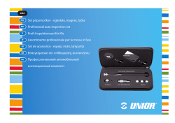
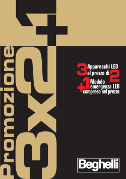
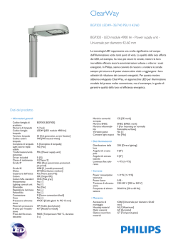
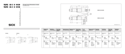
CT-MFE Printed in Germany - Doc.no. SVC 557 021 M1000 4 557 021 10 00 A2 (12/14) (DE) Betriebs- und Montageanleitung Multifunktionszeitrelais, CT-E Reihe Hinweis: Diese Betriebs- und Montageanleitung enthält nicht sämtliche Detailinformationen zu allen Typen der Produktreihe und kann auch nicht jeden Einsatzfall der Produkte berücksichtigen. Alle Angaben dienen ausschließlich der Produktbeschreibung und sind nicht als zugesicherte Eigenschaften im Rechtssinne aufzufassen. Weiterführende Informationen und Daten erhalten Sie in den Katalogen und Datenblättern der Produkte, über die örtliche ABB-Niederlassung sowie auf der ABB Homepage unter www.abb.com. Technische Änderungen jederzeit vorbehalten. In Zweifelsfällen gilt der deutsche Text. Nur von einer entsprechend qualifizierten Fachkraft zu installieren. Dabei landesspezifische Vorschriften (z.B. VDE, etc.) beachten. Vor der Installation diese Betriebs- und Montageanleitung sorgfältig lesen und beachten. Die Geräte sind wartungsfreie Einbaugeräte. (EN) Operating and installation instructions Multifunction time relay, CT-E range Note: These operating and installation instructions cannot claim to contain all detailed information of all types of this product range and can even not consider every possible application of the products. All statements serve exclusively to describe the product and have not to be understood as assured characteristics with legal force. Further information and data is obtainable from the catalogues and data sheets of this product, from the local ABB sales organisations as well as on the ABB homepage www.abb.com. Subject to change without prior notice. The German text applies in cases of doubt. The device must be installed by qualified persons only and in accordance with the specific national regulations (e.g., VDE, etc.). Before installing this unit, read these operating and installation instructions carefully and completely. The devices are maintenance-free chassis-mounted units. (FR) Instructions de montage et de mise en service Relais temporisé multifonctions, gamme CT-E Note: Ces instructions de service et de montage ne contiennent pas toutes les informations relatives à tous les types de cette gamme de produits et ne peuvent pas non plus tenir compte de tous les cas d’application. Toutes les indications ne sont données qu’à titre de description du produit et ne constituent aucunes obligations légales. Pour de plus amples informations, veuillez-vous référer aux catalogues et aux fiches techniques des produits, à votre agence ABB ou à notre site www.abb.com. Sous réserve de modifications techniques. En cas de divergences, le texte allemand fait foi. L’installation de ces produits doit être réalisée uniquement par une personne compétente et en conformité avec les prescriptions nationales (p.e. VDE, etc.). Avant l’installation de cet appareil veuillez lire l’intégralité de ces instructions. Ces produits sont des appareils encliquetables qui ne nécessitent pas d’entretien. (ES) Instrucciones de servicio y de montaje Temporizadores electrónicos, serie CT-S Nota: Estas instrucciones no contienen todas las informaciones detalladas relativas a todos los tipos del producto ni pueden considerar todos los casos de operación. Todas las indicaciones son a título descriptivo del producto y no constituyen obligaciones legales. Para más información, consulte los catálogos, las hojas de características, la sucursal local de ABB o la Web www.abb.com. Sujeto a cambios técnicos sin previo aviso. En caso de duda, prevalece el texto alemán. La instalación debe llevarse a cabo sólo por personal especializado. Es necesario respetar las normas especificas del país (p.ej. VDE, etc.). Antes de la instalación lea completamente estas instrucciones. Estos aparatos son equipos para su montaje en conjuntos y son de libre mantenimiento. (IT) Istruzioni per l’uso ed il montaggio Temporizador multifunción, serie CT-E Nota: Le presenti istruzioni per l’uso ed il montaggio non contengono tutte le informazioni di dettaglio sull‘intera gamma di prodotti e non possono trattare tutti i casi applicativi. Tutte le indicazioni servono esclusivamente a descrivere il prodotto e non sono da interpretare come caratteristiche garantite con valore di legge. Per ulteriori informazioni consultare i cataloghi ed i data sheet dei prodotti, o la nostra homepage www.abb.com, oppure rivolgersi alla filiale locale di ABB. Ci riserviamo il diritto di effettuare eventuali modifiche tecniche. In caso di discrepanze o fraintendimenti fa fede il testo in lingua tedesca. Installazione solo a cura di personale specializzato. Bisogna osservare le specifiche norme nazionali p.e. VDE, etc.). Prima dell’installazione leggere attentamente le seguenti istruzioni. Questi prodotti sono apparecchi ad incasso, che non hanno bisogno di manutenzione. (RU) Инструкция по установке и эксплуатации Многофункциональное реле времени, серия СТ-Е Примечание: Настоящая инструкция по установке и эксплуатации не претендует на полноту содержащейся здесь информации по всем типам изделий серии и не рассматривает все возможности применения настоящего изделия. Вся информация служит исключительно для его описания и не должна рассматриваться в качестве гарантированных характеристик, имеющих юридическую силу. Дополнительную информацию и данные можно получить из каталогов и листа тех. данных на настоящее изделие в местном представительстве компании АВВ, а также на сайте компании АВВ по адресу: www.abb. com. Возможны изменения без предварительного уведомления. При возникновении сомнений текст на немецком языке имеет приоритет. Устройство подлежит установке только квалифицированным персоналом в соответствии с национальными требованиями (например, VDE и т.д.). Перед началом установки данного изделия полностью и внимательно прочитайте инструкцию по установке. Устройство устанавливается на шасси и не требует обслуживания. ABB Stotz-Kontakt GmbH, Hauptstr. 14-16, 78132 Hornberg / Germany; www.abb.com/lowvoltage -> Control Products -> Electronic Relays and Controls (ZH) ֡ፕᇑҾጎኸళ ీࠀܠीۉഗLjDU.Fဣଚ I ጀᅪǖԨ֡ፕኸళփԈࡤरຍຕࢅඇևᆌᆩຫLjᆶຕ ኻਏᆶׂܔ༬ႠႜຫڦፕᆩLjᅺُփਏԢ݆ୱၳ ᆌăၘဦຫ൩֖ለरຍᄣԨईஏBCCںړӸ๚تई៓બ BCCྪበDŽ www.abb.comDžăසᆶ߸߀ທփཚኪăժᅜڤ࿔ ྺՔጚă ഗॲՂႷᆯጆᄽටᇵӀቷࡔाጆᄽࡀቤҾጎDŽස VDE DžăҾጎമLj൩ၘဦለ܁ԨҾጎኸళăׂڹ ಎփࡤඪࢆႴᄲҾጎڦևݴLj൩փᄲٶਸڹಎăׂُ ྺ௨ྼࢺڹӱҾጎഗॲă 4 1 2 0.6...0.8 Nm 5.31...7.08 lb.in Ø 4.5 mm / 0.177 in / PZ 1 10 mm 0.39 in 10 mm 0.39 in 10 mm 0.39 in 2 x 0.75...1.5 mm² 2 x 18...16 AWG 2CDC 252 048 F0009 2CDC 252 027 F0009 3 2 x 1.0...1.5 mm² 2 x 18...16 AWG 2 x 0.75...1.5 mm² 2 x 18...16 AWG 2 II Function diagrams 1 A Deutsch I 2CDC 252 131 F0205 Einstellung des Zeitbereiches durch Wahl des Endwertes: A1-A2 15-18 15-16 green LED red LED t <t B 2CDC 252 132 F0205 2 A1-A2 A1-Y1 15-18 15-16 green LED red LED t A1-A2 A1-Y1 15-18 15-16 green LED red LED t Endwert 0,05 - 1 s 0,5 - 10 s 5 - 100 s 50 - 1000 s 0,5 - 10 min 5 - 100 min 0,5 - 10 h 5 - 100 h >> 1 s >> 10 s >> 100 s >> 1000 s >> 10 min >> 100 min >> 10 h >> 100 h Absolutskala zur Einstellung des Zeitwertes innerhalb des gewählten Bereiches Auswahl der Funktion Funktionen siehe II Betriebszustandsanzeige mit LEDs U: LED grün - Steuerspeisespannung liegt an R: LED rot - Ausgangsrelais angezogen II Funktionen 1 A Ansprechverzögerung t eingestellte Verzögerungszeit Ansteuerung über Steuerspeisespannung 2 B Rückfallverzögerung mit Hilfsspannung t eingestellte Verzögerungszeit Ansteuerung über Steuereingang A1-Y1 <t 1 2CDC 252 136 F0205 4 Bereich 1 2CDC 252 135 F0205 3 Frontansicht mit Bedienelementen A1-A2 A1-Y1 15-18 15-16 green LED red LED t 3 1 Einschaltwischer t eingestellte Wischzeit Ansteuerung über Steuerspeisespannung Steuereingang A1-Y1 gebrückt 4 1 Impulsformer t eingestellte Impulszeit Ansteuerung über Steuereingang A1-Y1 t 5 Blinker, impulsbeginnend t eingestellte Blinkzeit Ansteuerung über Steuerspeisespannung Steuereingang A1-Y1 offen 6 Blinker, pausebeginnend t eingestellte Blinkzeit Ansteuerung über Steuerspeisespannung Steuereingang A1-Y1 gebrückt 2CDC 252 026 F0209 5 A1-A2 A1-Y1 15-18 15-16 green LED red LED t t 6 2CDC 252 023 F0209 Elektrischer Anschluss A1-A2 A1-Y1 15-18 15-16 green LED red LED t t Bemessungssteuerspeisespannung und Schaltbild dem seitlichen Typenschild am Gerät entnehmen. A1-A2 A1-Y1 15-16/18 Steuerspeisespannung Us 24-240 V AC/DC, 50/60 Hz Steuereingang, potentialbehaftete Ansteuerung Ausgangsrelais, 4 A / 250 V max. 3 English I Front view with operating controls Adjustment of the time range by selecting the max. value: Range Max. value 0.05 - 1 s 0.5 - 10 s 5 - 100 s 50 - 1000 s 0.5 - 10 min 5 - 100 min 0.5 - 10 h 5 - 100 h >> 1 s >> 10 s >> 100 s >> 1000 s >> 10 min >> 100 min >> 10 h >> 100 h Direct reading scale to set the time value within the chosen range Selection of the function Functions see II Indication of operational states with LEDs U: green LED - Control supply voltage applied R: red LED - Output relay energized II Functions Français I Face avant et dispositifs de commande Réglage de la plage de temporisation par sélection de la valeur maximale: Plage Valeur maximale 0,05 - 1 s 0,5 - 10 s 5 - 100 s 50 - 1000 s 0,5 - 10 min 5 - 100 min 0,5 - 10 h 5 - 100 h >> 1 s >> 10 s >> 100 s >> 1000 s >> 10 min >> 100 min >> 10 h >> 100 h Valeur absolue pour le réglage de la temporisation à l‘intérieur de la plage choisie Sélection de la fonction Pour les fonctions voir II Indication de fonctionnement par LED U: LED verte - Tension d‘alimentation de commande appliquée R: LED rouge - Relais de sortie activé II Fonctions 1 A ON-delay t adjusted time delay Triggering via control supply voltage 1 A Temporisation au travail t temporisation ajustée Activation par la tension d‘alimentation de commande 2 B OFF-delay with auxiliary voltage t adjusted time delay Triggering via control input A1-Y1 2 B Temporisation au repos avec tension auxiliaire t temporisation ajustée Activation par l‘entrée de commande A1-Y1 3 1 Impulse-ON t adjusted pulse time Triggering via control supply voltage Control input A1-Y1 jumpered 3 1 Contact de passage à l‘excitation t temps d‘impulsion ajusté Activation par la tension d‘alimentation de commande Entrée de commande A1-Y1 pontée 4 1 Pulse former t adjusted pulse time Triggering via control input A1-Y1 4 1 Formateur d‘impulsion t temps d‘impulsion ajusté Activation par l‘entrée de commande A1-Y1 5 Flasher starting with ON t adjusted flashing time Triggering via control supply voltage Control input A1-Y1 open 5 Clignotant démarrant par marche t temps de clignotement ajusté Activation par la tension d‘alimentation de commande Entrée de commande A1-Y1 ouverte 6 Flasher starting with OFF t adjusted flashing time Triggering via control supply voltage Control input A1-Y1 jumpered 6 Clignotant démarrant par arrêt t temps de clignotement ajusté Activation par la tension d‘alimentation de commande Entrée de commande A1-Y1 pontée Electrical connection Raccordement électrique For the rated control supply voltage and the circuit diagram, see label at the side of the unt. A1-A2 A1-Y1 15-16/18 Control supply voltage Us 24-240 V AC/DC, 50/60 Hz Control input, voltage-related triggering Output relay, 4 A / 250 V max. Pour la tension assignée d‘alimentation de commande et pour le schéma des connexions voir l‘étiquette placée sur le côté du relais. A1-A2 A1-Y1 15-16/18 Tension d‘alimentation de commande Us 24-240 V AC/DC, 50/60 Hz Entrée de commande, excitation par tension Relais de sortie, 4 A / 250 V max. 4 Italiano Español I Vista frontal con elementos de mando Ajuste del margen de tiempo para selección del valor fondo escala: I Vista frontale con gli elementi di comando Impostazione del campo di temporizzazione mediante selezione del valore massimo del campo: Margen Fondo escala Campo Valore massimo 0,05 - 1 s 0,5 - 10 s 5 - 100 s 50 - 1000 s 0,5 - 10 min 5 - 100 min 0,5 - 10 h 5 - 100 h >> 1 s >> 10 s >> 100 s >> 1000 s >> 10 min >> 100 min >> 10 h >> 100 h 0,05 - 1 s 0,5 - 10 s 5 - 100 s 50 - 1000 s 0,5 - 10 min 5 - 100 min 0,5 - 10 h 5 - 100 h >> 1 s >> 10 s >> 100 s >> 1000 s >> 10 min >> 100 min >> 10 h >> 100 h Escala absoluta para el ajuste del valor de temporización dentro de margen seleccionado Scala a lettura diretta per l‘impostazione del tempo all‘interno del campo selezionato Selección de la función Funciones: vease II Selezione della funzione Funzioni: vedi II Indicador de servicio con LEDs U: LED verde - Tensión de alimentación aplicada R: LED rojo - Relé de salida energizado LED di visualizzazione dello stato di funzionamento U: LED verde - Tensione d‘alimentazione applicata R: LED rosso - Relè di uscita eccitato II Funciones II Funzioni 1 A Retardo a la conexión t tiempo de retardo ajustado Disparo a través de la tensión de alimentación 1 A Ritardo all‘eccitazione t tempo di ritardo impostato Pilotaggio mediante la tensione d‘alimentazione 2 B Retardo a la desconexión con tensión auxiliar t tiempo de retardo ajustado Disparo a través de la entrada de mando A1-Y1 2 B Ritardo alla diseccitazione con tensione ausiliaria t tempo di ritardo impostato Pilotaggio mediante l‘ingresso di comando A1-Y1 3 1 Pulso a la conexión t tiempo de pulso ajustado Disparo a través de la tensión de alimentación Entrada de mando A1-Y1 puenteado 3 1 Impulso all‘eccitazione t tempo d‘impulso impostato Pilotaggio mediante la tensione d‘alimentazione Ingresso di comando A1-Y1 ponticellato 4 1 Pulso inicial t tiempo de pulso ajustado Disparo a través de la entrada de mando A1-Y1 4 1 Generatore d‘impulso t tempo d‘impulso impostato Pilotaggio mediante l‘ingresso di comando A1-Y1 5 Intermitencia, inicio en ON t tiempo de intermitencia ajustado Disparo a través de la tensión de alimentación Entrada de mando A1-Y1 abierto 5 Lampeggiatore, inizio con ON t tempo di lampeggiamento impostato Pilotaggio mediante la tensione d‘alimentazione Ingresso di comando A1-Y1 aperto 6 Intermitencia, inicio en OFF t tiempo de intermitencia ajustado Disparo a través de la tensión de alimentación Entrada de mando A1-Y1 puenteado 6 Lampeggiatore, inizio con OFF t tempo di lampeggiamento impostato Pilotaggio mediante la tensione d‘alimentazione Ingresso di comando A1-Y1 ponticellato Conexión eléctrica Collegamento elettrico Véase la etiqueta lateral de características para la tensión nominal de alimentación y para el esquema contactos. Per la tensione nominale d‘alimentazione e per lo schema elettrico, vedi la targhetta laterale del relè. A1-A2 A1-A2 A1-Y1 15-16/18 Tensión de alimentación Us 24-240 V AC/DC, 50/60 Hz Entrada de mando, disparo con potencial Relé de salida, 4 A / 250 V max. A1-Y1 15-16/18 Tensione d‘alimentazione Us 24-240 V AC/DC, 50/60 Hz Ingresso di comando, pilotaggio con tensione di riferimento Relè di uscita, 4 A / 250 V max. 5 Русский I Вид спереди на элементы управления Регулировка временного диапазона путем установки макс. значения: Диапазон Макс. значение 0.05 - 1 с 0.5 - 10 с 5 - 100 с 50 - 1000 с 0.5 - 10 мин 5 - 100 мин 0.5 - 10 ч 5 - 100 ч >> 1 с >> 10 с >> 100 с >> 1000 с >> 10 мин >> 100 мин >> 10 ч >> 100 ч Шкала в абсолютных значениях для установки точного значения времени в пределах выбранного диапазона Выбор функции Функции: см. главу II Индикация рабочего состояния при помощи СИД U: зеленый СИД - Подано напряжение питания R: красный СИД - Выходное реле возбужденно Chinese I മ௬ӱ֡ፕ ۙব้क़ڦྷݔፌٷኵǖ! ྷݔ ፌٷኵ 0.05 - 1 s 0.5 - 10 s 5 - 100 s 50 - 1000 s 0.5 - 10 min 5 - 100 min 0.5 - 10 h 5 - 100 h >> 1 s >> 10 s >> 100 s >> 1000 s >> 10 min >> 100 min >> 10 h >> 100 h ሞ้ۨڦक़ాྷݔLjথਗ਼܈ಎย้ۨक़ኵ ้क़ࠀీስ ࠀీ֖ੂJJ LEDጒༀኸ๖ U;୴!LED U;ࢤ!LED . ࠃۉۉუฉۉ .!ीۉഗۯፕ II ࠀీ II Функции 1 A 2 B 3 1 4 1 Задержка при срабатывании t регулируемое время задержки Срабатывание через управляющее напряжение Выдержка при отпускании (ВЫКЛ.) со вспомогательным напряжением t регулируемое время задержки Срабатывание через управляющий вход A1-Y1 Импульс при срабатывании (ВКЛ.) t регулируемое время импульса Срабатывание через управляющее напряжение Перемычка на управляющ. входе A1-Y1 1 A ཚۉჽ้ t ჽ้क़ۙব! ཚࡗ੦ࠃۉۉუ݀ة 2 B ۉჽ้LjႴޤዺۉᇸ t ჽ้क़ۙব! ཚࡗ੦A1-Y1݀ة 3 1 ཚۉஞ؋ჽ้.ON t ஞ؋้क़ۙব ੦A1-Y1܌থLjཚࡗ੦ࠃۉۉუ݀ة 4 1 ڇஞ؋݀ิഗ! t!!!ஞ؋้क़ۙব! ཚࡗ੦A1-Y1݀ة Формирователь импульсов, t регулируемое время импульса Срабатывание через управляющий вход A1-Y1 5 ཚۉຮLjᅜONDŽଋༀDžਸ๔! t!!!ຮ้क़ۙব! ੦A1-Y1ٶਸLjཚࡗ੦ࠃۉۉუ݀ة 5 Мигание с началом импульса t регулируемое время мигания Срабатывание через управляющее напряжение Управляющий вход A1-Y1 разомкнут 6 ཚۉຮLjᅜOFFDŽӁༀDžਸ๔! t!!!ຮ้क़ۙব! ੦A1-Y1܌থLjཚࡗ੦ࠃۉۉუ݀ة 6 Мигание с началом паузы t регулируемое время мигания Срабатывание через управляющее напряжение Перемычка на управляющ. входе A1-Y1 ۉഘথ ۨܮ੦ࠃۉۉუࢅ࣮ୟLj൩֖९้क़ीۉഗ ֨௬ڦՔധ Электрическое подключение Номинальное напряжение питания и схему соединений см. на этикетке на боку прибора A1-A2 A1-Y1 15-16/18 A1-A2 A1-Y1 15-16/18 Us!ࠃۉۉუ 24-240 V AC/DC, 50/60 Hz ੦Ljۉუ၎࠲ۅة ीۉഗ, 4 A / 250 V max. Напряжение питания Us 24-240 В AC/DC, 50/60 Гц Управляющий вход для запуска временных функций Выходное реле, 4 A/250 В макс. 6
© Copyright 2026 Paperzz