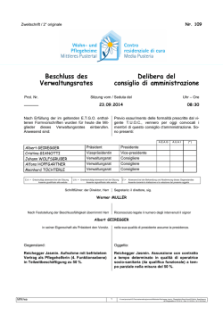
Istruzioni per installazione, uso e manutenzione
Montage und Bedienungs Anleitung
Installation, use and maintenance instructions
Manuel d’entretien
I
Bruciatore di nafta
D
Heizölbrenner
GB
F
Heavy oil burner
Brûleur à fioul lourd
Funzionamento bistadio
Zweistufiger Betrieb
Two-stage operation
Fonctionnement à deux allures
CODICE
CODE
MODELLO - MODELL
MODELE - MODEL
TIPO - TYP
TYPE
3435023
PRESS 60 N/ECO
628 T
3435024
PRESS 60 N/ECO
628 T
2916194 (1) - 01/2009
INDICE
1.
1.1
DESCRIZIONE DEL BRUCIATORE. . . . . . 1
Materiale a corredo . . . . . . . . . . . . . . . . . . 1
2.
2.1
2.2
2.3
DATI TECNICI . .
Dati tecnici . . . . .
Dimensioni . . . . .
Campo di lavoro .
3.
3.1
3.2
3.3
INSTALLAZIONE. . . . . . . . . . . . . . . . .
Impianti alimentazione olio combustibile .
Impianto elettrico . . . . . . . . . . . . . . . . .
Collegamenti elettrici . . . . . . . . . . . . . .
1.
.
.
.
.
.
.
.
.
.
.
.
.
.
.
.
.
.
.
.
.
.
.
.
.
.
.
.
.
.
.
.
.
..
..
..
..
...
...
...
...
....
....
....
....
4.
4.1
4.2
4.3
4.4
4.5
4.6
4.7
4.8
4.9
4.10
4.11
...2
...2
...2
...2
.
.
.
.
.
.
.
.
.
.
.
.
3
3
4
5
FUNZIONAMENTO . . . . . . . . . . . . . . . . . . 6
Scelta degli ugelli . . . . . . . . . . . . . . . . . . . 6
Pressione della pompa . . . . . . . . . . . . . . . 6
Regolazione testa di combustione . . . . . . . . 6
Regolazione motorino serranda aria . . . . . . . 6
Pressostato aria . . . . . . . . . . . . . . . . . . . . . . 7
Regolazione temperatura di polverizzazione . 7
Programma di avviamento . . . . . . . . . . . . . . 9
Bruciatori per oli ecologici . . . . . . . . . . . . . . . 9
Funzionamento con nafta emulsionata . . . . . 9
Diagnostica programma di avviamento . . . . 10
Diagnostica mal funzionamento . . . . . . . . . 10
DESCRIZIONE DEL BRUCIATORE
Bruciatore di nafta con funzionamento bistadio.
O Il bruciatore risponde al grado di protezione IP 40 secondo EN 60529.
O Bruciatore con marcatura CE in conformità alle Direttive CEE: CEM 89/336/CEE, Bassa Tensione
73/23/CEE, Macchine 98/37/CEE.
Fig. 1
2893
1
2
3
4
5
6
7
Raccordo di aspirazione
Raccordo di ritorno
Regolatore pressione pompa
Attacco manometro (G1/8)
Attacco vacuometro (G1/2)
Motorino apriserranda
Pulsante di sblocco apparecchiatura con
segnalazione di blocco
8 - Sblocco salvamotore ventilatore
9 - Vite regolazione testa di combustione
10 - Doppio filtro
1.1
-
11
12
13
14
15
16
17
18
19
20
21
-
Gruppo valvole
Manometro con rubinetto di protezione
Termostato di regolazione
Contattore preriscaldatore
Trasformatore
Morsettiera
Bocchettoni pressacavo
Valvola antigas
Termometro
Avviatore motore pompa con sblocco
Pressostato aria
MATERIALE A CORREDO
Tubi flessibili . . . . . . . . . . . . . . . . . . . . . . . . . . . . .
Guarnizioni . . . . . . . . . . . . . . . . . . . . . . . . . . . . . .
Schermo per flangia . . . . . . . . . . . . . . . . . . . . . . .
Prolunghe per guide (per versione testa allungata)
Raccordo per funzionamento con nafta
emulsionata (vedere pag. 9). . . . . . . . . . . . . . . . .
. . N° 2
. . N° 2
. . N° 1
. . N° 2
Nipples . . . . .
Viti . . . . . . . .
Ugelli . . . . . .
Guarnizione .
. . N° 1
6194
1
I
...
...
...
...
....
....
....
....
....
....
....
....
...
...
...
...
..
..
..
..
.
.
.
.
.
.
.
.
.
.
.
.
. N° 2
. N° 4
. N° 2
. N° 1
2.
DATI TECNICI
2.1
DATI TECNICI
TIPO
Potenza termica - Portata
Combustibile
Alimentazione elettrica
Motore
230V - 400V
Trasformatore d’accensione
Riscaldatori
Potenza elettrica assorbita
Pompa
2.2
628 T
171/342 ÷ 684 kW
–
15/30 ÷ 60 kg/h
Olio viscosità max. a 50° C 115 mm2/s (15° E)
Trifase, 230 V ± 10% ~ 50Hz senza neutro
con neutro
400 V ± 10% ~ 50Hz
Ventilatore:
3,4A - 2A
Pompa:
2,1A - 1,2A
Primario 2 A – Secondario 2 x 6,5 kV – 35 mA
4,2 kW
5,9 kW
100 kg/h a 20 bar
DIMENSIONI
Piastra caldaia
Bruciatore
834
245
400
625
*
335
Ø172
290
D2715
79
D2686
NOTA
Il peso del gruppo pompante nella parte posteriore sollecita a flessione le guide; si consiglia di sostenere il
bruciatore in fase di estrazione per non danneggiare il disco fiamma e le guide stesse.
*
Per versione testa allungata.
Per l’arretramento del bruciatore servirsi delle prolunghe ai perni fornite a corredo.
2.3
CAMPO DI LAVORO (2 ugelli funzionanti)
Pressione in camera di
combustione – mbar
D2723
kg/h
kW
Potenzialità bruciatore
Quando il bruciatore funziona con un solo ugello, le condizioni di pressurizzazione sono più favorevoli e
non pongono problemi. Portata minima con un solo ugello: 15 kg/h - 171 kW.
6194
2
I
3.
INSTALLAZIONE
3.1
IMPIANTI ALIMENTAZIONE OLIO COMBUSTIBILE
IMPIANTO PER GRAVITÀ
Per olio leggero con viscosità max. 7°E / 50°C.
H
max. 30m
Innesco pompa:
allentare il tappo dall’attacco vacuometro
(5, fig. 1) ed attendere la fuoriuscita del
combustibile.
H: Dislivello
L: Lunghezza del tubo di aspirazione
D2720
L metri
ø 1”
ø 1 1/4”
gas
gas
6
10
11
17
16
24
21
31
26
38
H
metri
0
0,5
1
1,5
2
max. 30m
H
IMPIANTO IN ASPIRAZIONE
Per olio leggero con viscosità max. 7°E / 50°C.
H
D2721
Sconsigliato, a meno che non ci si trovi
in presenza di un impianto già preesistente.
Non si deve superare la depressione max.
di 0,5 bar (38 cm Hg) misurata all’attacco
vacuometro (5, fig. 1).
Si raccomanda che le tubazioni siano a
perfetta tenuta. Quando la cisterna è ad un
livello inferiore del bruciatore, si consiglia
di far arrivare la tubazione alla stessa altezza della tubazione di aspirazione.
In questo caso non è necessaria la valvola
di fondo.
H
metri
0
0,5
1
1,5
2
2,5
3
L metri
ø 1 1/4” ø 1 1/2”
gas
gas
22
45
19
39
16
33
13
27
10
21
7
15
0
8
IMPIANTO AD ANELLO (pressione max. anello 3 bar)
Per olio denso con viscosità fino a 50°E / 50°C.
D2631
1
2
3
4
-
Cisterna (riscaldata per olio denso)
Filtro (con resistenza per olio > 7°E / 50°C)
Bruciatore
Saracinesche per esclusione bruciatore (accoppiate)
5
6
7
8
-
Pompa di trasferimento
Manometro di controllo
Pompa bruciatore
Regolatore di pressione
Nota importante: per agevolare il flusso di combustibile tutte le tubazioni devono essere opportunamente
dimensionate, coibentate e riscaldate. (elettricamente o tramite vapore o acqua calda).
Attenzione: accertarsi prima di mettere in funzionamento il bruciatore che il tubo di ritorno non abbia occlusioni.
Un eventuale impedimento provocherebbe la rottura dell’organo di tenuta della pompa.
6194
3
I
3.2
IMPIANTO ELETTRICO DEL BRUCIATORE (eseguito in fabbrica)
RMO88.53A2
TB
12 15
11
16 18 9
5 1
A
8 13
17
FR
TE
TA
2
S
5
ST2
3
4
1
2 4 6
R1
96
R2
2 4 6
RT
P
P PA
A2
1 3 5 13
2 4 6
Tm
CMV
M
TB TAV
MP M
3
RT1
1 2
95
14
A1
V1
V2
96
14
R3
T2 T6 T8
V22
L N S3 T1 30
V21
L1R
L2R
L3R
L1 L2 L3
L1P
L2P
L3P
1 3 5 13
N
95
A2
CMP
TB
MB
- M +
MV
M
3
R1
1 3 5
CR
A2
TB
R2
1 2 3 4 5 6 7 8 9
A1
ST1
TM
F
SM
7
8
6
11
10
MV2 HS1 ST0
4
2615
CMP Contattore motore pompa
RT
CR
Contattore preriscaldatore
RT1 Relè termico motore pompa
F
Soppressore
S
Serbatoio preriscaldatore
FR
Fotoresistenza
SM
Servomotore
MB
Morsettiera bruciatore
TA
Trasformatore d’accensione
MP
Motore pompa
TB
Terra bruciatore
MV
Motore ventilatore
TE
PA
Pressostato aria
Termostato di regolazione e consenso
di avviamento
R1
Resistenza portaspruzzo
Tm
Termostato a contatto di minima
R2
Resistenza pompa
TM
Termostato a contatto di massima
R3
Resistenza gruppo valvole
V1
Valvola 1° stadio
V2
Valvola 2° stadio
RMO Apparecchiatura elettrica
6194
4
I
Relè termico motore ventilatore
A1
3.3
COLLEGAMENTI ELETTRICI ALLA MORSETTIERA (a cura dell’installatore)
2616
A Ampere
B Ampere
C Ampere
D mm2
E mm2
F mm2
IN
Interruttore manuale
TL
Telecomando di limite
MB
Morsettiera bruciatore
TR
Telecomando di regolazione
H
Segnalazione di blocco
TS
Telecomando di sicurezza
230V
10
6
16
1,5
2,5
4
400V
6
4
10
1,5
1,5
2,5
COLLEGAMENTI
RESISTENZE
PRERISCALDATORE
NOTA
y Sezione dei conduttori: min. 1 mm2.
(Salvo diverse indicazioni di norme e leggi locali).
y Per alimentazione a 230V collegare a triangolo il ser-
batoio ed il motore (il collegamento originale é a stella
per 400V).
FUNZIONAMENTO BISTADIO
Si ottiene mediante il telecomando collegato ai morsetti 5-6
(togliendo il ponte) che comanda la seconda valvola.
D2692
FISSAGGIO CAVI ELETTRICI
Tutti i cavi elettrici da collegare alla morsettiera (16, fig. 1) vanno fatti passare per gli opportuni bocchettoni a
pressacavo (17, fig. 1), vedi figura seguente.
1 - Alimentazione monofase resistenze
preriscaldate: . . . . . . . . . . . . . . . . . . . . . . .bocchettone Pg 21
2 - Alimentazione trifase motore: . . . . . . . . . .bocchettone Pg 16
3 - Alimentazione monofase e termostato
sicurezza: . . . . . . . . . . . . . . . . . . . . . . . . .bocchettone Pg 13,5
4 - Termostato regolazione: . . . . . . . . . . . . . .bocchettone Pg 13,5
5 - Termostato 2° stadio: . . . . . . . . . . . . . . . .bocchettone Pg 13,5
D2635
Eventuali altre segnalazioni o comandi possono essere collegati alla morsettiera del bruciatore asportando la pastiglia metallica dal foro pretranciato e inserendo un comune bocchettone a pressacavo per il passaggio e fissaggio dei cavi. Per garantire il grado di protezione IP 40 secondo EN 60529 chiudere i fori di passaggio dei cavi
di eventuali bocchettoni inutilizzati con opportune pastiglie.
NOTE
- Eseguire un buon collegamento di terra.
- Verificare l’arresto del bruciatore aprendo il termostato di caldaia e il blocco oscurando la fotoresistenza.
6194
5
I
4.
FUNZIONAMENTO
4.1
SCELTA DEGLI UGELLI
Ugelli consigliati:
- Monarch F 80 H0.
4.2
PRESSIONE DELLA POMPA
Pressione consigliata:
- Olio fluido: 20 bar
- Olio denso: 25 bar
Le portate degli ugelli indicate in tabella sono nominali,
ricavate per un olio combustibile leggero (viscosità 3 ÷ 5 °E
a 50 °C riscaldato a 100 °C). La portata reale può variare
rispetto a quella nominale del ± 5%.
Se si desiderano valori intermedi di portata rispetto a quelli
indicati nella tabella è possibile variare la pressione in
pompa o comporre diversamente gli ugelli.
La pompa lascia la fabbrica tarata a 20 bar.
4.3
Ugello
GPH (45° - 60°)
20 bar
kg/h
25 bar
kg/h
2,50 + 2,50
30,00
34,00
3,00 + 3,00
36,00
40,60
3,50 + 3,50
42,00
47,40
4,00 + 4,00
48,00
54,20
4,50 + 4,50
54,00
61,00
5,00 + 5,00
60,00
–
kg/h
D2693
REGOLAZIONE TESTA DI COMBUSTIONE
Si effettua ruotando la vite A, fig. 2 fino a che la tacca, rilevata
dal diagramma, collima con il piano del manicotto B, fig. 2.
Fig. 2
B
Tacca 4
D2637
A
n° tacche
4.4 REGOLAZIONE MOTORINO SERRANDA
ARIA
SOSTA - Leva azzurra
La leva azzurra è posizionata in fabbrica verticalmente e corrisponde alla condizione di serranda aria totalmente chiusa.
Per avere un’apertura parziale della serranda, spostare tale
leva verso sinistra (segno + sulla targhetta).
La nuova posizione della serranda potrà essere verificata
con l’arresto del bruciatore.
Non superare, in ogni caso, la posizione della leva arancio di
1° stadio.
PRIMO STADIO - Leva arancio
La leva arancio regola la posizione della serranda di prima
fiamma, ed è tarabile sia in apertura che in chiusura.
SECONDO STADIO - Leva rossa e nera
La leva rossa regola la posizione della serranda di seconda
fiamma, ed è tarabile sia in apertura che in chiusura.
La leva nera comanda l’apertura della seconda valvola olio
e deve sempre anticipare di poco la leva rossa, ma mai la
leva arancio di 1° stadio.
6194
6
I
D2638
Leva nera
Leva rossa
Leva arancio
Leva azzurra
Apertura +
– Chiusura
4.5
PRESSOSTATO ARIA
Eseguire la regolazione del pressostato aria dopo aver
effettuato tutte le altre regolazioni del bruciatore con il
pressostato aria regolato a inizio scala.
Con il bruciatore funzionante alla potenza MIN aumentare la pressione di regolazione girando lentamente in
senso orario l'apposita manopolina fino al blocco del
bruciatore.
Girare quindi la manopolina in senso antiorario di un
valore pari a circa il 20% del valore regolato e verificare successivamente il corretto avviamento del bruciatore. Se il bruciatore blocca nuovamente, girare
ancora un poco la manopolina in senso antiorario.
D521
4.6
REGOLAZIONE TEMPERATURA DI POLVERIZZAZIONE
Termostati di regolazione - di minima - di massima
Il termostato di regolazione impedisce l’avviamento del bruciatore se la temperatura del combustibile non ha
raggiunto il valore necessario per una buona polverizzazione come indicato nel diagramma seguente.
mm2/s °E
Viscosità a 50° C
D2694
Manopola di regolazione
termostato
Preriscaldatore
Scarico impurità
Temperatura di polverizzazione
D2719
Esempio
Un olio combustibile 7 °E a 50 °C va preriscaldato a 110 °C.
Il termostato deve essere generalmente tarato ad un valore di temperatura superiore di quello desiderato
(120° letti sulla manopola per avere circa 100 °C agli ugelli).
La lettura va fatta dopo qualche minuto di funzionamento, poi effettuare i necessari ritocchi.
Il termostato a contatto di minima interviene arrestando il bruciatore nel caso che la temperatura del combustibile scenda sotto il valore necessario per aver una buona combustione.
Il termostato a contatto di massima disinserisce le resistenze quando, a causa di un’avaria del termostato
di regolazione, si registra un sensibile aumento della temperatura nel preriscaldatore. In caso di interventi
anomali accertarsi del regolare funzionamento del termostato di regolazione e della resistenza a contatto
della sonda del termostato stesso. Viene tarato in fabbrica a 180 °C.
6194
7
I
NOTE IMPORTANTI
Tubazioni tavoletta
Sostituzione dei termostati di preriscalatore.
Riposizionare le sonde dei nuovi termostati, dopo aver
allentato le viti di fissaggio del pacco tavolette, avendo
Tavoletta
cura che la sonda sia a contatto delle tubazioni e della
Resistenza
resistenza come in figura lato. Valgono le stesse precauzioni nel caso di sostituzione delle resistenze a
contatto delle sonde dei termostati.
Nel caso che durante il funzionamento si registrassero
D2751
Sonda del termostato
elevati scarti o punte eccessive di temperatura, verificare con un ohmetro la continuità della resistenza posta a contatto della sonda di temperatura (valore circa
35 Ohm).
Utilizzare soltanto filtri con una scanalatura sull’esagono di avvitamento.
NOTE
y Il preriscaldatore può essere dotato di un secondo termostato a contatto di massima.
Questo termostato può essere impiegato per agire da interruttore su un contattore esterno per togliere corrente al preriscaldatore in caso di sovratemperatura (kit cod. 3000800).
y Prima dell’avviamento del bruciatore è consigliabile accertarsi che la pompa sia piena di combustibile per non
farla girare a secco per troppo tempo.
y Pulizia dei filtri:
deve essere eseguita periodicamente per non causare inconvenienti al funzionamento del bruciatore.
y Filtro di linea:
posto in aspirazione, provoca l’aumento della depressione in pompa con conseguente rumorosità della stessa. Non superare un valore di depressione, misurato all’attacco vacuometro (5, fig. 1), di 38 cm Hg (5 m.c.a.).
y Filtro preriscaldatore (10, fig. 1):
posto in mandata, provoca una diminuzione della pressione di polverizzazione controllabile al manometro
(12, fig. 1).
RUBINETTO DI PROTEZIONE MANOMETRO
Una volta controllata la pressione di polverizzazione in funzionamento, è conveniente escludere il manometro
(12, fig. 1) dai colpi di pressione che subisce ad ogni avviamento del bruciatore.
Per questo, a bruciatore fermo e manometro a 0 bar, chiudere il rubinetto di protezione.
6194
8
I
4.7
PROGRAMMA DI AVVIAMENTO
Normale
Blocco per mancata accensione
Termostato
Motori
Trasf. d’accensione
Valvola 1a fiamma
Valvola 2a fiamma
Spia di blocco
2894
Blocco motori
É provocato dal relè termico salvamotore in caso di sovraccarico o di mancanza di fase
4.8
BRUCIATORI PER OLI ECOLOGICI
AVVERTENZA
Il passaggio da olio combustibile normale a olio combustibile ecologico richiede obbligatoriamente:
y Svuotamento della cisterna dall’olio combustibile normale.
y Pulizia della cisterna e della tubazione che porta il combustibile al bruciatore.
y Applicazione di un filtro, se già non esiste, sul condotto di alimentazione del bruciatore con grado di filtraggio
0,3 mm massimo.
In assenza di questi provvedimenti, la Riello S.p.A. declina ogni responsabilità nel caso di precoce usura o malfunzionamento del bruciatore.
NOTE
Questi bruciatori sono frutto di accurati studi che hanno permesso il funzionamento anche con oli combustibili
ecologici; oli che in certe condizioni di temperatura e velocità, sono particolarmente aggressivi per gli organi vitali del bruciatore.
L’obiettivo é stato raggiunto con la riduzione della velocità di attraversamento in alcuni organi e la scelta appropriata dei materiali (in particolare dei trattamenti delle superfici) nonché con una ridefinizione dei giochi e delle
tolleranze di accoppiamento.
I bruciatori per oli ecologici si differenziano estremamente dai bruciatori per oli combustibili normali per l’adozione di una pompa separata (azionata da un proprio motore a 1400 giri/minuto) e per la presenza di doppia filtrazione tra pompa ed ugello.
4.9
FUNZIONAMENTO CON NAFTA EMULSIONATA
D3435
6194
9
I
AVVERTENZA
In caso di funzionamento con nafta
emulsionata è necessario sostituire il
raccordo a bordo del bruciatore (*)
con quello fornito a corredo dello
stesso.
4.10 DIAGNOSTICA PROGRAMMA DI AVVIAMENTO
Durante il programma di avviamento, le indicazioni sono esplicate nella seguente tabella:
TABELLA CODICE COLORE
Sequenze
Codice colore
Preventilazione
Fase di accensione
Funzionamento con fiamma ok
Funzionamento con fiamma debole
Alimentazione elettrica inferiore a
~ 170V
Blocco
Luce estranea
Legenda:
Spento
Giallo
Verde
Rosso
4.11 DIAGNOSTICA MAL FUNZIONAMENTO
L’apparecchiatura in dotazione ha una sua funzione diagnostica attraverso la quale è possibile facilmente individuare le possibili cause di mal funzionamento (segnalazione: LED ROSSO).
Per utilizzare tale funzione, bisogna aspettare almeno dieci secondi dall’istante di messa in sicurezza dell’apparecchiatura e premere il pulsante di sblocco per un tempo minimo di tre secondi.
Rilasciato il pulsante, il LED ROSSO comincerà a lampeggiare, come illustrato nella seguente figura.
LED ROSSO acceso
aspettare per almeno 10 s
premere pulsante
per > 3 s
segnale
Intervallo
3s
segnale
Gli impulsi del LED costituiscono un segnale intervallato da 3 secondi circa.
Il numero degli impulsi darà le informazioni sui possibili guasti, secondo la seguente tabella:
SEGNALE
CAUSA PROBABILE
2 lampeggi
Non viene rilevato un segnale stabile di fiamma nel tempo di sicurezza:
– guasto alla fotoresistenza;
– guasto alla valvola olio;
– inversione fase/neutro;
– guasto al trasformatore di accensione
– bruciatore non regolato (nafta insufficiente).
3 lampeggi
Il pressostato aria di minima (se installato) non chiude:
– guasto al pressostato aria;
– pressostato aria non regolato;
– intervento del pressostato aria di massima (se installato).
4 lampeggi
Il pressostato aria di minima (se installato) non commuta, oppure luce presente in
camera prima dell’accensione:
– guasto al pressostato aria;
– pressostato aria non regolato.
7 lampeggi
Sparizione della fiamma durante il funzionamento:
– bruciatore non regolato (nafta insufficiente);
– guasto alla valvola olio;
– cortocircuito tra la fotoresistenza e la terra.
8 lampeggi
– Guasto termostato di consenso olio;
– Interruzione resistenze riscaldanti.
10 lampeggi
– Errore di collegamento o guasto interno.
6194
10
I
INHALT
1.
1.1
BESCHREIBUNG DES BRENNERS . . . . . 1
Mitgeliefertes Zubehör . . . . . . . . . . . . . . . . 1
2.
2.1
2.2
2.3
TECHNISCHE MERKMALE .
Technische Daten . . . . . . . .
Abmessungen . . . . . . . . . . .
Betriebsbereich . . . . . . . . . .
.
.
.
.
.
.
.
.
.
.
.
.
.
.
.
.
.
.
.
.
.
.
.
.
.
.
.
.
2
2
2
2
3.
3.1
3.2
3.3
INSTALLATION . . . . . . . . . . . . . . .
Brennstoffzuführung . . . . . . . . . . . .
Elektrisches Verdrahtungsschema .
Elektrische Anschlüsse . . . . . . . . .
.
.
.
.
.
.
.
.
.
.
.
.
.
.
.
.
.
.
.
.
.
.
.
.
3
3
4
5
1.
.
.
.
.
.
.
.
.
.
.
.
.
.
.
.
.
4.
4.1
4.2
4.3
4.4
4.5
4.6
4.7
4.8
4.9
4.10
4.11
BETRIEB . . . . . . . . . . . . . . . . . . . . . . . . . 6
Wahl der Düsen . . . . . . . . . . . . . . . . . . . . 6
Pumpendruck . . . . . . . . . . . . . . . . . . . . . . 6
Einstellung des Brennerkopfes . . . . . . . . . . . 6
Luftklappenmotorregulierung. . . . . . . . . . . . . 6
Luftdruckwächter . . . . . . . . . . . . . . . . . . . . . . 7
Einstellung der Zerstäubungstemperatur . . . .7
Betriebsablauf . . . . . . . . . . . . . . . . . . . . . . . . 9
Brenner für Öko-Heizöle . . . . . . . . . . . . . . . . 9
Betrieb mit Heizöl-Emulsion . . . . . . . . . . . . . 9
Diagnostik Betriebsablauf . . . . . . . . . . . . . . 10
Diagnostik Betriebsstörungen . . . . . . . . . . . 10
BESCHREIBUNG DES BRENNERS
Heizölbrenner mit zweistufigem Betrieb.
O Der Brenner entspricht der Schutzart IP 40 gemäß EN 60529.
O Brenner mit CE-Kennzeichnung gemäß der EWG-Richtlinien: EMV 89/336/EWG, Niederspannungs-
richtlinie 73/23/EWG und Maschinenrichtlinie 98/37/EWG.
Abb. 1
2893
1
2
3
4
5
6
7
8
9
10
11
-
1.1
Vorlaufanschluss
Rücklaufanschluss
Pumpendruckeinstellung
Manometeranschluss (G1/8)
Vakuummeteranschluss (G1/2)
Luftklappenmotorregulierung
Entstörtaste mit Signal
Entstörung Motorschutzschalter des Gebläses
Schraube zur Einstellung des Brennerkopfes
Doppelfilter
Ventilgruppe
12
13
14
15
16
17
18
19
20
21
-
Manometer mit Schutzabsperrhahn
Einstellbarer Thermostat
Kontaktgeber des Vorwärmers
Transformator
Klemmleiste
Stopfbuchsverschraubungen
Gegengasbildungventil
Thermometer
Anlasser Pumpenmotor mit Entstörung
Luftdruckwächter
MITGELIEFERTES ZUBEHÖR
Schläuche . . . . . . . . . . . . . . . . . . . . . . . . . . . .
Dichtungen . . . . . . . . . . . . . . . . . . . . . . . . . . . .
Flanschdichtung . . . . . . . . . . . . . . . . . . . . . . . .
Führungsverlängerungen (für Version . . . . . . .
verlängerter Brennerkopf) . . . . . . . . . . . . . . . .
Anschluss für den Betrieb mit Heizöl-Emulsion
(siehe S. 9) . . . . . . . . . . . . . . . . . . . . . . . . . . .
.
.
.
.
.
.
.
.
.
.
.
.
.
.
.
.2 St.
.2 St.
.1 St.
....
.2 St.
Nippel. . . .
Schrauben
Düsen . . .
Dichtung .
. . . .1 St.
6194
1
D
.
.
.
.
.
.
.
.
.
.
.
.
.
.
.
.
.
.
.
.
.
.
.
.
.
.
.
.
.
.
.
.
.
.
.
.
.
.
.
.
.
.
.
.
.
.
.
.
.
.
.
.
.
.
.
.
.
.
.
.
.
.
.
.
.
.
.
.
.
.
.
.
.
.
.
.
.
.
.
.
.
.
.
.
.2 St.
.4 St.
.2 St.
.1 St.
2.
TECHNISCHE DATEN
2.1
TECHNISCHE DATEN
TYP
Wärmeleistung - Durchsatz
Brennstoff
Stromversorgung
Motor
230V - 400V
Zündtransformator
Heizpatronen
Leistungsaufnahme
Pumpe
2.2
628 T
171/342 ÷ 684 kW
–
15/30 ÷ 60 kg/h
Öl mit max. Viskosität bei 50° C 115 mm2/s (15° E)
Dreiphasig, 230 V ± 10% ~ 50Hz ohne Nulleiter
400 V ± 10% ~ 50Hz mit Nulleiter
Gebläse:
3,4A - 2A
Pumpe:
2,1A - 1,2A
Primär 2 A – Sekundär 2 x 6,5 kV – 35 mA
4,2 kW
5,9 kW
100 kg/h bei 20 bar
ABMESSUNGEN
Kesselplatte
Brenner
834
245
400
625
*
335
Ø172
290
D2715
79
D2686
BEMERKUNG
Das Gewicht der Pumpengruppe im hinteren Teil kann durch die Beanspruchung zum Verbiegen der Führungen führen; es ist ratsam den Brenner beim Entfernen abzustützen um eine Beschädigung der Flammenscheibe und der Führungen zu vermeiden.
*
Für Ausführung mit verlängertem Kopf.
Zum Zurückziehen des Brenners die mitgelieferten Stiftverlängerungen benutzen.
2.3
BETRIEBSBEREICH (2 Düsen in Betrieb)
Druck im Feuerraum mbar
D2723
kg/h
kW
Brennerleistung
Wenn der Brenner mit nur einer Düse arbeitet, sind die Luftverdichtungsbedingungen günstiger und verursachen keine Probleme. Mindestdurchsatz mit nur einer Düse: 15 kg/h - 171 kW.
6194
2
D
3.
INSTALLATION
3.1
BRENNSTOFFZUFÜHRUNG
FALLSPEISUNG
Für Öl mit einer max. Viskosität von 7°E / 50°C.
H
max. 30m
Auffüllen der Pumpe:
Den Verschluss des Vakuummeteranschlusses (5, Abb. 1) lösen und das Austreten des Heizöls abwarten.
H: Höhenunterschied
L: Länge der Ansaugleitung
D2720
max. 30m
H
H
ANSAUGZULEITUNG
Für Öl mit einer max. Viskosität von 7°E / 50°C.
Nicht empfehlenswert, ausser es handelt sich um eine schon bestehende
Anlage.
Der am Vakuummeteranschluss
(5, Abb. 1) max. Unterdruck von 0,5 bar
(38 cm Hg) darf nicht überschritten werden. Eine einwandfreie Abdichtung der
D2721
Leitungen wird empfohlen. Wenn der Tank
tiefer als der Brenner angebracht ist, empfehlen wir, die Leitungen des Tankes in
gleicher Höhe wie die der Saugleitung enden zu lassen.
In diesem Fall ist ein Fussventil nicht nötig.
L Meter
ø 1”
ø 1 1/4”
Gas
Gas
6
10
11
17
16
24
21
31
26
38
H
Meter
0
0,5
1
1,5
2
H
Meter
0
0,5
1
1,5
2
2,5
3
L Meter
ø 1 1/4” ø 1 1/2”
Gas
Gas
22
45
19
39
16
33
13
27
10
21
7
15
0
8
RINGANLAGE (max. Druck Ring 3 bar)
Für dickflüssiges Öl mit einer Viskosität von 50°E/50°C.
1
2
3
4
-
Tank (beheizt für dickflüssiges Öl)
Filter (mit Widerstand für Öl > 7°E / 50°C)
Brenner
Gekuppelte Absperrhähne um den Brenner auszuschliessen
5
6
7
8
-
Förderpumpe
Kontrollmanometer
Brennerpumpe
Druckregler
D2631
Wichtiger Hinweis: um den Fluss des Brennstoffes zu erleichtern, müssen alle Leitungen angemessene
Ausmasse haben, wärmeisoliert und mit Hilfserhitzern versehen sein. (elektrisch oder mittels Dampf oder
Warmwasser).
Achtung: vor Anlauf des Brenners überprüfen, dass die Rücklaufleitung nicht verstopft ist.
Eventuelle Behinderungen könnten Beschädigungen an der Wellendichtung der Pumpe hervorrufen.
6194
3
D
3.2
ELEKTRISCHES VERDRAHTUNGSSCHEMA (in der Fabrik fertig montiert)
RMO88.53A2
TB
12 15
11
16 18 9
5 1
A
8 13
17
FR
TE
TA
2
S
5
R1
96
R2
RT
14
P
P PA
A2
1 3 5 13
2 4 6
Tm
CMV
M
TB TAV
MP M
3
RT1
1 2
95
2 4 6
- M +
3
4
1
R1
MV
M
3
2 4 6
CR
A2
ST2
1 3 5
TB
R2
1 2 3 4 5 6 7 8 9
A1
ST1
TM
F
SM
7
8
6
11
10
MV2 HS1 ST0
4
A1
V1
V2
96
14
R3
CMP
L N S3 T1 30
T2 T6 T8
V22
L1 L2 L3
V21
L1R
L2R
L3R
N
L1P
L2P
L3P
1 3 5 13
TB
MB
95
A2
2615
CMP Kontaktgeber Pumpenmotor
RT
CR
Kontaktgeber der Heizwiderstande
RT1 Thermisches Relais des Pumpenmotors
F
Funkentstörer
S
Vorwärmebehälter
FR
Fotowiderstand
SM
Stellmotor
MB
Brenner-Klemmleiste
TA
Zündtransformator
MP
Pumpenmotor
TB
Brenner-Erdung
MV
Gebläsemotor
TE
PA
Luftdruckwächter
Thermostat für die Einstellung und
Ermöglichung der Inbetriebnahme
R1
Widerstand Zerstäuberhalter
Tm
Untertemperaturschalter
R2
Widerstand der Pumpe
Tm
Übertemperaturschalter
R3
Widerstand der Ventilgruppe
V1
1. Stufe Ventil
V2
2. Stufe Ventil
RMO Steuergerät
6194
4
D
Thermisches Relais des Gebläsemotors
A1
3.3
ELEKTRISCHE ANSCHLÜSSEAN DER KLEMMLEISTE (vom Installateur auszuführen)
2616
A Ampere
B Ampere
C Ampere
D mm2
E mm2
F mm2
IN
Schalter für das manuelle
Ausschalten des Brenners
TL
Grenzwert-Fernsteuerung
TR
Einstell-Fernsteuerung
MB
Brenner-Klemmleiste
TS
Sicherheits-Fernsteuerung
H
Störungsanzeige
230V
10
6
16
1,5
2,5
4
400V
6
4
10
1,5
1,5
2,5
ANSCHLÜSSE
WIDERSTÄNDE
DES VORWÄRMERS
BEMERKUNG
y Leiterdurchmesser: min. 1 mm2.
(Außer im Falle anders lautender Angaben durch Normen und örtliche Gesetze).
y Bei 230V Speisung den Vorwärmerbehälter und den
Motor dreieckschalten (die originale Schaltung ist
Sternschaltung für 400V).
ZWEISTUFIGER BETRIEB
Durch das Anschließen der Fernsteuerung an die Klemmen 5 und 6 (durch Wegnehmen der Brücke), kann man
das 2. Ventil steuern.
D2692
KABELBEFESTIGUNG
Alle Kabel, die an die Klemmleiste (16, Abb. 1) angeschlossen werden, müssen gemäss dem unten stehenden
Schema durch die Stutzen mit Zugentlastung (17, fig. 1) geführt werden, siehe folgende Abbildung.
1 - Einphasige Stromversorgung vorgeheizte
Widerstände: . . . . . . . . . . . . . . . . . . . . . . .Stutzen S. 21
2 - Dreiphasenspeisung des Motors: . . . . . . .Stutzen S. 16
3 - Einphasige Stromversorgung und
Sicherheitsthermostat: . . . . . . . . . . . . . . . .Stutzen S. 13,5
4 - Einstellthermostat: . . . . . . . . . . . . . . . . . . .Stutzen S. 13,5
5 - 2. Stufe Thermostat: . . . . . . . . . . . . . . . . .Stutzen S. 13,5
D2635
Weitere Signalisierungen oder Steuerungen können an die Klemmleiste des Brenners angeschlossen werden,
indem man die Metallscheibe von der vorgestanzten Öffnung entfernt und ein normaler Stutzen mit Zugentlastung einführt die als Kabeldurchgang dient und für die Befestigung der Kabel sorgt. Um den Schutzgrad IP 40
nach EN 60529 zu gewährleisten, die Kabeldurchgänge der eventuell unbenutzten Öffnungen mit passenden
Metallscheiben verschliessen.
BEMERKUNGEN
- Für eine gute Erdung sorgen.
- Durch Öffnen des Kesselthermostaten die Brennerabschaltung überprüfen; durch Verdunkelung
des Photowiderstandes die Störabschaltung überprüfen.
6194
5
D
4.
BETRIEB
4.1
WAHL DER DÜSEN
Empfohlene Düsen:
- Monarch F 80 H0.
4.2
PUMPENDRUCK
Empfohlener Druck:
- flüssiges Öl: 20 bar
- dickflüssiges Öl: 25 bar
Die in der Tabelle angegebenen Durchsätze der Düsen sind
nominal und wurden für einen leichten Brennstoff ermittelt
(Viskosität 3 ÷ 5°E / 50°C erhitzt auf 100°C). Der wirkliche
Durchsatz kann vom nominalen Wert um ± 5% abweichen.
Werden bezüglich der in der Tabelle angegebenen
Durchsätze Zwischenwerte gewünscht, so kann der
Pumpendruck
geändert
oder
die
Düsen
anders
zusammengestellt werden.
Die Pumpe ist beim Verlassen des Werks auf 20 bar eingestellt.
4.3
Düse
GPH (45° - 60°)
20 bar
kg/h
25 bar
kg/h
2,50 + 2,50
30,00
34,00
3,00 + 3,00
36,00
40,60
3,50 + 3,50
42,00
47,40
4,00 + 4,00
48,00
54,20
4,50 + 4,50
54,00
61,00
5,00 + 5,00
60,00
–
kg/h
D2693
EINSTELLUNG DES BRENNERKOPFES
Die Einstellung erfolgt indem die Schraube A, Abb. 2 so gedreht wird, dass die im Diagramm ermittelte Einstellzahl mit
der Ebene der Muffe B, Abb. 2 übereinstimmt.
Abb. 2
B
Einstellzahl 4
D2637
A
4.4
N° Einstellzahl
LUFTKLAPPENMOTORREGULIERUNG
STILLSTAND - hellblauer Hebel
Der hellblaue Hebel wird in der Fabrik senkrecht eingestellt.
Mit dieser Stellung des Hebels ist die Luftklappe völlig geschlossen.
Um eine Teilöffnung der Klappe zu erhalten den Hebel nach
links verstellen (+ Zeichen auf dem Schild).
Die neue Klappenstellung kann bei Brennerstillstand geprüft
werden.
Auf jeden Fall darf die Stellung des orangenen Hebels in der
1. Stufe nicht überschritten werden.
ERSTE STUFE - orangener Hebel
Der orangene Hebel regelt die Stellung der Klappe der ersten Flamme und kann sowohl in Richtung offen als auch in
Richtung zu eingestellt werden.
D2638
Schwarzer Hebel
Roter Hebel
Orangener Hebel
Hellblauer Hebel
Offen +
– Zu
ZWEITE STUFE - roter und schwarzer Hebel
Der rote Hebel regelt die Stellung der Klappe der zweiten
Flamme und kann sowohl in Richtung offen als auch in Richtung zu eingestellt werden.
Der schwarze Hebel regelt die Öffnung des zweiten Ölventils und muss dem roten Hebel immer leicht voraus
sein, darf aber den orangenen Hebel der 1. Stufe nicht überschreiten.
6194
6
D
4.5
LUFTDRUCKWÄCHTER
Einstellung des Luftdruckwächters nach Durchführung aller anderen Einstellungen des Brenners mit auf
erster Stufe eingestelltem Luftdruckwächter durchführen.
Mit Brenner auf Leistungsstufe MIN langsam den Einstellungsdruck erhöhen indem Sie den vorgesehenen
Hebel im Uhrzeigersinn bis zur Abschaltung des Brenners drehen.
Dann den Hebel um zirka 20% des eingestellten Wertes gegen den Uhrzeiger drehen und anschliessend
den korrekten Anlauf des Brenners überprüfen. Wenn
sich der Brenner erneut ausschaltet, den Hebel noch
ein wenig gegen den Uhrzeigersinn drehen.
D521
4.6
EINSTELLUNG DER ZERSTÄUBUNGSTEMPERATUR
Einstellbare Temperaturregler - der min. Temp. und max. Temp.
Der einstellbare Temperaturregler verhindert, dass der Brenner anfährt, solange der Brennstoff die zur
optimalen Zerstäubung nötige Temperatur noch nicht erreicht hat (s. Tabelle unten).
mm2/s °E
Viskosität bei 50° C
D2694
Einstellknopf
Thermostat
Vorwärmer
Abfluss Unreinheiten
Zerstäubungstemperatur
D2719
Beispiel
Heizöl mit 7°E bei 50°C auf ca. 110°C vorgewärmt.
Der Thermostat muss im allgemeinen auf einen höheren als den gewünschten Temperaturwert eingestellt
werden (120° auf dem Einstellknopf um bei den Düsen eine Temperatur von 100° C zu erhalten).
Nach einigen Minuten des Betriebes den Wert ablesen und eventuelle Nacheinstellungen durchführen.
Der Kontaktthermostat der min. Temperatur schaltet den Brenner aus, wenn die Brennstofftemperatur
unter den für eine gute Verbrennung nötigen Wert abfällt.
Der Kontaktthermostat der max. Temperatur schaltet den Widerstand aus wenn im Vorwärmer auf Grund
einer Fehlfunktion des Einstellthermostates eine spürbare Temperaturerhöhung festgestellt wird. Bei
anomalen Einstellungen nachprüfen, dass der Einstellthermostat und der Widerstand in Kontakt mit der
Sonde desselben Thermostates ordnungsgemäss funktionieren. Der Kontaktthermostat der max.
Temperatur verlässt die Fabrik auf 180 °C eingestellt.
6194
7
D
WICHTIGE HINWEISE
Leitungen in der Leiste
Austausch der Thermostate des Vorwärmers.
Nach Abdrehen der Befestigungsschrauben an der Leisteneinheit sind beim Einbau die Fühler der neuen Ein-
Leiste
stellthermostate, wie in nebenstehender Abbildung
Widerstand
gezeigt, mit den Leitungen und dem Widerstand in Berührung zu bringen. Beim Austausch der mit den Fühlern der Temperaturregler in Kontakt stehenden
Widerstände ist nach gleichem Verfahren vorzugehen.
D2751
Thermostatfühler
Falls während des Betriebes zu hohe Temperaturspitzen auftreten, muss mit einem Ohmmeter die Kontinuität des Widerstandes, der in Kontakt mit dem Temperaturfühler ist, geprüft werden (Wert ca. 35 Ohm).
Nur Filter mit einer Kerbe in der Sechskantverschraubung verwenden.
BEMERKUNGEN
y Der Vorwärmer kann mit einem zweiten Kontaktthermostat der max. Temperatur ausgerüstet sein.
Dieser Thermostat kann als Ausschalter auf einen äusseren Kontaktgeber fungieren, um die Stromzufuhr an
den Vorwärmer zu unterbrechen, wenn Übertemperatur vorliegt (Kit Best. Nr. 3000800).
y Es ist ratsam, vor Inbetriebnahme des Brenners zu prüfen, ob die Pumpe mit Brennstoff aufgefüllt ist, damit
sie nicht zu lange Zeit trocken läuft.
y Filterreinigung:
muss regelmässig ausgeführt werden, um Unannehmlichkeiten beim Brennerbetrieb zu vermeiden.
y Filter der Speiseleitung:
in der Ansaugleitung verursacht er erhöhten Unterdruck in der Pumpe und somit geräuschvollen Betrieb derselben. Der Unterdruck, gemessen am Vakuummeteranschluss (5, Abb. 1), darf den Wert von 38 cm Hg
(5 m c.a.) nicht überschreiten.
y Vorwärmefilter (10, Abb. 1):
in der Förderlinie verursacht er die Verminderung des Zerstäubungsdruckes, welcher am Manometer
(12, Abb. 1) nachgeprüft werden kann.
SCHUTZABSPERRHAHN DES MANOMETERS
Ist der Zerstäubungsdruck beim Betrieb überprüft, so ist es ratsam das Manometer (12, Abb. 1) vor den Druckstössen, die sich bei jeder Inbetriebnahme des Brenners ergeben, zu schützen.
Daher, bei Stillstand des Brenners und 0 mbar des Manometers, den Schutzabsperrhahn zudrehen.
6194
8
D
4.7
BETRIEBSABLAUF
Normal
Störabschaltung wegen Nichtzündung
Thermostat
Motoren
Zündtransformator
1. Flamme Ventil
2. Flamme Ventil
Störanzeiger
2894
Störabschaltung der Motoren
Wird vom thermischen Relais des Motorschutzes im Falle von Überlastung oder Phasenausfall hervorgerufen.
4.8
BRENNER FÜR ÖKO-HEIZÖLE
WARNUNG
Beim Wechsel von normalem Heizöl auf Öko-Heizöl ist unbedingt erforderlich:
y Entfernung des normalen Heizöls aus dem Tank.
y Reinigung des Tanks und der Leitungen, die das Heizöl zum Brenner leiten.
y Falls nicht schon vorhanden, Anbringung eines Filters auf der Zufuhrleitung des Brenners mit einem Filter-
grad von maximal 0,3 mm.
Falls diese Massnahmen nicht durchgeführt werden, übernimmt Riello S.p.A. keinerlei Verantwortung für vorschnelle Abnutzung oder Fehlfunktionieren des Brenners.
BEMERKUNGEN
Diese Brenner sind das Ergebnis sorgfältiger Studien, die auch den Betrieb mit Öko-Heizölen ermöglicht haben;
Öle, die bei bestimmten Temperatur- und Geschwindigkeitsbedingungen besonders aggressiv für die lebenswichtigen Organe des Brenners sind.
Dieses Ziel wurde durch eine Verringerung der Durchgangsgeschwindigkeit in einigen Organen und der Wahl
von geeigneten Materialen (speziell in der Oberflächenbehandlung) sowie einer Neudefinition des Spielraumes
und der Toleranzgrenzen bei der Passung erreicht.
Die Brenner für Öko-Heizöle unterscheiden sich durch den Gebrauch einer separaten Pumpe (betrieben durch
einen eigenen Motor mit 1400 Umdrehungen/Minute) und einer doppelten Filterung zwischen Pumpe und Düse
sehr stark von Brennern für normale Heizöle.
4.9
BETRIEB MIT HEIZÖL-EMULSION
WARNUNG
Im Falle eines Betriebs mit HeizölEmulsion ist es notwendig, das am
Brenner montierte Anschlussstück (*)
mit dem mitgelieferten auszutauschen.
D3435
6194
9
D
4.10 DIAGNOSTIK BETRIEBSABLAUF
Die Bedeutung der verschiedenen Anzeigen während des Anlaufprogramms ist in folgender Tabelle erklärt:
FARBCODETABELLE
Sequenzen
Farbcode
Vorspülung
Zündung
Betrieb mit Flamme OK
Betrieb mit schwacher Flamme
Stromversorgung unter ~ 170V
Störabschaltung
Fremdlicht
Erläuterung:
Aus
Gelb
Grün
Rot
4.11 DIAGNOSTIK BETRIEBSSTÖRUNGEN
Das mitgelieferte Steuergerät hat eine Diagnosefunktion, mit der die möglichen Ursachen von Betriebsstörungen
leicht auffindbar sind (Anzeige: ROTE LED).
Um diese Funktion zu benützen, muss man mindestens zehn Sekunden ab dem Augenblick warten, ab dem das
Gerät in Sicherheitszustand ist, dann mindestens drei Sekunden lang auf den Entriegelungsschalter drücken.
Nach dem Loslassen des Schalters beginnt die ROTE LED zu blinken, wie in der hier folgenden Abbildung
gezeigt.
ROTE LED eingeschaltet
Mindestens 10 s warten
Schalter drücken
> 3 s lang
Signal
Pause
3s
Signal
Die Impulse der LED verursachen ein Signal, das ca. alle 3 Sekunden gegeben wird.
Die Anzahl der Impulse wird Informationen über die möglichen Defekte geben, nach der hier folgenden Tabelle:
Signal
MÖGLICHE URSACHE
2-maliges Blinken
Innerhalb der Sicherheitszeit wird keine stabile Flamme festgestellt:
– Defekt an der Photozelle;
– Defekt an den Ölventilen;
– Umkehrung von Phase/Nullleiter;
– Defekt am Zündtransformator;
– Brenner nicht eingestellt (Schweröl nicht ausreichend).
3-maliges Blinken
Minimalluftdruckwächter (falls installiert) schließt nicht:
– Defekt am Luftdruckwächter;
– Luftdruckwächter schlecht eingestellt;
– Ansprechen des Maximalluftdruckwächters (falls installiert).
4-maliges Blinken
Minimalluftdruckwächter (falls installiert) öffnet nicht oder Licht in der Kammer
vor der Zündung vorhanden:
– Defekt am Luftdruckwächter;
– Luftdruckwächter schlecht eingestellt.
7-maliges Blinken
Erlöschen der Flamme während des Betriebs:
– Brenner nicht eingestellt (Schweröl nicht ausreichend);
– Defekt an den Ölventilen;
– Kurzschluss zwischen Photozelle und Erde.
8-maliges Blinken
– Defekt am Öltemperaturregler;
– Widerstand unterbrochen.
10-maliges Blinken
– Anschlussfehler oder interne Störung.
6194
10
D
INDEX
1.
1.1
BURNER DESCRIPTION . . . . . . . . . . . . . . 1
Equipment . . . . . . . . . . . . . . . . . . . . . . . . . 1
2.
2.1
2.2
2.3
TECHNICAL DATA
Technical data . . . .
Dimensions . . . . . .
Field of operation . .
.
.
.
.
.
.
.
.
.
.
.
.
.
.
.
.
.
.
.
.
.
.
.
.
.
.
.
.
.
.
.
.
.
.
.
.
.
.
.
.
.
.
.
.
.
.
.
.
.
.
.
.
.
.
.
.
.
.
.
.
.
.
.
.
.
.
.
.
2
2
2
2
3.
3.1
3.2
3.3
INSTALLATION . . . . .
Fuel oil supply systems
Electrical system . . . .
Electrical connections
.
.
.
.
.
.
.
.
.
.
.
.
.
.
.
.
.
.
.
.
.
.
.
.
.
.
.
.
.
.
.
.
.
.
.
.
.
.
.
.
.
.
.
.
.
.
.
.
.
.
.
.
.
.
.
.
.
.
.
.
.
.
.
.
3
3
4
5
1.
.
.
.
.
4.
4.1
4.2
4.3
4.4
4.5
4.6
4.7
4.8
4.9
4.10
4.11
OPERATION. . . . . . . . . . . . . . . . . . . . . . . 6
Choice of nozzles . . . . . . . . . . . . . . . . . . . 6
Pump pressure . . . . . . . . . . . . . . . . . . . . . 6
Combustion head setting. . . . . . . . . . . . . . . . 6
Adjustment of the air damper motor . . . . . . . 6
Air pressure switch . . . . . . . . . . . . . . . . . . . . 7
Atomisation temperature adjustment . . . . . . . 7
Start-up programme . . . . . . . . . . . . . . . . . . . 9
Ecological oil burners . . . . . . . . . . . . . . . . . . 9
Emulsified fuel oil functioning . . . . . . . . . . . . 9
Start-up programme diagnostics . . . . . . . . . 10
Operating fault diagnostics . . . . . . . . . . . . . 10
BURNER DESCRIPTION
Two stage heavy oil burner.
O The burner meets protection level of IP 40, EN 60529
O Burner with CE marking in conformity with EEC directives: EMC 89/336/EEC, Low Voltage
73/23/EEC and Machines 98/37/EEC .
Fig. 1
2893
1
2
3
4
5
6
7
Suction line
Return fitting
Pump pressure regulator
Manometer fitting(G1/8)
Vacuometer fitting (G1/2)
Air damper opening motor
Control box reset push-button
and lock-out light
8 - Fan overload cutout reset
9 - Regulating screw for combustion head
10 - Double filter
1.1
-
11
12
13
14
15
16
17
18
19
20
21
-
Valve group
Manometer with protection valve
Adjustment thermostat
Pre-heater contact maker
Ignition transformer
Terminal board
Cable glands
Antigas valve
Thermometer
Pump motor starter with reset
Air pressure switch
EQUIPMENT
Flexible tubes . . . . . . . . . . . . . . . . . . . . . . . . . . . . . No. 2
Seals . . . . . . . . . . . . . . . . . . . . . . . . . . . . . . . . . . . . . .No. 2
Flange shield . . . . . . . . . . . . . . . . . . . . . . . . . . . . . . . .No. 1
Guide extensions (for the lengthened head version) .No. 2
Fitting for operation with emulsified fuel
oil (see page 9) . . . . . . . . . . . . . . . . . . . . . . . . . . . . . .No. 1
6194
1
GB
Nipples . . . . . . . . . . . . . . . . . . . . . . . .
Screws . . . . . . . . . . . . . . . . . . . . . . . . .
Nozzles . . . . . . . . . . . . . . . . . . . . . . . . .
Gasket . . . . . . . . . . . . . . . . . . . . . . . . .
No. 2
No. 4
No. 2
No. 1
2.
TECHNICAL DATA
2.1
TECHNICAL DATA
TYPE
Thermal power - Capacity
Fuel
Electrical supply
Motor
230V - 400V
Ignition transformer
Heaters
Electrical intake power
Pump
DIMENSIONS
Boiler plate
Burner
834
245
400
290
335
*
625
Diam. 172
2.2
628 T
171/342 - 684 kW
–
15/30 - 60 kg/h
Oil with max. viscosity at 50° C 115 sq.mm/s (15° E)
Three-phase, 230 V ± 10% ~ 50Hz without neutral
400 V ± 10% ~ 50Hz with neutral
Fan:
3.4A - 2A
Pump:
2.1A - 1.2A
Primary 2 A – Secondary 2 x 6.5 kV – 35 mA
4.2 kW
5.9 kW
100 kg/h at 20 bar
D2715
79
D2686
NOTE
The weight of the rear part of the pumping assembly exerts flexure stress on the guides; you are advised
to hold the burner while it is being extracted so as not damage the flame disc and the said guides.
*
For long - head version.
Use the pin extensions provided to move the burner back.
2.3
FIELD OF OPERATION (2 nozzles in operation)
Pressure in combustion
chamber – mbar
D2723
kg/h
kW
Thermal power
When the burner operates with only one nozzle, the pressurization conditions are better and no problems
arise. Minimal fuel capacity with one only nozzle: 15 kg/h - 171 kW.
6194
2
GB
3.
INSTALLATION
3.1
FUEL OIL SUPPLY SYSTEMS
GRAVITY SYSTEM
For fuel oil with viscosity max. 7°E at 50°C.
H
max. 30m
Pump priming:
loosen the cap of the vacuometer fitting
(5, fig. 1) and wait for the fuel flow.
H
metres
0
0,5
1
1,5
2
H: Difference in height
L: Length of the suction tube
D2720
L metres
diam. diam. 1
1” gas 1/4” gas
6
10
11
17
16
24
21
31
26
38
max. 30m
H
SUCTION SYSTEM
For light fuel oil with viscosity max. 7°E at 50°C.
H
D2721
Not advised, to be used only if there is a
previously existing system.
Never exceed the max. vacuum of 0.5 bar
(38 cm Hg) measured at the vacuometer
fitting (5, fig. 1).
The pipes should be perfectly airtight.
When the tank is placed below of the burner level, the return pipe should arrive at the
same level of the suction pipe.
In this case the foot valve is not required.
H
metres
0
0,5
1
1,5
2
2,5
3
L metres
diam. 1
1/2”
diam. 1
1/4” gas
22
19
16
13
10
7
0
45
39
33
27
21
15
8
LOOP SYSTEM (max loop system 3 bar)
For heavy oil with viscosity up to 50°E/50°C.
D2631
1
2
3
4
-
Tank (properly heated for heavy oil)
Filter (with resistor for oil > 7°E / 50°C)
Burner
Air dampers for excluding burner (coupled)
5
6
7
8
-
Transfer pump
Manometer
Burner pump
Pressure adjuster
Notice: to ensure proper fuel flow all the pipes have to be properly sized, insulated and heated. (elec. resistor or steam or hot water).
Warning: before starting up the burner make sure that there is no obstruction in the pipes,
any obstruction may damage the sealing of the pump.
6194
3
GB
3.2
BURNER ELECTRICAL SYSTEM (made in the factory)
RMO88.53A2
TB
12 15
11
16 18 9
5 1
A
8 13
17
FR
TE
TA
2
S
5
ST2
3
4
1
2 4 6
R1
96
R2
2 4 6
RT
P
P PA
A2
1 3 5 13
2 4 6
Tm
CMV
M
TB TAV
MP M
3
RT1
1 2
95
14
A1
V1
V2
96
14
R3
T2 T6 T8
V22
L N S3 T1 30
V21
L1R
L2R
L3R
L1 L2 L3
A1
L1P
L2P
L3P
1 3 5 13
N
95
A2
CMP
TB
MB
- M +
MV
M
3
R1
1 3 5
CR
A2
TB
R2
1 2 3 4 5 6 7 8 9
A1
ST1
TM
F
SM
7
8
6
11
10
MV2 HS1 ST0
4
2615
CMP Pump motor contact maker
RT
CR
Pre-heater contact maker
RT1 Pump motor thermal relay
F
Suppressor
S
Pre-heater tank
FR
photocell
SM
Servomotor
MB
Burner terminal strip
TA
Ignition transformer
MP
Pump motor
TB
Burner earth
MV
Fan motor
TE
PA
Air pressure switch
Regulation thermostat and start-up enabling
signal
R1
Atomiser holder resistor
Tm
Minimum contact thermostat
R2
Pump resistor
Tm
Maximum contact thermostat
R3
Valve assembly resistor
V1
Oil valve for 1st stage
V2
Oil valve for 2nd stage
RMO Electrical control box
6194
4
GB
Fan motor thermal relay
3.3
ELECTRICAL CONNECTIONS TO THE BURNER TERMINAL STRIP (to be made by the installer)
2616
A Ampere
B Ampere
C Ampere
D sq. mm
E sq.mm
F sq. mm
IN
Manual stop switch
TL
Limit remote control
MB
Burner terminal strip
TR
Regulation remote control
H
Lock-out signal
TS
Safety control device system
NOTE
y Wire section: min. 1 sq. mm.
(Unless required otherwise by local standards and legislation).
230V
10
6
16
1.5
2.5
4
400V
6
4
10
1.5
1.5
2.5
PREHEATER
RESISTORS
CONNECTIONS
y For supply at 230V make the triangle connection on
the pre-heater and on the motor (the original connection is “star” for 400V).
TWO STAGE OPERATION
This is achieved by the remote control device connected to
terminals 5-6 (removing the jumper), that controls 2 nd
valve.
D2692
FASTENING OF THE ELECTRICAL WIRES
All the wires, to be connected to the burner terminal strip (16, fig. 1) shall pass through the cable entries
(17, fig. 1), see the figure below.
1 - Single phase pre-heated resistor
power supply: . . . . . . . . . . . . . . . . . . . . . .cable entry Pg 21
2 - Motor three phase supply: . . . . . . . . . . . . .cable entry Pg 16
3 - Single phase power supply and
safety thermostat: . . . . . . . . . . . . . . . . . . .cable entry Pg 13.5
4 - Control thermostat: . . . . . . . . . . . . . . . . . .cable entry Pg 13.5
5 - 2nd stage thermostat: . . . . . . . . . . . . . . . .cable entry Pg 13.5
D2635
Further prospective signals or controls can be connected to the burner terminal strip by presheared disk inserting
a common cable gland for the passage and the clamping of the leads. To ensure the IP 40 degree of protection
in compliance with EN 60529 close the passage holes of the cables and any unused entry leads with appropriate
disks.
NOTES
- Make a safe earth connection.
- Verify the burner stop by opening the boiler thermostat and the burner lock-out by darkening the photocell.
6194
5
GB
4.
OPERATION
4.1
CHOICE OF NOZZLES
Recommended nozzle:
- Monarch F 80 H0.
4.2
PUMP PRESSURE
Recommended pressure:
- Light oil: 20 bar
- Heavy oil: 25 bar
The flow rate of the nozzes indicated in the table are
nominal, obtained for a light oil having viscosity from 3 to 5°E
at 50° C pre-heated at 100°C. The actual flow rate may vary
by ± 5% against the rated flow rate.
if flow rate values between those indicated in the table are
required, it is possible to vary the pump pressure or arrange
the nozzles differently.
The pump leaves the factory set at 20 bar.
4.3
Nozzle
GPH (45° - 60°)
20 bar
kg/h
25 bar
kg/h
2.50 + 2.50
30.00
34.00
3.00 + 3.00
36.00
40,60
3.50 + 3.50
42.00
47,40
4.00 + 4.00
48.00
54,20
4.50 + 4.50
54.00
61.00
5.00 + 5.00
60.00
–
kg/h
D2693
COMBUSTION HEAD ADJUSTMENT
Turn the screw A, fig. 2 to the set-point, shown in the diagram,
lines up with sleeve B, fig. 2.
Fig. 2
B
Set-point 4
D2637
A
4.4
Set-point
ADJUSTMENT OF THE AIR DAMPER MOTOR
STOP - Blue lever
This lever leaves the factory vertically positioned and corresponds to the complete closure of the air damper.
A partial opening of the air damper might be obtained by
moving this lever leftwards (+ on the plate).
The new position of the air damper is detectable when the
burner is off.
Do not exceed the position of the orange lever for the 1st
stage.
Black lever
1st STAGE - Orange lever
The orange lever controls the air damper position for the first
flame, it is adjustable both for opening and closing.
Orange lever
2nd STAGE - Red and black levers
The red lever controls the air damper position for the second
flame, it is adjustable both for closing and opening.
The black lever controls the opening of the second oil valve
and it must always anticipate - for a bit - the red lever, but
never the orange one.
6194
6
GB
D2638
Red lever
Blue lever
Opening +
– Closure
4.5
AIR PRESSURE SWITCH
Regulate the air pressure switch after carrying out all
the other regulations of the burner with the air pressure switch adjusted at the beginning of the scale.
With the burner operating at MIN power, increase the
pressure of the adjustment by slowly turning the
appropriate knob clockwise until the burner locks out.
Then turn the knob counterclockwise to a value equal
to about 20% of the regulated value and then check
the correct burner start up. If the burner locks out
again turn the knob a bit further in a counterclockwise
direction.
D521
4.6
ATOMISATION TEMPERATURE ADJUSTMENT
Adjustment thermostat - maximum value - minimum value
Adjustment thermostat prevents the burner start up if the fuel temperature has not reached the required value
for a better atomisation as indicated in the diagram below.
sq.mm/s °E
Viscosity at 50° C
D2694
Adjusting knob
of thermostat
Pre-heater
Purge
Atomisation temperature
D2719
Example
Fuel oil with viscosity of 7 °E at 50 °C is pre-heated to approximately 110 °C.
The thermostat has to be generally set at a value higher than the required one (120°C indicated on the knob
to get approximately 100°C at the nozzles).
The value has to be read after some minutes of operation and later the necessary adjustments might be carried
out.
Minimum value contact thermostat intervenes by stopping the burner if the fuel temperature decreases
under the value necessary for better combustion.
Maximum value contact thermostat switches off the resistors when in case of failure of the adjustment
thermostat, the temperature increases inside the pre-heater. In case of abnormal temperature, make sure
of the regular functioning of control thermostat and of the resistor in contact with the probe of the thermostat.
The thermostat is calibrated by the factory at 180 °C.
6194
7
GB
IMPORTANT NOTES
Aluminium plate pipes
Pre-heater thermostat replacement.
Replace the probe of the new thermostat, after loosening the fixing screws of the plates pack, taking care of
Plate
better contact between the probe and the pipes and the
Resistor
resistor, see drawing. The same precautions should be
taken when renewing the resistors in contact with the
thermostat probes.
If during operation exceptional changes or excessive
D2751
Thermostat probe
temperatures should be detected, verify the continuity
of the resistor, using and ohmmeter, in contact with the temperature probe (approximately 35 Ohm).
Use only filters with a groove on the tightening hexagon.
NOTE
y The pre-heater might be provided with a second thermostat in contact of maximum value.
This thermostat can be used to act as a switch on an external contact maker to cut off the current to the preheater if there is excess temperature (kit code no. 3000800).
y Before burner start-up, verify that the pump is filled with fuel to prevent it running empty for too long.
y Filter cleaning:
periodically clean the filters in order to avoid any burner operation problems.
y Supply line filter:
positioned on the suction line, it causes the increase of the vacuum in the pump with the consequent flow of
gas and noise. Do not exceed the vacuum of 38 cm Hg (5 m W.c.), measured at the vacuometer fitting
(5, fig. 1).
y Pre-heater filter (10, fig. 1):
positioned on the suction line, it causes a decrease of the atomising pressure which is detectable by use
of a manometer (12, fig. 1).
MANOMETER PROTECTION VALVE
After atomisation pressure has been checked during opportunity, the manometer should be turned off (12, fig. 1)
to avoid the pressure shocks that it might be subjected to each time the burner is turned on.
Close the protection valve when the burner is not in operation and the manometer indicates 0 bar.
6194
8
GB
4.7
BURNER START-UP PROGRAMME
Normal
Lock-out because of no ignition
Thermostat
Motors
Ignition transformer
1st flame valve
2nd flame valve
Lock-out indicator
2894
Motor lock-out
It is caused by the thermal motor overload relay if overload or no phase occurs
4.8
ECOLOGICAL OIL BURNERS
WARNING
In all cases the transition from normal fuel oil to ecological fuel oil requires:
y The tank to be emptied of normal fuel oil.
y Cleaning of the cistern and the pipes that carry the fuel oil to the burner.
y Application of a filter if there is not one already on the burner fuel line with a filtering grade of 0,3 mm maxi-
mum.
If this is not done, Riello S.p.A. declines all liability if the burner fails to work properly or wears out prematurely.
NOTES
These burners are the result of careful study that allows them to be used with ecological fuels as well; oils, that
in certain temperature and speed conditions, are particularly aggressive for the vital parts of the burner.
The objective has been achieved with the reduction of the transiting speed in some of the parts and an appropriate choice of materials (in particular surface treatments) as well as a redefinition of the backlashes and coupling
tolerances.
The burners for ecological oils are very different from normal fuel oil burners because they have a separate
pump (worked by its own motor at 1400 rpm) and for the presence of double filtration between pump and nozzle.
4.9
EMULSIFIED FUEL OIL OPERATION
WARNING
In the case of functioning with emulsified fuel oil it is necessary to
change the fitting on the burner (*)
with the one supplied with it.
D3435
6194
9
GB
4.10 BURNER START-UP PROGRAM DIAGNOSTICS
During start-up, indication is according to the following table:
COLOUR CODE TABLE
Sequences
Colour code
Preventilation
Ignition phase
Operation with flame ok
Operation with weak flame
Electrical supply lower than ~ 170V
Lock-out
Extraneous light
Key:
Off
Yellow
Green
Red
4.11 OPERATING FAULT DIAGNOSTIC
The control box has a self-diagnostic system with which it is possible to easily identify the possible causes of
operating faults (RED LED signal).
To use this function, wait at least ten seconds from the moment the control box goes into safety mode of the control box and press the reset button for at least three seconds.
After releasing the button, the RED LED starts blinking as shown in the diagram below .
RED LED on
wait at least 10 secs
Press button
for > 3 sec
signal
Interval
3 sec
signal
The pulses of the LED constitute a signal at approximately three-second intervals.
The number of pulses will provide the information on the possible faults, according to the table below:
SIGNAL
PROBABLE CAUSE
2 blinks
No stable flame is indicated in the safety period:
– faulty photocell;
– oil valve fault;
– neutral/phase reversal;
– faulty ignition transformer
– poor burner regulation (insufficient fuel oil).
3 blinks
Min. air pressure switch (if installed) does not close:
– air pressure switch faulty;
– air pressure switch not regulated;
– max. air pressure switch triggered (if installed).
4 blinks
Min. air pressure switch (if installed) does not switch or light in the chamber before
ignition:
– air pressure switch faulty;
– air pressure switch not regulated.
7 blinks
Loss of flame during operation:
– no burner regulation (insufficient fuel oil);
– oil valve fault;
– short circuit between photocell and earth.
8 blinks
– Faulty thermostat for oil permissive signal;
– Heating resistances blown.
10 blinks
– Wiring error or internal fault.
6194
10 GB
SOMMAIRE
1.
1.1
DESCRIPTION DU BRULEUR . . . . . . . . . . 1
Matériel fourni . . . . . . . . . . . . . . . . . . . . . . 1
2.
2.1
2.2
2.3
DONNEES TECHNIQUES
Données techniques . . . .
Dimensions . . . . . . . . . . .
Plage de travail . . . . . . . .
.
.
.
.
.
.
.
.
.
.
.
.
.
.
.
.
2
.2
.2
2
3.
3.1
3.2
3.3
INSTALLATION . . . . . . . . . . . . . . . . .
Installation tuyauterie huile combustible
Installation électrique . . . . . . . . . . . . .
Raccordements électriques . . . . . . . .
.
.
.
.
.
.
.
.
.
.
.
.
3
.3
.4
.5
1.
.
.
.
.
.
.
.
.
.
.
.
.
.
.
.
.
.
.
.
.
.
.
.
.
.
.
.
.
.
.
.
.
4.
4.1
4.2
4.3
4.4
4.5
4.6
4.7
4.8
4.9
4.10
4.11
FONCTIONNEMENT. . . . . . . . . . . . . . . . . 6
Choix des gicleurs. . . . . . . . . . . . . . . . . . . 6
Pression pompe . . . . . . . . . . . . . . . . . . . . 6
Réglage tête de combustion . . . . . . . . . . . . . 6
Réglage du moteur du volet d’air . . . . . . . . . 6
Pressostat air . . . . . . . . . . . . . . . . . . . . . . . . 7
Réglage de la température de pulvérisation. . .7
Cycle de démarrage . . . . . . . . . . . . . . . . . . . 9
Brûleurs pour huiles écologiques . . . . . . . . . 9
Fonctionnement avec fioul émulsionné . . . . 9
Diagnostic cycle de démarrage . . . . . . . . . . 10
Diagnostic mauvais fonctionnement . . . . . . 10
DESCRIPTION DU BRULEUR
Brûleur de fioul à fonctionnement à deux allures.
O Brûleur conforme au degré de protection pulvérisation 40 selon EN 60529.
O Brûleur avec marquage CE conformément aux directives CEE: CEM 89/336/CEE, Basse Tension
73/23/CEE et Machine 98/37/CEE.
Fig. 1
2893
1
2
3
4
5
6
7
Raccord d’aspiration
Raccord de retour
Régulateur pression pompe
Raccord manomètre (G1/8)
Raccord vacuomètre (G1/2)
Moteur ouverture volet d’air
Bouton de déblocage boîte de contrôle
et signalisation de blocage
8 - Déblocage protège-moteur ventilateur
9 - Vis réglage tête de combustion
10 - Double filtre
1.1
-
11
12
13
14
15
16
17
18
19
20
-
Groupe vannes
Manomètre avec robinet de protection
Thermostat de réglage
Contacteur préchauffeur
Transformateur
Bornier
Goulotte entrée de câble
Vanne antigaz
Thermomètre
Démarreur moteur pompe avec déblocage
MATERIEL FOURNI
Tuyaux flexibles . . . . . . . . . . . . . . . . . . . . . . . . . . . . N° 2
Mamelons. . . . . . . . . . . . . . . . . . . . . . . N° 2
Joints . . . . . . . . . . . . . . . . . . . . . . . . . . . . . . . . . . . . N° 2
Vis . . . . . . . . . . . . . . . . . . . . . . . . . . . . N° 4
Ecran pour bride . . . . . . . . . . . . . . . . . . . . . . . . . . . . N° 1
Gicleurs . . . . . . . . . . . . . . . . . . . . . . . . N° 2
Prolonges pour glissières (pour version tête longue) . N° 2
Joint. . . . . . . . . . . . . . . . . . . . . . . . . . . N° 1
Raccord pour fonctionnement au fioul
émulsionné (voir page 9) . . . . . . . . . . . . . . . . . . . . . N° 1
6194
1
F
2.
DONNEES TECHNIQUES
2.1
DONNEES TECHNIQUES
TYPE
Puissance thermique - Débit
Combustible
Alimentation électrique
Moteur
230V - 400V
Transformateur d’allumage
Réchauffeurs
Puissance électrique absorbée
Pompe
2.2
628 T
171/342 ÷ 684 kW
–
15/30 ÷ 60 kg/h
Huile viscosité max. à 50° C 115 mm2/s (15° E)
Triphasée, 230 V ± 10% ~ 50Hz sans neutre
400 V ± 10% ~ 50Hz avec neutre
Ventilateur: 3,4A - 2A
Pompe:
2,1A - 1,2A
Primaire 2 A – Secondaire 2 x 6,5 kV – 35 mA
4,2 kW
5,9 kW
100 kg/h à 20 bars
DIMENSIONS
Plaque chaudière
Brûleur
834
245
400
625
*
335
Ø172
290
D2715
79
D2686
NOTE
Le poids du groupe de pompage à l'arrière provoque la courbure des glissières; il est conseillé de soutenir
le brûleur pendant l'extraction pour ne pas endommager le disque de la flamme et les glissières.
*
Pour version tête longue.
Pour le recul du brûleur, se servir des rallonges des pivots fournies à cet effet.
2.3
PLAGE DE TRAVAIL (2 gicleurs en fonction)
Pression dans la chambre
de combustion – mbar
D2723
kg/h
kW
Puissance du brûleur
Quand le brûleur fonctionne avec un seul gicleur, les conditions de pressurisation sont plus favorables et
ne posent aucun problème. Avec un seul gicleur le débit minimum est: 15 kg/h - 171 kW.
6194
2
F
3.
INSTALLATION
3.1
INSTALLATION ALIMENTATION HUILE COMBUSTIBLE
INSTALLATION PAR GRAVITE
Pour huile légère viscosité max. 7°E / 50°C.
H
max. 30m
Amorçage de la pompe:
desserrer le bouchon du raccord vacuomètre (5, fig. 1) et attendre la sortie du
combustible.
H: Dénivellation
L: Longueur du tuyau d’aspiration
D2720
H mètres
0
0,5
1
1,5
2
L mètres
ø 1” ø 1 1/4”
gaz
gaz
6
10
11
17
16
24
21
31
26
38
max. 30m
H
INSTALLATION EN ASPIRATION
Pour huile légère viscosité max. 7°E / 50°C.
H
D2721
Déconseillé, sauf si l’on est en présence d’une installation préexistante.
Il ne faut pas dépasser la dépression max.
de 0,5 bar (38 cm Hg) mesurée au raccord
du vacuomètre (5, fig. 1). Les tuyauteries
doivent être parfaitement étanches. Si la
citerne est à un niveau inférieur par rapport à celui du brûleur, il est conseillé de
ramener la tuyauterie de retour au même
niveau que celle d’aspiration. Dans ce cas
le clapet de fond n’est pas forcément nécessaire.
H
mètres
0
0,5
1
1,5
2
2,5
3
L mètres
ø 1 1/4” ø 1 1/2”
gaz
gaz
22
45
19
39
16
33
13
27
10
21
7
15
0
8
INSTALLATION AVEC BOUCLE (pression max. boucle 3 bars)
Pour huile lourde avec viscosité jusqu’à 50°E/50°C.
D2631
1
2
3
4
-
Citerne (réchauffée pour huile lourde)
Filtre (avec résistance pour huile > 7°E / 50°C)
Brûleur
Vannes d’isolement du brûleur (couplées)
5
6
7
8
-
Pompe de transfert
Manomètre de contrôle
Pompe brûleur
Régulateur de pression
Note importante: pour faciliter le flux du combustible, toutes les tuyauteries doivent être correctement dimensionnées, calorifugées et réchauffées (électriquement, ou à l’aide de vapeur ou d’eau chaude).
Attention: avant de mettre en marche du brûleur, contrôler si le tuyau de retour n'est pas bouchée.
Si tel était le cas, le dispositif d’étanchéité de la pompe risque d'être endommagé.
6194
3
F
3.2
INSTALLATION ELECTRIQUE DU BRULEUR (effectuée en usine)
RMO88.53A2
TB
12 15
11
16 18 9
5 1
A
8 13
17
FR
TE
TA
2
S
5
ST2
3
4
1
2 4 6
R1
96
R2
2 4 6
RT
P
P PA
A2
1 3 5 13
2 4 6
Tm
CMV
M
TB TAV
MP M
3
RT1
1 2
95
14
A1
V1
V2
96
14
R3
T2 T6 T8
V22
L N S3 T1 30
V21
L1R
L2R
L3R
L1 L2 L3
A1
L1P
L2P
L3P
1 3 5 13
N
95
A2
CMP
TB
MB
- M +
MV
M
3
R1
1 3 5
CR
A2
TB
R2
1 2 3 4 5 6 7 8 9
A1
ST1
TM
F
SM
7
8
6
11
10
MV2 HS1 ST0
4
2615
CMP Contacteur moteur pompe
RT
CR
Contacteur préchauffeur
RT1 Relais thermique moteur pompe
F
Suppresseur
S
Réservoir préchauffeur
FR
Cellule photorésistance
SM
Servomoteur
MB
Bornier brûleur
TA
Transformateur d’allumage
MP
Moteur pompe
TB
Terre brûleur
MV
Moteur ventilateur
TE
PA
Pressostat air
Thermostat de réglage et d'autorisation au
démarrage
R1
Résistance porte-gicleur
Tm
Thermostat à contact de minimum
R2
Résistance pompe
Tm
Thermostat à contact de maximum
R3
Résistance groupe vannes
V1
Vanne 1° allure
V2
Vanne 2° allure
RMO Boîte de contrôle électrique
6194
4
F
Relais thermique moteur ventilateur
3.3
RACCORDEMENTS ELECTRIQUES AU BORNIER (réalisés par l’installateur)
2616
A Ampère
B Ampère
C ampère
D mm2
E mm2
F mm2
IN
Interrupteur manuel
TL
Télécommande de limite
MB
Bornier brûleur
TR
Télécommande de réglage
H
Signalisation de blocage
TS
Télécommande de sécurité
230V
10
6
16
1,5
2,5
4
400V
6
4
10
1,5
1,5
2,5
RACCORDEMENTS
RESISTANCES
PRÉCHAUFFEUR
NOTE
y Section conducteurs: min. 1 mm2.
(A moins d''indications différentes prévues par les normes et les lois locales).
y Pour alimentation 230V, brancher en triangle le réser-
voir et le moteur (le raccordement d’origine étant en
étoile pour 400V).
FONCTIONNEMENT A DEUX ALLURES
Il s'obtient par la télécommande connectée aux bornes 5 et
6 (en enlevant le pont), qui commande la deuxième vanne.
D2692
FIXATION CABLES ELECTRIQUES
Il faut faire passer tous les câbles électriques à raccorder au bornier (16, fig. 1) par le entrée de câble prévu à
cet effet (17, fig. 1), voir fig.suivante.
1 - Alimentation monophasée résistances
préchauffées: . . . . . . . . . . . . . . . . . . . . . . .goulotte Pg 21
2 - Alimentation triphasée moteur: . . . . . . . . .goulotte Pg 16
3 - Alimentation monophasée et thermostat
de sécurité: . . . . . . . . . . . . . . . . . . . . . . . .goulotte Pg 13,5
4 - Thermostat réglage: . . . . . . . . . . . . . . . . .goulotte Pg 13,5
5 - Thermostat 2° allure: . . . . . . . . . . . . . . . . .goulotte Pg 13,5
D2635
D'autres éventuelles signalisations ou commandes peuvent être raccordées au bornier du brûleur en enlevant la
plaquette pre-découpée et en introduisant un entrée de câble pour le passage et la fixation des câbles. Afin de
garantir le degré de protection IP 40 conformément à EN 60529 fermer les trous de passage des câbles d'éventuelles goulottes inutilisées avec des plaquettes prévues à cet effet.
NOTE
- Effectuer un bon raccordement de terre.
- Vérifier l’arrêt du brûleur en ouvrant le thermostat de chaudière et la mise en sécurité en obscurcissant
la cellule photorésistance.
6194
5
F
4.
FONCTIONNEMENT
4.1
CHOIX DES GICLEURS
Gicleurs conseillés:
- Monarch F 80 H0.
4.2
PRESSION POMPE
Pression conseillée:
- Huile fluide: 20 bar
- Huile lourde: 25 bar
Les débits des gicleurs indiqué sur le tableau sont nominaux,
déterminés pour une huile combustible légère (viscosité
3 ÷ 5° E à 50 °C réchauffé à 100 °C). Le débit réel peut varier
par rapport au débit nominal d’environ ± 5%.
Si l’on désire des valeurs de débits intermédiaires par
rapport à ceux indiqués dans le tableau, on peut faire varier
la pression de la pompe ou composer différemment les
gicleurs.
La pompe sort d’usine réglée à 20 bars.
4.3
Gicleur
GPH (45° - 60°)
20 bars
kg/h
25 bars
kg/h
2,50 + 2,50
30,00
34,00
3,00 + 3,00
36,00
40,60
3,50 + 3,50
42,00
47,40
4,00 + 4,00
48,00
54,20
4,50 + 4,50
54,00
61,00
5,00 + 5,00
60,00
–
kg/h
D2693
REGLAGE TETE DE COMBUSTION
Il s’effectue en tournant la vis A, fig. 2 jusqu’à ce que l’encoche, relevée sur le diagramme, coïncide avec le plan du manchon B, fig. 2.
Fig. 2
B
Encoche 4
D2637
n° encoches
A
4.4
REGLAGE DU MOTEUR DU VOLET D’AIR
D2638
ARRET - Levier bleu
Le levier bleu, en usine, est positionné verticalement et correspond à la position du volet d’air totalement fermé.
Pour avoir une ouverture partielle du volet d’air déplacer le
levier vers la gauche (signe + sur l'étiquette).
La nouvelle position du volet peut être contrôlée à l’arrêt du
brûleur.
Ne pas dépasser, dans tous les cas, la position du levier
orange de 1° allure.
PREMIERE ALLURE - Levier orange
Le levier orange règle la position du volet d'aire de première
flamme, et est réglable aussi bien en ouverture qu’en fermeture.
Levier noir
Levier rouge
Levier orange
Levier bleu
Ouverture +
– Fermeture
DEUXIEME ALLURE - Levier rouge et noir
Le levier rouge règle la position du volet d’air en deuxième allure, et est réglable aussi bien en ouverture
qu’en fermeture. Le levier noir commande l’ouverture de la seconde électrovanne huile et doit toujours précéder de peu le levier rouge, mais jamais le levier orange de 1° allure.
6194
6
F
4.5
PRESSOSTAT AIR
Effectuer le réglage du pressostat de l'air après avoir
fait tous les autres réglages du brûleur avec le pressostat de l'air réglé en début d'échelle.
Avec le brûleur fonctionnant à la puissance MIN augmenter la pression de réglage en tournant lentement
dans le sens des aiguilles d'une montre la poignée
prévue à cet effet jusqu'au blocage du brûleur.
Tourner ensuite la poignée dan le sens contraire à
celui des aiguilles d'une montre pour une valeur correspondant à environ 20% de la valeur réglée et contrôler ensuite si le brûleur démarre correctement. S'il
se bloque encore, tourner à nouveau un peu la poignée dans le sens contraire à celui des aiguilles d'une
montre.
D521
4.6
REGLAGE DE LA TEMPERATURE DE PULVÉRISATION
Thermostat de réglage - de minimum - de maximum
Le thermostat de réglage empêche le démarrage du brûleur si la température du combustible n’a pas atteint la
valeur nécessaire pour une bonne pulvérisation comme indiqué dans le diagramme suivant.
mm2/s °E
Viscosité à 50° C
D2694
Bouton de réglage
du thermostat
Réchauffeur
Déchargement impuretés
Température de pulvérisation
D2719
Exemple
Une huile combustible à 7 °E à 50 °C sera réchauffée à 110 °C environ.
Le thermostat doit être généralement réglé à une température supérieure à celle désirée (120° sur le thermostat pour avoir 100 °C aux gicleurs).
La lecture sera faite après quelques minutes de fonctionnement; faire ensuite d’éventuelles retouches si nécessaire.
Le thermostat à contact de minimum intervient en arrêtant le brûleur si la température du combustible
descend au-dessous de la valeur nécessaire pour avoir une bonne combustion.
Le thermostat à contact de maximum coupe les résistances lorsque, après une panne du thermostat de
réglage, on constate une augmentation sensible de la température dans le préchauffeur. S'il y a des
interventions anomales contrôler le bon fonctionnement du thermostat de réglage et de la résistance à
contact de la sonde du thermostat même. Il est réglé en usine a 180 °C.
6194
7
F
NOTES IMPORTANTES
Tuyauteries plaquette
Remplacement des thermostats du préchauffeur.
Repositionner les sondes des nouveaux thermostats,
après avoir desserré les vis de fixation du paquet des
Plaquette
plaquettes, en mettant la sonde en contact avec les
Résistance
tuyauteries et de la résistance comme indiqué dans la
figure ci contre. Si l’on doit changer les résistances au
contact des sondes il faut appliquer les mêmes précautions.
D2751
Sonde du thermostat
Si, pendant le fonctionnement, on enregistre des écarts
élevés ou des pointes excessives de température, vérifier avec un ohmmètre la continuité de la résistance
placée en contact avec la sonde de température (valeur environ 35 Ohm).
Utiliser seulement des filtres ayant une rainure sur l’hexagone de vissage.
NOTE
y Le préchauffeur peut être doté d’un deuxième thermostat à contact de maxima à réarmement manuel.
Ce thermostat peut être utilisé pour servir d’interrupteur sur un contacteur externe afin de couper l’alimentation électrique du préchauffeur en cas de surchauffe (Kit code 3000800).
y Avant de mettre en marche le brûleur il est conseillé de s’assurer que la pompe est pleine de combustible pour
éviter de la faire tourner à sec trop longtemps.
y Nettoyage des filtres:
il doit être réalisé régulièrement afin de en pas nuire au fonctionnement du brûleur.
y Filtre de ligne:
placé en aspiration, il provoque l’augmentation de la dépression dans la pompe ainsi que par conséquent une
augmentation du bruit. La pompe devient bruyante. Ne pas dépasser une dépression, mesurée au raccord du
vacuomètre (5, fig. 1), de 38 cm Hg (5 m c. e.).
y Filtre du préchauffeur (10, fig. 1):
placé après la pompe, il provoque une diminution de la pression de pulvérisation, contrôlable au manomètre (12, fig. 1).
ROBINET DE PROTECTION DU MANOMETRE
Une fois vérifiée la pression de pulvérisation en fonctionnement, il est conseillé d’isoler le manomètre (12, fig. 1)
des coups de pression qu’il subit à chaque mise en marche du brûleur.
Pour cette raison il faut fermer le robinet de protection lorsque le brûleur est inactif et le manomètre indique 0 bar.
6194
8
F
4.7
CYCLE DE DEMARRAGE
Normal
Blocage par défaut d’allumage
Thermostat
Moteurs
Transf. d’allumage
Vanne 1ère flamme
Vanne 2ème flamme
Signalisation blocage
2894
Blocage moteurs
Il est provoqué par le relais thermique de protection du moteur en cas de surcharge ou manque de phase.
4.8
Brûleurs pour huiles écologiques
AVERTISSEMENT
Le passage de l'huile combustible normale à l'huile combustible écologique demande obligatoirement:
y Vidage de la citerne de l'huile combustible normale.
y Nettoyage de la citerne et de la tuyauterie qui porte le combustible au brûleur.
y Application d'un filtre, s'il n'y en a pas déjà un, sur la conduite d'alimentation du brûleur avec un degré de fil-
trage de 0,3 mm maximum.
Si ces mesures ne sont pas appliquées, Riello S.p.A. décline toute responsabilité en cas d'usure précoce ou de
mauvais fonctionnement du brûleur.
NOTE
Des recherches affinées ont permis à ces brûleurs de pouvoir fonctionner également avec des huiles écologiques; dans certaines conditions de température et de vitesse, ces huiles sont particulièrement nocives pour les
organes vitaux du brûleur.
Pour éviter ces inconvénients on a réduit la vitesse de traversée de certains organes, on a choisi des matériaux
appropriés (surtout en ce qui concerne le traitement des surfaces) et on s'est occupé de redéfinir les jeux et les
tolérances de couplage.
Les brûleurs pour huiles écologiques se différencient des brûleurs pour huiles combustibles normales par une
pompe à part (actionnée par son propre moteur à 1400 tours/minute) et par la présence d'un double filtrage entre la pompe et le gicleur.
4.9
FONCTIONNEMENT AVEC FIOUL ÉMULSIONNÉ
D3435
6194
9
F
AVERTISSEMENT
Si le fonctionnement se fait avec du
fioul émulsionné, il est nécessaire de
remplacer le raccord qui se trouve
sur le brûleur (*) par celui fourni avec
l'équipement.
4.10 DIAGNOSTIC CYCLE DE DÉMARRAGE
Pendant le cycle de démarrage, les indications sont illustrées dans le tableau suivant:
TABLEAU CODE COULEUR
Séquences
Code couleur
Préventilation
Phase d’allumage
Fonctionnement avec flamme ok
Fonctionnement avec signal de flamme faible
Alimentation électrique inférieure à ~ 170V
Blocage
Lumière étrangère
Èteint
Légende:
Jaune
Vert
Rouge
4.11 DIAGNOSTIC MAUVAIS FONCTIONNEMENT
La boîte de contrôle fournie de série a une fonction diagnostic qui permet de localiser facilement les causes possibles de mauvais fonctionnement (signalisation: LED ROUGE).
Pour utiliser cette fonction, il faut attendre au moins dix secondes après la mise en sécurité de la boîte de contrôle et appuyer sur le bouton de déblocage pendant au moins trois secondes .
La LED ROUGE se met à clignoter après avoir relâché le bouton, comme indiqué sur la figure suivante.
LED ROUGE allumée
attendre au moins 10 s
Appuyer sur le bouton
pendant > 3s
signal
Intervalle
3s
signal
Les impulsions de la led se composent d'un signal espacé d'environ 3 secondes.
Le nombre d'impulsions donne des informations sur les pannes possibles, selon le tableau suivant:
SIGNAL
CAUSE PROBABLE
2 clignotements
Un signal stable de flamme n’est pas détecté durant le temps de sécurité:
– anomalie de la photorésistance;
– anomalie vannes huile;
– inversion phase/ neutre;
– anomalie transformateur d'allumage
– brûleur pas réglé (fioul insuffisant).
3 clignotements
Le pressostat air minimum (s’il est prévu) ne se ferme pas:
– anomalie du pressostat air;
– pressostat air pas réglé;
– intervention du pressostat air maximum (s’il est prévu).
4 clignotements
Le pressostat air minimum (s’il est prévu) ne s’ouvre pas ou il y a une ouverture
dans la chambre avant l’allumage:
– anomalie du pressostat air;
– pressostat air pas réglé.
7 clignotements
Disparition de la flamme durant le fonctionnement.
– brûleur pas réglé (fioul insuffisant);
– anomalie vannes fioul;
– court-circuit entre la photorésistance et la terre.
8 clignotements
– Anomalie du thermostat d’accord fioul;
– Résistances interrompu.
10 clignotements
– Erreur de connexion ou avarie à l’intérieur.
6194
10
F
RIELLO S.p.A.
I-37045 Legnago (VR)
Tel.: +39.0442.630111
http:// www.rielloburners.com
Con riserva di modifiche - Änderungen vorbehalten! - Subject to modifications - Sous réserve de modifications
© Copyright 2026 Paperzz


![[92000] Bollettino n. 24 del 17/06/2014](http://s3.paperzz.com/store/data/005227393_1-05443c08b3014d2d307fc41c1e5a1d88-250x500.png)