STUDIAMO LA STRUTTURA:dalla microscopia alla diffrazione
Maria Grazia Betti
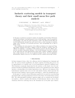
MICROSCOPIA:
come guardare atomi e nanostrutture?
GRAFITE
1cm
Occhio umano
10µm
microscopio ottico
0.1µm
microscopio elettronico
.
0.1nm
1nm
microscopio a scansione
Metodi di scrittura nanoscopica
Metodi di scrittura
nanoscopica:
linguaggio binario
Metodi di scrittura microscopica
Dallo spazio diretto allo spazio reciproco:
lo studio delle strutture ordinate
La diffrazione
di raggi X e
di elettroni
Reticolo di Bravais
Un reticolo di Bravais specifica l’arrangiamento periodico in cui le unità elementari
del cristallo sono disposte.
Tali unità possono essere singoli atomi, gruppi di atomi, molecole, ioni, ecc.
Definizioni:
-Un reticolo di Bravais è una schiera infinita di punti discreti con una disposizione e
un’orientazione che appare la stessa da qualsiasi dei punti la schiera sia vista.
- Un reticolo di Bravais è formato da tutti i punti con vettori posizione della forma:
R = n1a1 + n2 a2 + n3 a3
ai
ni interi
sono detti vettori primitivi
The 14 Bravais Lattices
in 3D
3D crystal structures
CsCl, 2 at/un.cell: (000)a, (1/2,1/2,1/2)a
simple cubic
Li, Na, …, Cr, Nb, V, W, …1 at/un.cell
body centered cubic
Cu, Ag, Au,…, Ni, Pd, … , Ne, Ar, …,1 at/un.cell
NaCl, 2 at/un.cell: (000)a, (1/2,1/2,1/2)a
ZnS 2 fcc : (000)a, (1/4,1/4,1/4)a
face centered cubic
face centered cubic
3D crystal structures
C, Si, Ge 2 fcc : (000)a, (1/4,1/4,1/4)a
GaAs, ZnS 2 fcc : (000)a, (1/4,1/4,1/4)a
a2
φ
a1
Oblique (p) net
|a1|≠|a2| φ≠90°
2D Bravais Nets and
Unit Meshes
Rectangular (c) net
|a1|≠|a2| φ=90°
a1’
a2 φ
a1
Rectangular (p) net
|a1|≠|a2| φ=90°
a2’
φ
a2
φ
a1
Primitive cell
|a1’|≠|a2’| φ≠90°
Unit cell
a1
a2
a2
φ
a1
Square (p) net
|a1|=|a2| φ=90°
φ
Hexagonal (p) net
|a1|=|a2| φ=120°
Cella primitiva di Wigner-Seitz
Cella unitaria è una cella che riempie tutto il
cristallo per operazioni di traslazione,
anche con sovrapposizioni. La cella
primitiva è la più piccola cella unitaria ossia
la cella unitaria di volume minimo. Per
costruzione, contiene un solo punto
reticolare e i soli atomi della base.
Spesso i vettori di traslazione primitivi
vengono usati per definire gli assi
cristallografici, che formano i tre spigoli
adiacenti di un parallelepipedo. A volte
si usano assi non primitivi, quando
sono più convenienti o più semplici.
Reticolo di Bravais in 3D:
celle unitarie convenzionali e celle unitarie primitive
2D Crystallography: 2D Point Groups
SIMMETRIE
TRASLAZIONALE
E ROTAZIONALE
120o
THREE-FOLD
3D reciprocal lattice
In crystallography, the reciprocal lattice of a Bravais lattice is the set of all vectors K
such that
real and
reciprocal
space
Bragg's law (1913):
Interference pattern of X-rays scattered by long
range ordered structures.
n λ =2dsinθ
The path difference is 2dsinθ where θ
is the incidence angle
Von Laue
ei(k’-k)R=1 se k’-k=G
(k’-k)R=2πm
where R is a Bravais lattice vector
PROBE: ions, electrons, neutrons, protons,
with a wavelength comparable to the distance
between the atomic or molecular structures.
http://web.pdx.edu/~pmoeck/phy381/Topic5a-XRD.pdf
Fundamentals of Diffraction Techniques in 3D Space
Diffraction techniques require a long-range translational
symmetry of the system giving access to the reciprocal lattice.
The diffraction process satisfies conservation of energy and
momentum but for the addition of any reciprocal lattice vector.
For a 3D-system:
k = (k )
'
k =k +ghkl
2
' 2
Conservation of Energy
Conservation of Momentum
The diffracted beams are characterized by the points of the
points of the reciprocal lattice.
The wavelength of the projectile particle must be of the same
order of magnitude of the interplanar spacings of the solid.
Fundamentals of Diffraction Techniques
Ewald Sphere Construction in 3D Reciprocal Space
2π 2mE
k= =
λ h2
12
1) A vector k is drawn terminating at the origin of the reciprocal space
2) A sphere of radius k is constructed about the beginning of k
3) For any point at which the sphere passes through a reciprocal lattice point, a line to
this point from the center of the sphere represents a diffracted beam k’
4) Notice the reciprocal lattice vector ghkl
Fundamentals of Diffraction Techniques
k = (k
2
)
' 2
2 2 ' 2 ' 2
k
k
k|| +
k⊥
|| +
⊥=
'
k =k +ghkl
Conservation of Energy
Conservation of Momentum
The indexing of the diffracted beams is, by convention, referenced to
the substrate real and reciprocal net.
.
Collecting Grazing Incidence X-ray Diffraction Data
De
te c
to
r
Z
be
a
m
ω
γ
d
nt be
a
α
m
D
iff
ra
ct
e
Inci
de
I(q)
acted
r
f
f
i
D
be
ion
t
c
e
j
ro
am p
δ
Specular beam
q = kd - ki
'
k =k +ghkl
d
i
Bragg
2dsinθ=nλ
Each sum is peaked at 2np/ai and tends in the limit of large Ni value, to a periodic array
of d-functions with a spacing of 2p/ai.
N 1 q ⋅ R n = 2 nπ
∑n = 0 exp( iq ⋅ ( n1a1 + n2 a 2 + n3a3 ) ) = 0 q ⋅ R ≠ 2nπ
n
1
N1 − 1
The diffracted intensity from a crystal has the special property of being confined along
specific, well-defined directions and is the product of three orthogonal, periodic δ-function
arrays. The momentum transfer q has to simultaneuosly meet the three following conditions
for the intensity to be at the maximum:
q ⋅ a 1 = 2π ⋅ h
q ⋅ a 2 = 2π ⋅ k
q ⋅ a = 2π ⋅ l
3
with h, k and l integer values.
The three conditions can be simultaneously satisfied by Q vectors which represent the
reciprocal lattice points. Since the Q vectors are a set of translation vectors in the reciprocal
space corresponding to the real space crystal structure given by Rn, the Laue condition
simply states that the maximum scattered intensity occurs at the reciprocal lattice points of
the real space crystal structure.
Intensity Distribution
Atoms are never residing at fixed lattice sites, they are thermally vibrating around an
average position. If we include a Debye-Waller factor in the structure factor to consider thermal
N1 − 1 N 2 − 1N 3 − 1
vibrations:
A f = Ae F ( q )
∑
exp( iq ⋅ Rn ) = Ae F ( q ) ∑
∑ ∑
n1 = 0 n2 = 0 n3 = 0
n1,n 2 ,n 3
exp( iq ⋅ ( n1a 1 + n2 a 2 + n3a 3 ) )
where Mj is the Debye Waller factor associated to the j-th atom:
F ( q) =
Nc
∑
j= 1
M j = 8π
f j ( q ) exp( iq ⋅ r j ) exp( − M j )
2
u
2
j
sin θ
sin θ
= Bj 2
2
λ
λ
2
2
Classical approximation: Scattering Amplitude
X-ray scattering cross sections are weak
the intensity of the scattered beam is negligible compared to that of the incident
one.
the incident wave is constant in the whole diffracting volume.
multiple scattering is not considered.
The kinematic approximation of single scattering is valid (1st Born approximation)
Introducing the electron density in the material ρtot(r), the total scattered amplitude for
elastic scattering is given by the coherent addition of the waves scattered by the electrons:
A(q)
q = k d − k i scattering vector,
waves
with
A(q) = ∫ ρ tot ( r ) e − iq.r d 3r
ki and kd wave vectors for the incident and scattered
ki = k d = 2π / λ
ρ tot ( r ) = ∑ ρ j ( r − r j )
The material is a collection of j atoms
at positions rj
j
where ρj(r) is the electron distribution for atom j
A(q) =
∑
j
(
)
− iq.r 3
ρ
r
−
r
e
d r=
j
j
∫
∑
j
− iq.u 3
(
)
ρ
u
e
d ue
j
∫
− iq.r j
=
∑
fj e
− iq.r j
j
Introducing the atomic form factor :
f j0 ( q ) =
− i q .u 3
(
)
ρ
u
e
d u
∫ j
|q|
I(q)
Strategy
I (hkl )
∝
F hkl
2
∆qFWHM=2/Lc
Lc =2/ ∆qFWHM
Measuring the peak maximum is not reliable
De
te c
to
r
One measures the integrated intensity by
Rocking the sample in front of the detector
Z
ω
α
γ
δ
q D =2π/∆qFWHM = πLc
Requirements for a good data set
Diffractometer degrees of freedom
grazing angle α
sample rotation axis ω
Detector in-plane rotation δ
Detector out of plane rotation γ
Accurate data normalization
Instrument resolution function
Sample size effects
DE BROGLIE
c
E = hν = h
λ
c
E = hν = h
λ
h
λ =
mv
DAVISSON E GERMER
Le particelle si comportano come onde
con λ=h/mv e vengono diffratte
hk2/2m
electrons
Sonda
e- lento
Massa (g)
9 x 10-28
Velocità (m/s)
1.0
λ (m)
7 x 10⁻⁴
e- veloce
9 x 10-28
5.9 x 10⁶
1 x10⁻¹⁰
Inelastic Mean Free Path (nm)
10
Inelastic Mean Free Path
of Electrons vs. Kinetic
Energy
5
1.0
0.5
50 100 500 1000 5000 1000
Kinetic Energy (eV)
The inelastic mean free path of excited electrons in
solids is very short with respect to the inter-atomic
distance.
How the emission of
elastically scattered
electrons decays as a
function of depth (z)
Excited Electron
Solid Surface
θ
0
1-st
z3
2-nd
3-rd
4-th
5-th
z
Excited Atom
Solid
Fundamentals of Diffraction Techniques
Ewald Sphere Construction in 2D Reciprocal Space
Notice that the
reciprocal lattice is now
replaced by infinite
reciprocal lattice rods
perpendicular to the
surface and passing
through the reciprocal
net points
1)
At surfaces 2D translational symmetry holds thereby only the wave vector
parallel to the surface is conserved with the addition of a reciprocal net
vector
2) The procedure of Ewald sphere construction is similar to the 3D case
3) The dashed scattered wave vectors propagate into the solid and are not
observable
Fundamentals of Diffraction Techniques in 2D Space
k = (k )
2 2 ' 2 ' 2
k
k
k|| +
k⊥
|| +
⊥=
Conservation of Energy
'
k || =k|| +ghk
Conservation of Momentum
2
k⊥
' 2
is not conserved since the translational
symmetry normal to the surface is now broken
The indexing of the diffracted beams is, by convention, referenced to
the substrate real and reciprocal net.
If the selvedge or adsorbate structures have larger periodicities, the
surface reciprocal net is smaller than that of the substrate alone.
The extra reciprocal net points and associated diffracted beams are
dnoted by fractional rather than integral indices.
LEED: How the Surface Meshes in the Real Space and in
the Reciprocal Space Correspond Each Other
Laue Conditions
a1 • (s - s0) = n1 λ
a2 • (s - s0) = n2 λ
s00
s0
s01
a1
a2
b1
b2
s11
s01
∆ s / λ = n 1 b1 + n2 b2
(ai • bj = δij)
LEED: A Series of Observations
To a first approximation, the single scattering formalism (kinematical
approximation) is adopted.
The incident electron is described as a plane wave and the amplitude
of the outgoing electron is given by the coherent sum of scattering
from each atom
A
e
x
p
i∆
k⋅A
fj e
x
p
i∆
k⋅r
(
)
(
∑
∑
∑
∆
k=
j)
n m
A ∆k
A
fj
rj
j
Amplitude of the outgoing electron
Real surface net vector
Atomic scattering factor
Position vector within a surface unit mesh
n, m Indices of surface meshes
LEED: A Series of Observations
1) The atomic scattering cross section (fj) involves a phase shift (also
dependent on k) and is thus complex
2) the incident wave is exponentially attenuated in the solid
3) Since atom-electron scattering cross sections can be very large (≈
1 Å2, i.e. 1010 times larger than in X-ray diffraction), multiple
scattering must be included. This means that each incident electron is
treated a a superposition of the primary wave and the scattered
waves
A
expi
k⋅A
F
(∆
)
∑
∑
∆
k=
∆
k
n m
F∆k =∑
fj expi∆
(k⋅rj )
j
Geometrical structure factor
Calculated Diffraction Intensities
Spot Separation Halfwidth
(relative to 2π/a)
One atom
∞
∞
Two atoms
(distance a)
1
1/2
1
1/N
N atoms in a row
(regular distance a)
Several (M) groups of N atoms
each (regularly spaced)
[distance of group centers
(N+1/2)a]
Several groups of varying size
(arranged as in (d))
N atoms randomly distributed
over 2N regular sites
1/[N+(1/2)]
1/{M[N+(1/2)]}
1
dependening on
spot size and
mixture
1
1/(2N)
Real Space
Reciprocal Space
Si(111)(7x7)
Examples of LEED Patterns
(a) Si(111) (7x7)
(b) GaAs(110)
(c) Sr2CuO2Cl2
Notice that the LEED spots span
a variety of relative intensities
Examples of LEED Patterns
) Si(111) (7x7)
) Si(111) (5x5)
Examples of LEED Patterns
local order by STM
c(2x6) K-InAs(110)
long-range order
by LEED
GRAFENE: Super-reticoli in 2D
Dalle dimensioni del cristallo….
….alla fase amorfa
Dal solido al liquido
A(q) =
∑ ∫ ρ j ( r − r j )e
j
− iq.r 3
d r=
∑ ∫ ρ j ( u) e
j
− iq.u 3
d ue
− iq.r j
=
∑
j
fj e
− iq.r j
Dal solido al liquido
A(q) =
∑ ∫ ρ j ( r − r j )e
j
− iq.r 3
d r=
∑ ∫ ρ j ( u) e
j
− iq.u 3
d ue
− iq.r j
=
∑
j
fj e
− iq.r j
Da sistemi “semplici”a sistemi “complessi”
© Copyright 2026 Paperzz