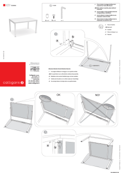
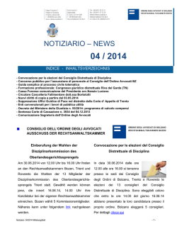
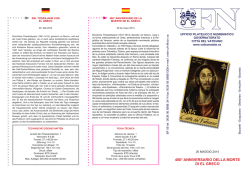
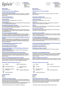
D12
D120IB201
( berenice )
Luceplan Spa
Via E.T. Moneta 40
20161 Milano
Italia
T +39 02662421
F +39 0266203400
[email protected]
www.luceplan.com
design
alberto meda - paolo rizzatto
INDICE
INDEX
02
Descrizione / Description
Beschreibung / Description / Descripción
INHALT
INDEX
10
3- Inserimento vetro di protezione UV
3- Inserting the UV protection glass
3- Einsetzen des UV Schutzglases
3- Pour introduire le verre de protection UV
11
4- Inserimento riflettore
4- Inserting the reflector
4- Einsetzen des Reflektors
4- Pour introduire le reflecteur
12
5- Perno di sicurezza
5- Safety distance rod
5- Sicherheit-Distanzstück
5- Pivot de surete
13
6- Sostituzione del riflettore
6- Substituting reflector
6- Auswechseln des reflektors
6- Pour remplacer le reflecteur
Modelli / Models / Ausführungen / Modèles
Accessori separati / Separate accessories
Separates Zubehör / Accessoires separes
03
Modelli / Models / Modelle / Modeles
D12 El / D12 El pi
base / base /standfuß / base
04
D12 El pt
perno tavolo / table pivot / Stift-Befestigung /
pivot pour table
D12 El a 45 / D12 El a pi
parete / wall / wand / applique
05
D12 El t
terra / floor / boden / de soil
06
Accessori / Accessorie / Zubehöre / Accessoires
7- Sostituzione della lampadina e del vetro di protezione
7- Replacing the lamp and the protection glass
7- Auswechseln des Leucht mittels und des schutzglases
7- Remplacement de l’ampoule et du verre de protection
14
D12 / 1 base / D12 / 1 base / D12 / 1 standfuß / D12 / 1 base
07
D 12 / 75 Perno tavolo / D 12 / 75 Table pivot
D 12 / 75 Stift für Tisch / D 12 / 75 Pivot pour table
9- Registrazione delle frizioni
9- Adjusting the frictions
9- Justieren der Gelenke
9- Reglage des frictions
D 12 / 3 Attacco a parete / D 12 / 3 Wall attachment
D 12 / 3 Wandbefestigung / D 12 / 3 Applique
08
Montaggio / Assembly / Montage / Montag
15
1- Inserimento nel supporto
1- Mounting on support
1- Einsetzen in den Halter
1- Introduction dans les support
09
2- Connessione al trasformatore
2- Connection to the transformer
2- Anschluß an den Transformator
2- Raccordement au transformateur
8- Orientamento della testa
8- Orienting the head
8- Orientieren des Kopfes
8- Orientation de la tête
10- Contatti elettrici
10- Electrical contacts
10- Elektrische Verbindungen
10- Contacts electriques
11- Lubrificazione
11- Lubrification
11- Schmierung
11- Lubrification
16
ATTENZIONE / WARNING
ACHTUNG / ATTENTION / ADVERTENCIA
01
D12 El pi
L cm 30 + 30
D12 El pt
L cm 45 + 45
A series of lamps articulated and balanced for 35W 12V
halogen bulb. Available in the table, floor and wall version.
Metallic parts in pressure-casting of aluminium in black
or silver aluminium finishes; adjustable hinges in
reinforced nylon and support ring of the reflector in
aluminium or in pressed glass. 230 or 120/12V transformer on the wire; switch on the head hinge.
D12 El a 45
L cm 45 + 45
D12 El a pi
L cm 30 + 30
D12 El t
L cm 80 + 30
Eine Reihe balancierter Gelenkleuchten für 35W / 12V
-Halogenlampe. Lieferbar als Tisch-, Steh- und Wandleuchte. Metallteile aus Aluminiumpressguß in schwarz
oder Naturaluminium; verstellbare Gelenke aus
verstärktem Nylon und Reflektorstützring aus Rynite;
Parabolischer-Reflektor as Aluminium oder Pressglas.
230 oder 129/12V- Transformator auf dem Kabel;
Schalter am Kopfgelenk.
Accessori separati
Separate accessories
Separates Zubehör
Accessoires separes
Série de lampes articulées et équilibrées pour ampoule
alogéne 35W 12V. Disponible dans la version de table, sur
pied et applique. Parties métalliques en moulées sous
pression en aluminium dans les finitions noir ou
aluminium naturel; roules réglables en nylon renforcé et
bague de support du reflecteur en rynite; reflecteur
parabolique en aluminium ou en verre pressé.
Transformateur 230 ou 120/12 Volt sur le fil; interrupteur
sur la roule de la tête.
D12 / 1
02
cm
80°
40°
45 cm
L cm 45 + 45
45
30
cm
80°
40°
7,5 cm
D12 El
Modelli
Models
Modelle
Modeles
7,5 cm
Serie di lampade articolate ed equilibrate per lampadina
alogena 35W, 12V. Disponibile nelle versioni tavolo, terra e
parete. Parti metalliche in pressofusione di alluminio
nelle finiture nero o argento; snodi regolabili in nylon
rinforzato e anello di sostegno del riflettore in rynite;
riflettore parabolico in alluminio o vetro pressato.
Trasformatore 230 o 120/12 Volt sul filo; interruttore sullo
snodo della testa.
D12 El / D12 El pi
base / base /standfuß / base
Modelli
Models
Ausführungen
Modèles
30 cm
Descrizione
Description
Beschreibung
Description
Base / Base /Standfuß / Base
D12 / 75 Perno tavolo / Table pivot
D12 / 3
Con il tratteggio sono indicate le posizioni limite.
Stift für Tisch / Pivot pour table
Broken line indicates maximum extension.
Attacco a parete / Wall attachment
Grezpositionen werden mit Schraffierungen bezeichnet.
Wand-Befestigung / Applique
Les positions limite sont indiquées par la hachure.
03
D12 EL pt
perno tavolo / table pivot / Stift-Befestigung /
pivot pour table
45
D12 El a 45 / D12 El a pi
parete / wall / wand / applique
D12 El t
terra / floor / boden / de soil
cm
c
45
m
45
cm
80°
cm
12 cm
45
30
cm
80°
30
80 cm
30
cm
cm
7,5
30° 30°
04
05
Accessori
Accessorie
Zubehöre
Accessoires
Ø 13.5mm
La base viene utilizzata sia nella versione da tavolo
che nella versione da terra.
La scanalatura serve per il passaggio del cavo elettrico.
The base is the same for table and floor models.
Groove is for the electric chord.
Der Standfuß wird für das Tisch- und BodenModell verwendet.
Die Nute ist zur Fuhrung der elektrischen Leitung
vorgesehen.
La base est utiliséè aussi bien dans la versione de
table que dans la versione de sol.
La rainure sert pour la passage du câble
électrique.
06
D 12 / 3 Attacco a parete
D 12 / 3 Wall attachment
D 12 / 3 Wand-Befestigung
D 12 / 3 Applique
D12 / 75 Perno tavolo
D12 / 75 Table pivot
D12 / 75 Stift für Tisch
D12 / 75 Pivot pour table
max. 57mm
D12 / 1 Base
D12 / 1 Base
D12 / 1 Standfuß
D12 / 1 Base
Preparare un foro da 14mm nel piano. Inserire il
perno nel foro e fissarlo con il dado, assicurandosi di
interporre la rondella.
Make a 14mm hole in the plate. Place the table pin in
the 14 mm hole and fix it with the washer and nut.
Ein 14mm-Loch in der Platte vorbereiten. Den Stift in
das Loch einfügen und ihn mit Unterlegscheibe und
Mutter befestigen.
Préparer un trou de 14 mm dans le plan. Insérer le
pivot dans le trou et fixer avec l’écrou en s’assurant
de bien intercaler la rondelle.
Il supporto per fissaggio a parete è corredato di due
tasselli per il fissaggio a muro. Il foro di innesto deve
essere rivolto verso l'alto.
The wall mount comes with two expansion plugs for
the wall attachment. The hole for coupling must be
turned upward.
Dem Halter dieses Modells sind zwei Dübel beigelegt,
welche die Befestigung an die Wand ermöglichen. Das
Einfügungloch muss nach oben gerichtet werden.
Le support pour le fixage au mur est muni de deux
goujons pour le fixage de la applique. Le trou
d'introduction doit être tourné vers le haut.
07
2- Connessione al trasformatore
2- Connection to the transformer
2- Anschluß an den Transformator
2- Raccordement au transformateur
1- Inserimento nel supporto
1- Mounting on support
1- Einsetzen in den Halter
1- Introduction dans les support
Montaggio
Assembly
Montage
Montag
a
b
08
c
Impugnare, escludendo il tirante, le due astine.
Inserire il perno (a) nel supporto facendo scorrere il
grano sporgente (b) nella scanalatura verticale.
ATTENZIONE: la lampada non può ruotare se il perno (a)
non è infilato sino a che il blocchetto (c) sia a contatto
con il supporto.
Connettere la lampada al trasformatore in dotazione
attraverso lo spinotto.
Output del trasformatore: 24 Vcc, min. 500 mA.
Hold lamp as shown without grasping the tie rod and
slip pivot (a) into the support, aligning the guide (b)
with the vertical groove.
ATTENTION: lamp will not rotate until pivot (a) is not
inserted all the way so that stop (c) touches the
support.
Connect the lamp to the transformer through the
connector.
Output of the transformer: 24 Vcc, min. 500 mA.
Das Gerät an den zwei Stäben, jedoch nicht am
Zugglied, greifen, den Bolzen (a) in den Halter
einführen, dabei muss der Führungsstift (b) in die
senkrechte Nute gleiten.
ACHTUNG: Solange der Bolzen (a) nicht so tief in den
Halter eingeschoben wird, dass die Nase (c) mit der
Oberkannte des Halters bündig abschiesst, lässt sich
die Leuchte nicht drehen.
Die Leuchte an den mitgelieferten Transformator
durch den Stecker verbinden.
Ausgang des Transformators: 24 Vcc, min. 500 mA.
Saisir, en escluant le tirant, les deux petites tiges.
Introduire le pivot (a) dans le support en faisant glisser la
vis sans tête qui dépasse (b) dans la rainure verticale.
ATTENTION: la lampe ne peut pas tourner si le pivot (a)
n’est pas nefilé jusqu’a ce que le petit bloc d’arrêt (c) soit
en contâct avec le support.
Connecter la lampe au transformateur fourni avec la
broche.
Output du transformateur: 24 Vcc, min. 500 mA.
09
4- Inserimento riflettore
4- Inserting the reflector
4- Einsetzen des Reflektors
4- Pour introduire le reflecteur
3- Inserimento vetro di protezione UV
3- Inserting the UV protection glass
3- Einsetzen des UV Schutzglases
3- Pour introduire le verre de protection UV
d
e
Inserire preliminarmente la lampadina nel portalampada. Infilare il vetro di protezione UV appoggiandolo
all’interno dell’anello.
Insert the lamp into the lamp holder. Insert the UV
protection glass so that the teeth of the metal ring rest
on the inside edge of the plastic ring.
Zunächst das Leuchtmittel in die Lampenfassung
einsetzen. Dann das UV Schutzglas einführen, indem
die Zähnchen der Metallumrandung auf den inneren
Rand des Ringes aufgelegt werden.
Introduire premièrement l’ampoule dans la douille.
Ensuite, enfiler le verre de protection UV en ayant soin
de poser les petites dents de l’embout métallique sur
le bord interne de l’anneau.
10
Assicurarsi che i quattro dentini della ghiera mettallica
appoggino perfettamente in piano.
Make sure that all four teeth of the metal ring are in
the flat position.
Bitte beachten Sie, daß alle vier Zähnchen der
Metallumrandung einwandfrei aufliegen müssen.
S’assurer que les quatre petites dens de l’embout
métallique soient parfaitement posées à plat.
Prendendo con entrambe le mani il riflettore e, tenendo
fermo l’anello, inserirlo nei dentini posteriori (d) come
indicato dalle frecce.
Inserire il riflettore nel dentino anteriore (e) dell’ anello
esercitando con i pollici una leggera pressione verso il
basso fino al “clac”.
Take the reflector with both hands and holding the
plastic ring insert the edge of the reflector under the
two rear teeth (d) as shown by the arrows.
Then insert the reflector under the front tuuth (e) of the
ring pressing slightly until it snaps in.
Some expansion pressure on the plastic ring would ease
the snap in action. Excessive force may cause breakage.
Nehmen Sie den Refektor in beide Hände und führen
Sie ihn, bei gleichzeitigem Festhalten des Ringes,
unter die beiden hinteren Sperrzähne (d) des
Ringes in Pfeilrichtung ein.
Prendre à deux mains le réflecteur et en tenant fixe
l’anneau, introduiser-le dans les petites dents
postérieures (d) comme indiquent les flèches.
Der Rrflektor wird unter den vorderen Sperrzahn (e) des
Ringes eingeführt, indem mit den Daumen ein leichter
Druck nach unten ausgeübt wird, bis der Reflektor
einrastet.
Introduire le réflecteur dans la petite dent antérieure (e)
de l’anneau en exerçant avec les pouces une légère
pression vers le bas jusqu’au “clac”.
11
6- Sostituzione del riflettore
6- Substituting reflector
6- Auswechseln des reflektors
6- Pour remplacer le reflecteur
5- Perno di sicurezza
5- Safety distance rod
5- Sicherheit-Distanzstück
5- Pivot de surete
7- Sostituzione della lampadina e del vetro di protezione
7- Replacing the lamp and the protection glass
7- Auswechseln des Leucht mittels und des schutzglases
7- Remplacement de l’ampoule et du verre de protection
Manutenzione
Maintainance
Leuchtenpfleg
Entretien
g
f
e
Per impedire che la lampadina sia inavvertitamente
lasciata a contatto con superfici infiammabili utilizzare
il perno (f), avvitandolo nei fori (g) come indicato.
To avoid accidental contact of the halogen bulb with
flammable surfaces insert small distance rod (f) and
screw it into the holes (g) as indicated.
Per togliere il riflettore fare leva con un cacciavite tra il
riflettore e l’anello agendo vicino al dentino anteriore (e).
Prima di procedere assicurarsi che il riflettore sia freddo.
To remove the reflactor, put the tip of a screwdriver
between the reflector and the ring, and pry on the front
tooth (e).
Make sure the reflector is cool before removing it.
Das Sicherheit_Distanzstück (f) verhindert, daß die
Halogenlampe in Berührung mit zündfähigen
Oberrflächen versehentlich kommt.
In den Bohrungen (g) wie angegeben einschrauben.
Der Reflektor wird herausgenommen, indem man einen
Schraubenzieher zwischen den Reflektor und den Ring in
die Nähe des Sperrzahnes (e) einführt und ihn als Hebel
agieren läßt.
Bitte achten sie unbedingt darauf, dass der refektor nur
in abgekühltem zustand herausgenommem werden soll.
Pour empêcher que l’ampoule soit mis en contact par
inadvertance avec des surfaces inflammables, utiliser
le pivot (f) et le visser dans les foreaux (g) comme
indiqué.
Pour ôter le réflecteur, avec un tourne-vis faire levier sur
le réflecteur et l’anneau en agissant près de la petite dent
antérieure (e).
Avant de proceder, s’assurer que le reflecteur soit froid.
12
Per il ricambio della lampadina e del vetro di protezione
togliere innanzitutto il riflettore come indicato al punto 5 e
procedere come indicato al punto 2.
To replace the lamp and the protection glass, remove first
of all the reflactor as shown in step 5, then follow step 2.
Um das Leuchtmittel und das Schutzglas auszuwechseln muß zunächst wie unter Punkt 5 beschrieben der
Reflektor herausgenommen werden Verfahren Sie
danach bitte wie unter Punkt 2 beschrieben.
Pour remplacer l’ampoule et le verre de protection,
ôter avant tout le réflecteur comme indiqué au point 5
et procéder suivant le point 2.
13
8- Orientamento della testa
8- Orienting the head
8- Orientieren des Kopfes
8- Orientation de la tête
9- Registrazione delle frizioni
9- Adjusting the frictions
9- Justieren der Gelenke
9- Reglage des frictions
10- Contatti elettrici
10- Electrical contacts
10- Elektrische Verbindungen
10- Contacts electriques
2
2
3
1
11- Lubrificazione
11- Lubrification
11- Schmierung
11- Lubrification
1
2
3
3
Per orientare il riflettore senza scottarsi manovrare
con l’astina distanziale.
To orient the reflector without burning, operate the
distance rod.
Um den Reflektor zu orientieren, ohne sich zu
verbrennen, den Distanzstab zu handeln.
Pour orienter le réflecteur, sans se brûler,
manoeuvrer avec le levier de distance.
14
Per regolare l'equilibrio meccanico del braccio agire
sugli appositi dadi di nylon 1,2,3 mediante l'utilizzo di
una monetina.
ATTENZIONE: i contatti elettrici dipendono dalla corretta
tenuta dei dadi in nylon 1,2,3. Un eccessivo allentamento
può rendere instabile l'accensione della lampadina.
The mechanical balance of the arm is adjusted by
tightening the nylon nuts 1,2,3 by means of a coin.
ATTENTION: electrical contacts depend on the proper
tightening of the nylon nuts 1,2,3. If they are too loose bulb
may behave erratically.
Zur Justierung des mechanischen Gleichgewichts des
Armes die Sondermuttern aus Nylon 1,2,3 mit einer
Münze einstellen.
Pour régler l'équilibre du bras, agir sur les écrous en
nylon 1,2,3 à l'aide d'une piéce de monnaie.
ACHTUNG: Die elektrische Verbindung hängt von der
richtigen Blockierung durch die Sondermuttern 1,2,3 ab.
Eine aussergewöhnlich starke Lockerung kann das
Funktionieren der Lampe beeinträchtigen.
ATTENTION: les contacts électriques dépendent de la
tenue correcte des "petits écrous" 1,2,3. Un desserrage
excessif peut tendre instable l'allumage de l’ampoule.
Per garantire l'efficienza della lampadina tutte le
superfici dei contatti sono lubrificate con speciale
grasso conduttore, che non va tolto. Lubrificare
periodicamente.
For the perfect efficiency of the halogen bulb, contact
surfaces are lubricated with special conductor grease
that must not be removed. Lubricate periodically.
Zur Erhaltung der Halogenbirne sind alle Kontaktoberfläche durch Sonderleiter-Schmierfett geschützt,
welches nicht entfernt werden darf. Regelmässig
wiederschmieren.
Pour le rendement maximum de l'ampoule, les
surfaces de contact seront lubrifiées avec une graisse
conductrice spéciale, qui ne doit pas être enlevée.
Relubrifier périodiquement.
15
!
ATTENZIONE
WARNING
LA SICUREZZA DELL'APPARECCHIO E' GARANTITA SOLO
RISPETTANDO QUESTE ISTRUZIONI, SIA IN FASE DI
INSTALLAZIONE CHE DI IMPIEGO; E' NECESSARIO
CONSERVARLE. IL PRODUTTORE NON RISPONDE DI DANNI
DERIVANTI DA UN USO SCORRETTO DELL'APPARECCHIO.
Dopo aver tolto l'imballaggio, assicurarsi dell'integrità
dell'apparecchio. Gli elementi dell'imballaggio (sacchetti in plastica,
polistirolo espanso, graffette) non devono essere lasciati
alla portata dei bambini, in quanto potenziali fonti di pericolo.
Non utilizzare l'apparecchio se danneggiato.
Questo apparecchio dovrà essere destinato solo all'uso
per il quale è stato espressamente concepito.
Il costruttore non può essere considerato responsabile di
eventuali danni derivati da usi impropri, erronei e irragionevoli.
Prima di collegare l'apparecchio accertarsi che i dati di targa
siano rispondenti a quelli della rete di distribuzione.
INSTALLAZIONEAll'atto dell'installazione e ogni qual volta si
intervenga sull'apparecchio, assicurarsi che sia stata tolta la
tensione di alimentazione!
Apparecchio adatto per montaggio su superfici
F
normalmente infiammabili.
MANUTENZIONE E SOSTITUZIONE LAMPADINEUtilizzare
esclusivamente il tipo di lampadina indicato, non superare mai
la potenza massima stabilita. Se il cavo di questo apparecchio
viene danneggiato deve essere sostituito esclusivamente
da personale qualificato e autorizzato dal costruttore
dell'apparecchio utilizzando il ricambio originale.
Utilizzare esclusivamente lampadine che non
necessitano di schermo di protezione.
PULIZIA APPARECCHIO/PARALUME
Per la pulizia del diffusore dalla polvere utilizzare un pennello
morbido e asciutto.
Se dopo aver letto queste istruzioni rimangono dei dubbi
contattare il rivenditore prima di montare l'apparecchio.
16
!
SAFETY OF THIS APPLIANCE IS GUARANTEED ONLY IF THESE
INSTRUCTIONS ARE ABIDED, IN THE PHASE OF
INSTALLATION OR USE; IT IS NECESSARY TO KEEP THEM.
THE MANUFACTURER IS NOT LIABLE FOR DAMAGES DERIVED
FROM AN INCORRECT USE OF THE APPLIANCE.
After unpacking the appliance, be sure it has not been damaged.
The packing components (plastic bags, expanded polystyrene,
paper clips) must be kept out of reach of children, as they are
potentially dangerous. Do not use the appliance if damaged.
This appliance must be intended to be used only for what
is has been designed. The manufacturer is not liable
for eventual damage due to misuse, incorrect or inadequate use.
Before connecting the appliance, be sure the voltage rate
correspond to those of the distribution network.
INSTALLATION
Upon installation and any intervention on the appliance, check
the power supply voltage is off!
This appliance is suitable for assembling on normally
F
flammable surfaces.
MAINTENANCE AND LIGHT BULB REPLACEMENT
Use only the indicated light bulb type, do not exceed the preset
maximum output. If the cable of the appliance is damaged it
must be replaced only by qualified personnel, authorized by the
appliance manufacturer, using the original spare parts.
Use only light bulbs that do not need a protectionscreen.
APPLIANCE/LAMPSHADE CLEANING
To clean the body use a dry soft brush.
If after reading these instructions there is any doubt, contact
the retailer before assembling the appliance.
ACHTUNG
ATTENTION
DIE GERÄTESICHERHEIT IST NUR DANN GEWÄHRLEISTET, WENN
SIE DIESE INSTALLATIONS- UND BEDIENUNGSANLEITUNG
BERÜCKSICHTIGEN; BEWAHREN SIE DIE ANLEITUNG AUF. DER
HERSTELLER ÜBERNIMMT KEINE HAFTUNG BEI
UNSACHGEMÄSSER VERWENDUNG DES GERÄTS.
Überprüfen Sie nach dem Auspacken, ob das Gerät
unbeschädigt ist. Die Verpackung (Plastiktüten, Schaumstoff,
Klammern) dürfen nicht in Kinderhände geraten, da sie
mögliche Gefahrenquellen darstellen. Das Gerät nicht
verwenden, wenn es beschädigt ist. Dieses Gerät darf nur für
den vorgesehenen Einsatzzweck verwendet werden. Der
Hersteller haftet nicht bei Schäden, die auf unsachgemäßen,
falschen oder unvernünftigen Gebrauch zurückzuführen sind.
Vergleichen Sie die Daten auf dem Typenschild mit dem
vorhandenen Stromnetz, bevor Sie das Gerät anschließen.
INSTALLATION
Stellen Sie sicher, dass die Stromverbindung unterbrochen ist,
bevor das Gerät installiert oder gewartet wird!
Das Gerät ist zur Montage auf normal brennbaren
F
Flächen geeignet.
WARTUNG UND AUSTAUSCH DES LEUCHTMITTELS
Verwenden Sie ausschließlich den angegebenen Leuchtmitteltyp
und überschreiten Sie niemals die angegebene Maximalleistung.
Falls das Kabel des Geräts beschädigt ist, muss es durch einen
vom Hersteller autorisierten Fachmann mit Original-Ersatzteilen
ausgetauscht werden.
Verwenden Sie nur Leuchtmittel, die keine
Schutzscheibe benötigen.
REINIGUNG GERÄT/LAMPENSCHIRM
Für die Reiniging des Gehäuses einen weichen trockenen Pinsel
benutzen.
Falls Sie nach der Lektüre dieser Anleitung weitere Fragen
haben sollten, wenden Sie sich bitte an den Händler, bevor Sie
das Gerät montieren.
LA SÉCURITÉ DE L’APPAREIL N’EST GARANTIE QUE SI CES
INSTRUCTIONS SONT RESPECTÉES, AUSSI BIEN LORS DE
L’INSTALLATION QUE DE L’UTILISATION; IL FAUT DONC LES
CONSERVER. LE FABRICANT NE RÉPOND PAS DE DOMMAGES
DÉRIVÉS D’UNE UTILISATION INCORRECTE DE L'APPAREIL.
Après avoir déballé l’appareil, s’assurer de son intégrité. Les
éléments d'emballage (sacs en plastique, polystyrène expansé,
agrafes) ne doivent pas être laissés à la portée des enfants,
puisqu’ils constituent de sources potentielles de danger. Ne
pas utiliser l’appareil s’il est endommagé. Cet appareil ne devra
être destiné qu’à l’utilisation pour laquelle il a été
expressément conçu. Le fabricant ne peut pas être tenu
responsable de dommages éventuels dérivés d’utilisations
impropres, incorrectes ou insensées. Avant de brancher
l’appareil, s’assurer que les données de la plaque signalétique
correspondent à celles du secteur.
INSTALLATION
Lors de l’installation et à chaque intervention sur l’appareil, s’assurer
que la tension d’alimentation a été coupé!
F Appareil apte au montage sur des surfaces
normalement inflammables.
ENTRETIEN ET REMPLACEMENT DES AMPOULES
Utiliser exclusivement le type d’ampoule indiqué, ne jamais
dépasser la puissance maximum établie. Si le câble de cet
appareil est endommagé, il doit être remplacé exclusivement
par du personnel qualifié et autorisé par le fabricant de
l'appareil, en utilisant une pièce de rechange d’origine.
Utiliser exclusivement des ampoules ne nécessitant pas
d’écran de protection.
NETTOYAGE DE L’APPAREIL/ABAT-JOUR
Pour le nettoyage du diffuseur utiliser un pinceau souple et sec.
Si après avoir lu ces instructions il en reste des doutes,
contacter le revendeur avant de monter l’appareil.
17
© Copyright 2026 Paperzz