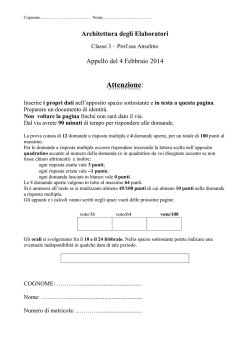
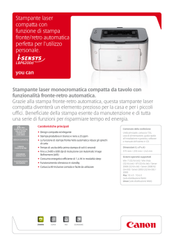
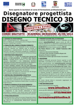
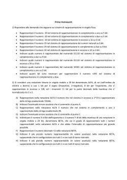
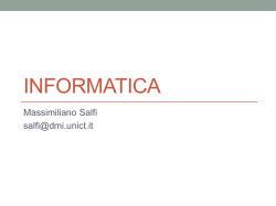
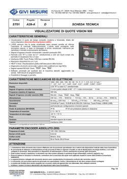
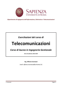
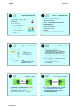
Interfaccia Seriale Sincrona SSI
Synchronous Serial Interface
AZIENDA CON SISTEMA QUALITA’ CERTIFICATO IN CONFORMITA’ ALLA NORMA UNI EN ISO 9001:2008
COMPANY WITH QUALITY SYSTEM CERTIFIED ACCORDING TO UNI EN ISO 9001: 2008
CARATTERISTICHE GENERALI
GENERAL CHARACTERISTICS
ORIGINE DELL’INTERFACCIA “SSI”
“SSI” INTERFACE ORIGIN
L’evoluzione tecnologica che intressa le applicazioni relative alle macchine a controllo numerico, ha
portato alla richiesta di sempre maggiore precisione nel rilevamento della posizione di alberi rotanti,
sviluppati anche su di un elevato numero di giri. Questa aspettativa è stata soddisfatta, dai costruttori
di encoders, con un incremento della risoluzione di misura disponibile sui modelli assoluti mono e
multigiro. Il mondo dell’industria si è quindi trovato a disporre di strumenti di elevata precisione,
pienamente adeguati alle necessità di misura, ma con l’incoveniente dell’elevato numero di
connessioni da effettuare per il collegamento dell’encoder al sistema di controllo (la Italsensor
fabbrica encoders assoluti multigiro con risoluzioni fino a 8192 passi per giro x 4096 giri che
forniscono in uscita 25 bit di segnale, ai quali debbono corrispondere altrettanti conduttori integrati
con alimentazione e segnali di I/O opzionali). Per cercare di ridurre i costi di installazione e
semplificare i collegamenti è nata un’interfaccia seriale sincrona (Syncronus Serial Interface),
meglio conosciuta come SSI, verso la quale l’industria sta guardando con sempre maggiore
interesse.
The technological evolution hat concern the applications related to the numerical controlled
machines has generated a request for always more precision of acquirement of the position of the
rotating shafts also for high number of turns. This requirement has been satisfied by encoder
manufacturers, with an increment of measuring resolution available on single- and multiturn absolute
encoders. Industry has got therefore very high precision instruments, fully suitable for the measuring
needs but with the inconvenient of the high number of connections to be made for the connection for
the encoder to the control system. (Italsensor is manufacturing multiturn encoders with resolutions up
to 8192 steps per turn x 4096 turns which supply on output 25 signal bit, to which same quantity of
integrated conductors with power supply and input and output optional signals must correspond .
In order to reduce the installation costs and in order to simplify the connections the synchronus
serial interface , better know as SSI, has been developed and is catching always higher interest
from industry.
VANTAGGI DI UTILIZZO DELLA “SSI”
ADVANTAGES OF “SSI” APPLICATION
L’utilizzo della SSI ha presentato
immediatamente una serie di vantaggi per
l’utilizzatore, quali:
! semplificazione del cablaggio con utilizzo
di soli 6 conduttori schermati, qualunque
sia la risoluzione richiesta;
! possibilità aggiornamento della
risoluzione di un impianto esistente senza
onerose modifiche di cablaggio;
! sicurezza del codice trasmesso in formato
Gray;
! estrema semplicità ed economicità di
realizzazione della conversione del
codice da Gray a Binario (vedi pag. 14);
! possibilità di adattare al velocità di
trasmissione dell’encoder in funzione
della distanza di trasmissione;
! ulteriore riduzione del numero di
connessioni grazie alla possibilità di
utilizzare un unico CLOCK (2 conduttori)
per un gruppo di encoders che
trasmettono ciascuno su di un proprio
doppino;
! determinazione della tempistica e della
velocità di trasmissione direttamente da
parte del controllo.
The SSI application has immediately given
advantages for the user such as:
! easier wiring with the use of only 6 screened
conductors for any possible resolution
request
! possibility to update of the resolution of an
existing machinery without expensive wiring
modifications
! reliability of the code with Gray format
! extreme simplicity and low cost for the
conversion of the Gray code into Binary
(please refer to page 14)
! possibility to adapt the encoder transmission
speed depending from the transmission
distance
! further reduction of the connections quantity
thanks to the possibility to use only one
CLOCK (2 conducers) for a group of
encoders each of which transmits on his own
double wire
possibility to determine the time and the
transmission speed directly from the control
board.
PRINCIPIO DI FUNZIONAMENTO
FUNCIONING PRINCIPALS
Il sistema ottico di lettura del codice, comprendente uno o più dischi codificati, rende disponibili
costantemente i valori aggiornati della posizione rilevata. Il codice così generato viene presentato
all’ingresso di un convertitore parallelo/seriale (P/S) controllato in modo sincrono da una frequenza di
clock ricevuta sugli ingressi CKI e CKI (figura pagina precedente )
Tali segnali assumono a riposo il valore logico “1” o “HIGH”; il controllo interroga l’encoder circa la sua
posizione inviando un treno di impulsi di clock, il cui numero è funzione del numero di bit che devono
essere trasmessi (risoluzione dell’encoder) ed al protocollo di trasmissione attivato. Alla prima
transizione “HIGH-LOW” il dato presente all’ingresso del convertitore P/S viene da questo
memorizzato; la successiva transizione “LOW-HIGH” presenta, all’uscita del convertitore P/S, il dato
relativo al MSB. Ogni successiva transizione “LOW-HIGH” del treno di impulsi determina la
presentazione sulla linea OUT del bit successivo. Esaurita la sequenza di impulsi stabilita dal
protocollo utilizzato, e dopo un tempo minimo pari a 1/2 impulso di clock l’uscita ritorna in stato di
riposo, consentendo l’aggiornamento continuo del dato nel convertitore P/S
The optical code reading systems includes one or more coded disks, gives constantly the updated
position values. The generated code is presented on the input of a parallel/serial converter (P/S)
controlled on synchronus mode by a ckock frequence received on the CKI and CKI inputs )see figure
on page 10).
These signals do assume on rest state the logic value “1” or “high”, the controller asks the encoder for
information on his position by sending a train of clock pulses which number depends from the number
of bits which have to be transmitted (encoder resolution) and from the activated transmission
protocol. At the first LOW/HIGH transition the code at converter P/S input is loaded; the next “LOWHIGH” transaction gives on P/S converter output, the MSB code. Each subsequent trains pulse
“LOW/HIGH” transaction gives the next bit on the line OUT.
At the end of the pulses sequence established by the protocol used, and after a minimum time
corresponding to ½ clock pulse, the output goes back to rest state allowing the continuous update of
the data in the P/S converter.
tfr
Tp
CLOCK+
tr
DATA+
LSB
MSB
MONOSTABLE
La Italsensor S.r.l. al fine di migliorare i propri prodotti si riserva di modificarne le caratteristiche senza preavviso.
To improve one’s products the Italsensor S.r.l. reserves a right to modify the characteristics of them without notice.
Italsensor S.r.l. takes no responsability for typographical errors
1/4
Edizione 07/2013
Interfaccia Seriale Sincrona SSI
Synchronous Serial Interface
AZIENDA CON SISTEMA QUALITA’ CERTIFICATO IN CONFORMITA’ ALLA NORMA UNI EN ISO 9001:2008
COMPANY WITH QUALITY SYSTEM CERTIFIED ACCORDING TO UNI EN ISO 9001: 2008
SCHEMA A BLOCCHI - BLOCK DIAGRAM
CODE DISC
OPTO-COUPLER
PARALLEL/SERIAL CONVERTER
CONTROLLER
CONTROL INPUT
LIGHT EMITTER
SCHMITT TRIGGER
LIGHT RECEIVER
CARATTERISTICHE TECNICHE
TECHNICAL CHARACTERISTICS
INPUT CLOCK (CKI, CKI)
INPUT CLOCK (CKI, CKI)
Tipo ingresso
Frequenza minima
Frequenza massima
Corrente minima @ 2MHz
Corrente massima
Stato linea a riposo (non in trasmissione)
segnali complementati
100 kHz
2 MHz
6,6 mA
20 mA
1 logico (CKI = HIGH, CKI = LOW)
Input type
Minimal Frequency
Maximal Frequency
Minimal current @ 1,1 Mhz
Maximal current
Line status at rest state (not on transmission)
OUTPUT DATI (OUT, OUT)
complemented signals
100 kHz
2 MHz
6,6 mA
20 mA
1 logic (CKI =HIGH, CKI = LOW)
OUTPUT DATA (OUT, OUT)
Tipo segnali di uscita
Livelli di trasmissione
Line driver tipo
Stato linea a riposo (non in trasmissione)
Tipo di codice trasmesso
Output signal type
Transmission levels
Line driver type
Line status at rest state (not on transmission)
Transmitted code type
segnali complementati
compatibili con RS422
26LS31 (5 Vcc)
1 logico (OUT = HIGH, OUT = LOW)
standard: Gray
CONNESSIONI
complemented
compatible with RS422
26LS31 (5 Vcc)
1 logic (OUT = HIGH , OUT = LOW)
standard: Gray
CONNECTIONS
Numero di conduttori richiesti
4+2 aliment. + schermo (non
dipendenti dal numerodi bit di
risoluzione)
Number of required conducers
4 + 2 supply + schield (not
depending from number of
resolutions bits)
Caratteristiche cavo collegamento
3 doppini twistati contenuti in un
cavo schermato
25, 50, 100, 200, 400 m
100 kHz ÷2 MHz (bit al secondo)
Connecting cable characteristics
Allowed transmission distance
Baud Rate (influences the transmission distance)
3 twisteed shielded double cable
25, 50, 100, 200, 400 m
100 kHz ÷2 MHz (bit per second)
Distanza di trasmissione consentita
Baud Rate (condiziona la distanza di trasmissione)
PROTOCOLLO DI TRASMISSIONE
Lunghezza massima protocollo
Risoluzione max dato trasmesso
Formati di trasmissione supportati
Tempi di trasmissione
TRANSMISSION PROTOCOL
25 bit
8192 CPR x 4096 giri
13, 21, 25, giustificati a destra, a sinistra o centro
Tp = 0,5 ÷ 10 µs clock
tr = 20 µs tipico
tfr > tr
Max transmission data
Max resolution of transmitted data
Supported transmission formats
Transmission time
25 bit
8192 CPR x 4096 turns
13, 21, 25, right, left or center justified
Tp = 0,5 ÷ 10 µs clock
tr = 20 µs typical
tfr > tr
La Italsensor S.r.l. al fine di migliorare i propri prodotti si riserva di modificarne le caratteristiche senza preavviso.
To improve one’s products the Italsensor S.r.l. reserves a right to modify the characteristics of them without notice.
Edizione 07/2013
Italsensor S.r.l. takes no responsability for typographical errors
2/4
Interfaccia Seriale Sincrona SSI
Synchronous Serial Interface
AZIENDA CON SISTEMA QUALITA’ CERTIFICATO IN CONFORMITA’ ALLA NORMA UNI EN ISO 9001:2008
COMPANY WITH QUALITY SYSTEM CERTIFIED ACCORDING TO UNI EN ISO 9001: 2008
PROTOCOLLO DI TRASMISSIONE - TRANSMISSION PROTOCOL
Esempio: Centro “struttura ad abete” (S25C)
Example: Centre “tree structure” (S25C)
MSB
LSB
CKI
1 2 3 4 5 6 7 8 9 10 11 12 13 14 15 16 17 18 19 20 21 22 23 24 25
4096
N12 N11 N10 N9 N8 N7 N6 N5 N4 N3 N2 N1 P13 P12 P11 P10 P9
2048
0
1024
0
0
512
0
0
0
256
0
0
0
0
128
0
0
0
0
0
64
0
0
0
0
0
0
32
0
0
0
0
0
0
0
16
0
0
0
0
0
0
0
0
8
0
0
0
0
0
0
0
0
0
4
0
0
0
0
0
0
0
0
0
0
2
0
0
0
0
0
0
0
0
0
0
P8
P7
P6
P5
P4
P3
P2
P1
P8
P7
P6
P5
P4
P3
P2
P1
0
4096
P8
P7
P6
P5
P4
P3
P2
P1
0
0
2048
P8
P7
P6
P5
P4
P3
P2
P1
0
0
0
1024
P8
P7
P6
P5
P4
P3
P2
P1
0
0
0
0
512
P7
P6
P5
P4
P3
P2
P1
0
0
0
0
0
256
P6
P5
P4
P3
P2
P1
0
0
0
0
0
0
128
P5
P4
P3
P2
P1
0
0
0
0
0
0
0
64
P4
P3
P2
P1
0
0
0
0
0
0
0
0
32
P3
P2
P1
0
0
0
0
0
0
0
0
0
16
P2
P1
0
0
0
0
0
0
0
0
0
0
8
P1
0
0
0
0
0
0
0
0
0
0
0
4
N11 N10 N9 N8 N7 N6 N5 N4 N3 N2 N1 P12 P11 P10 P9
N10 N9 N8 N7 N6 N5 N4 N3 N2 N1 P11 P10 P9
N9 N8 N7 N6 N5 N4 N3 N2 N1 P10 P9
N8 N7 N6 N5 N4 N3 N2 N1 P9
N7 N6 N5 N4 N3 N2 N1 P8
N6 N5 N4 N3 N2 N1 P7
N5 N4 N3 N2 N1 P6
N4 N3 N2 N1 P5
N3 N2 N1 P4
N2 N1 P3
0
N1 P2
N. giri - Nr. of turns
8192
Passi per giro - Steps per turns
Il protocollo di trasmissione è determinato da 4 parametri caratteristici (2
obbligatori e 2 opzionali), e precisamente:
The transmission protocol is determined by 4 characteristic parameters (2
compulsory and 2 optional) as follows:
Lunghezza della parola trasmessa
Ovvero il numero di bit che costituiscono il treno d’impulsi trasmesso come clock;
determina la massima risoluzione che è possibile trasmettere in un unica
interrogazione. Sono disponibili 4 formati: 13, 21, 24, 25 bit. A richiesta è
possibile includere nel telegramma un bit di parità oppure espandere il formato
con un bit in più per la parità.
Transmitted word length
This is the number of bit which compose the pulses train transmitted as clock:
this gives the maximal resolution which can be transmitted in only one
interrogation. The are 4 available formats: 13,21,24,25 bit. To request it is
possible to include in the telegram one bit of parity or to expand the size with one
bit in more for the parity.
Tipo di giustificazione (allineamento dei bit)
Nel caso in cui il numero di bits generali, in funzione della risoluzione per giro e
del numero di giri, sia inferiore al numero di bit definiti dal protocollo, la parola
viene trasmessa introducendo un “offset” che “giustifica” il codice in una
posizione predeterminata all’interno del treno d’impulsi di risposta.
Gli encoder Italsensor consentono di optare tra 3 differenti giustificazioni:
centrale (o a “forma di abete”), a destra; nelle quali l’offset viene rispettivamente:
! suddiviso ricavandone 2 parti, in funzione del numero di giri e del numero di
passi per giro, collocate in testa e in coda al codice;
! addizionato in coda al codice;
! addizionato in testa al codice.
Alignment types (bits allignment)
In case the number of general bits, in relation to the resolution per turns and to
the number of turns, is lower than the number of protocol defined bit, the word is
transmitted by introducing an “offset” which “aligns” the code on a predetermined
position in the response pulses train.
The Italsensor encoders allow three different alignment options: central (or pine
shape) , to the right, to the left; on which the offset is respectively:
! Divided by obtaining 2 parts of it, depending of the number of turns and the
number of resolutions for turn, situated in head and in the end of the code;
! Added to the end of the code.
! Added to head of the code
Esempio: Destra (S21D)
Example: Right (S21D)
MSB
LSB
CKI
CLOCK
512 x 256
1 2 3 4 5 6 7 8 9 10 11 12 13 14 15 16 17 18 19 20 21
0
0
0
0
G16 G15 G14 G13 G12 G11 G10
G9
G8
G7
G6
G5
G4
G3
G2
G1
G0
La Italsensor S.r.l. al fine di migliorare i propri prodotti si riserva di modificarne le caratteristiche senza preavviso.
To improve one’s products the Italsensor S.r.l. reserves a right to modify the characteristics of them without notice.
Italsensor S.r.l. takes no responsability for typographical errors
3/4
Edizione 07/2013
Interfaccia Seriale Sincrona SSI
Synchronous Serial Interface
AZIENDA CON SISTEMA QUALITA’ CERTIFICATO IN CONFORMITA’ ALLA NORMA UNI EN ISO 9001:2008
COMPANY WITH QUALITY SYSTEM CERTIFIED ACCORDING TO UNI EN ISO 9001: 2008
Controllo di Parità (opzionale)
Uno dei metodi più semplici e più diffusi per individuare errori, all’interno di un
pacchetto di dati scambiato tra due dispositivi (ad esempio encoder e sistema
di controllo acquisizione), consiste nell’introdurre 1 bit aggiuntivo al termine
del codice che ne identifica la parità, ovvero:
! in caso di parità “Dispari” (O) tale bit vale “1” se la somma dei bit a “1”
contenuti nel codice, escluso il bit di parità, è dispari; vale “0” nel caso il
numero di bit a “1” sia dispari.
! in caso di parità “Pari” (E) tale bit vale “1” se la somma dei bit a “1” contenuti
nel codice, escluso il bit di parità, è pari; vale “0” nel caso il numero di bit a “1”
sia pari.
Parity check (optional)
One of the simplest and most common methods to identify errors in a package of
data interchanged between two devices (for example encoder and controls
system) consist in introducing 1 adding bit at the end of the code which identifies
the parity:
! in case of parity “ODD” (O) this bit has value 1 if the sum of the bit at “1” in the
code, excluded the parity bit, is even; the value is “0” in case the number of bit
at “1” is odd.
! in case of parity “.EVEN” this bit has value 1 if the sum of the bit at “1” in the
code, excluded the parity bit, is odd; the value is “0” in case the number of bit at
“1” is even.
LATCH DATO / DATA LATCH
CKI
1 2 3 4 5 6 7 8 9 10 11 12 13 14 15 16 17 18 19 20 21
DATA
DATI DEL CODICE
DATA WORD
PARITY
EVEN
Up/Down (opzionale)
Ricordiamo che il gli encoder Italsensor sono predisposti dalla fabbrica per
funzionare in modo da:
! incrementare il conteggio quando l’albero ruota in senso orario;
! decrementare il conteggio quando l’albero ruota in senso antiorario.
Il controllo dell’apposito segnale di Up/Down consente di invertire la logica di
funzionamento, con conseguente decremento del segnale quando l’albero
ruoti in senso orario e viceversa.
Up/Down (optional)
We remind that the Italsensor encoders are designed in order to:
! increment counting when shaft rotates clockwise.
! decrement counting when shaft rotates counter clockwise.
The control of theUp/Down signal allows the invert the functioning logic with
consequent decrement of signal when shaft rotates clockwise or vice versa.
NOTE APPLICATIVE
APPLICATION NOTES
Conversione Gray - Binario
Un’utile particolarità della trasmissione seriale di dati, tramite interfaccia SSI,
consiste nella estrema facilità di conversione del dato da formato GRAY a
BINARIO. Sono sufficienti infatti solo 2 componenti: una porta EXCLUSIVEOR e un FLIP-FLOP di tipo LATCH.
Gray Binary conversion
A useful characteristic of serial data transmission, through SSI, consists in the
extremely easy conversion of the data from Gray to Binary format.
Only 2 components are sufficient: a XOR port and a D-LATCH FF.
(INPUT)
BINARY (OUTPUT)
GRAY
CKI
CLOCK
P/S
CLEAR
D-LATCH FF
La Italsensor S.r.l. al fine di migliorare i propri prodotti si riserva di modificarne le caratteristiche senza preavviso.
To improve one’s products the Italsensor S.r.l. reserves a right to modify the characteristics of them without notice.
Edizione 07/2013
Italsensor S.r.l. takes no responsability for typographical errors
4/4
© Copyright 2026 Paperzz