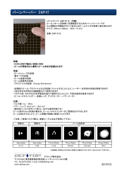
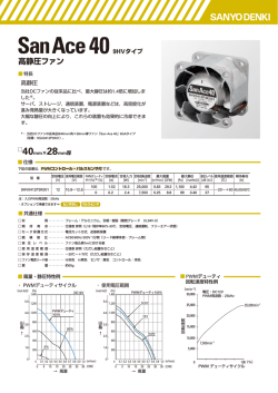
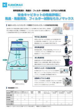
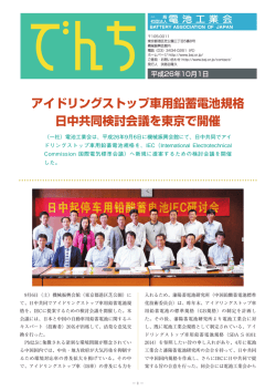
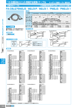
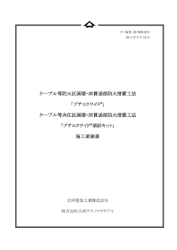
CF/CFM Series
Stackpole Electronics, Inc.
炭素皮膜抵抗器/Carbon Film Resistor
Resistive Product Solutions
特長/Features:
•
•
•
•
•
•
•
•
•
•
•
•
•
•
•
•
商業/工業製品に使用できる、汎用炭素被膜抵抗器
燃焼抑制コーティングを標準で塗布
耐燃性製品は、CFF タイプで供給可能
シーケンサー/自動挿入機に対応
部品サイズに規制がある場合、CFM(mini)で対応可能
リードカット品、リード成形品の供給可能
詳細については、弊社営業に問い合わせください
CF/CFM 部品の標準リード線は、スズメッキ軟銅線を使用
スズメッキ銅線のリードは、CFQ/CFQM の型番で供給可能
General purpose resistor ideal for commercial/industrial applications
Flame retardant coatings standard
Flameproof version available as CFF
Auto sequencing/insertion compatible
CFM (mini) ideal choice when size constraints apply
Cut and formed product is available on select sizes;
Contact Sales Staff
Standard lead wire for CF/CFM is copper plated steel,
with 100% tin over plate
100% tin plate on copper wire is available as type CFQ/CFQM
定格 / Electrical Specifications
最高使用電圧 最高過負荷電圧
定格電力
Maximum
Maximum
形名
Power Rating
Type / Code
Working Voltage
Overload
(Watts) @ 70ºC
(1)
Voltage
絶縁耐電圧
Dielectric
Withstanding
Voltage
抵抗温度係数
Resistance Temperature Coefficient
per Ohmic Range
抵抗値範囲 (Ω)/抵抗値許容差
Ohmic Range (Ω) and Tolerance
2%
5%
CF 18
0.125W
250V
500V
350V
10 - 1M
1 - 22M
CF 14
0.25W
350V
600V
350V
1 - 1M
1 - 22M
CF 12
0.5W
350V
700V
600V
CF 1
1W
500V
1,000V
600V
<10Ω = ±400ppm/ºC
10Ω to 9.99KΩ = 0 ~ -400ppm/ºC
10KΩ to 99KΩ = 0 ~ -500ppm/ºC
100KΩ to 999KΩ = 0 ~ -850ppm/ºC
1MΩ and above = 0 ~ -1500ppm/ºC
10 - 1M
1 - 22M
1 - 1M
1 - 10M
10 - 1M
1 - 10M
10 - 1M
1 - 10M
CF 2
2W
500V
1,000V
600V
CFM 14
0.25W
250V
500V
350V
CFM 12
0.5W
350V
600V
350V
10 - 1M
1 - 10M
CFM 1
1W
600V
1,000V
600V
10 - 1M
1 - 10M
(1) 定格電圧は、 定格電力× 公称抵抗値 による計算値、又は最高使用電圧のいずれか小さい方の値とする。
Lesser of √PR or maximum working voltage.
Catalog Rev Date: 2014/09/17
本カタログに記載の仕様は予告なく変更する場合がございます。
ご注文及びご使用前に納入仕様書等で内容をご確認頂きます様お願い致します。
1
www.seielect.com
[email protected]
CF/CFM Series
Stackpole Electronics, Inc.
炭素皮膜抵抗器/Carbon Film Resistor
Resistive Product Solutions
外形寸法 / Mechanical specifications
形名
Type / Code
CF 18
CF 14
CF 12
CF 1
A : Body Length
3.3 ± 0.3
6.0 ± 0.3
8.5 ± 1.0
11.0 ± 1.0
CF 2
CFM 14
CFM 12
CFM 1
15.0 ± 1.0
3.3 ± 0.3
6.0 ± 0.3
9.0 ± 0.5
寸法 / Dimensions (mm)
B : Body Diameter
C : Lead Length(Bulk)
1.7 ± 0.3
28.0 ± 3.0
2.3 ± 0.3
28.0 ± 3.0
2.7 ± 0.5
28.0 ± 3.0
4.5 ± 0.5
30.0 ± 3.0
5.0 ± 0.5
1.7 ± 0.3
2.3 ± 0.3
3.5 ± 0.5
D : Lead Diameter
0.45 ± 0.08
0.55 ± 0.08
0.70 ± 0.05
0.70 ± 0.05
34.0 ± 4.0
28.0 ± 3.0
28.0 ± 3.0
28.0 ± 3.0
0.70 ± 0.05
0.45 ± 0.08
0.55 ± 0.08
0.70 ± 0.05
性能 / Performance Characteristics
試験項目
Test
試験方法 / 安全規格
Standard / Method
規格値
Test Results
短時間過負荷
Short Time Overload
JIS C 5201-1 4.13
± 0.5%
はんだ耐熱性
Resistance to Solder Heat
JIS C 5201-1 4.18
± 0.5%
絶縁耐電圧
Dielectric Withstanding Voltage
JIS C 5201-1 4.7
± 0.5%
定格負荷
Load Life
JIS C 5201-1 4.25.1
± 1%
端子強度
Terminal Strength
JIS C 5201-1 4.16
± 0.2%
耐湿負荷
Moisture Resistance
JIS C 5201-1 4.23
± 0.5%
使用温度範囲 / Operating Temperature Range: -55°C to +155°C
Power Derating Curve
100
-55ºC
70ºC
Power Load (%)
80
60
40
20
155ºC
0
-60
-40
-20
0
Catalog Rev Date: 2014/09/17
本カタログに記載の仕様は予告なく変更する場合がございます。
ご注文及びご使用前に納入仕様書等で内容をご確認頂きます様お願い致します。
20
40
60
80
100
Ambient Temperature (ºC)
2
120
140
160
180
www.seielect.com
[email protected]
CF/CFM Series
Stackpole Electronics, Inc.
炭素皮膜抵抗器/Carbon Film Resistor
Resistive Product Solutions
Single Pulse Power
Catalog Rev Date: 2014/09/17
本カタログに記載の仕様は予告なく変更する場合がございます。
ご注文及びご使用前に納入仕様書等で内容をご確認頂きます様お願い致します。
3
www.seielect.com
[email protected]
CF/CFM Series
Stackpole Electronics, Inc.
炭素皮膜抵抗器/Carbon Film Resistor
Resistive Product Solutions
繰り返しパルスに関する情報/Repetitive Pulse Information
If repetitive pulses are applied to resistors, pulse wave form must be less than “Pulse limiting voltage”,
“Pulse limiting current” or “Pulse limiting wattage” calculated by the formula below.
Vp
=
K√P x R x T/t
lp
=
K√P/R x T/t
Pp
=
K2 x P x T/t
Where:
Vp:
lp:
Pp:
P:
T:
Pulse limiting voltage (V)
Pulse limiting current (A)
Pulse limiting wattage (W)
Power rating (W)
Repetitive period (sec)
R:
t:
K:
[Vr:
Nominal resistance (ohm)
Pulse duration (sec)
Coefficient by resistors type (refer to below matrix)
Rated Voltage (V), Ir: Rated Current (A)]
If T>10 → T = 10 (sec), T/t>1000 → T/t = 1000
If T>10 and T/t>1000, “Pulse Limiting power (Single pulse) is applied
If Vp<Vr (lp<lr or Pp<P), Vr (lr, P) is Vp (lp, Pp)
Pulse limiting voltage (Current, Wattage) is applied at less than rated ambient temperature.
If ambient temperature is more than the rated temperature (70º), please decrease power rating
according to “Power Derating Curve”
Note 5: Please assure sufficient margin for use period and conditions for “Pulse limiting voltage”
Note 6: If the pulse waveform is not square wave, please judge after transform the waveform into square
wave according to “Waveform Transformation to Square Wave” information.
Note 1:
Note 2:
Note 3:
Note 4:
Coefficient (K) Matrix
Resistor Type
RNF, RNMF
K
0.7
CF, CFM, HDM
0.8
ASR, SPR, ASRM, SPRM
RSPF, RSPL
1
0.9
RSF, RSMF
FRN
0.8
0.6
Catalog Rev Date: 2014/09/17
本カタログに記載の仕様は予告なく変更する場合がございます。
ご注文及びご使用前に納入仕様書等で内容をご確認頂きます様お願い致します。
4
www.seielect.com
[email protected]
CF/CFM Series
Stackpole Electronics, Inc.
炭素皮膜抵抗器/Carbon Film Resistor
Resistive Product Solutions
波形の矩形波への換算/Waveform Transformation to Square Wave
1. Discharge curve wave with time constant “t” Square wave
2. Damping oscillation wave with time constant of envelope “t” Square wave
3. Half-wave rectification wave Square wave
4. Triangular wave Square wave
5. Special wave Square wave
Catalog Rev Date: 2014/09/17
本カタログに記載の仕様は予告なく変更する場合がございます。
ご注文及びご使用前に納入仕様書等で内容をご確認頂きます様お願い致します。
5
www.seielect.com
[email protected]
CF/CFM Series
Stackpole Electronics, Inc.
炭素皮膜抵抗器/Carbon Film Resistor
Resistive Product Solutions
Current Noise
アキシャルリードテーピング仕様
Lead Tape Specifications: Reeled in accordance eith EIA-296-F (mm)
品種
数量
Type / Code
CF 18, CFM 14
CF 14, CFM 12
CF 12
CF 1
CF 2
Qty per Reel
5,000
5,000
5,000
2,000
1,000
寸法 / Dimensions (mm)
A max.(1)
63.7
67.0
69.5
75.5
79.5
B max
343.0
343.0
343.0
343.0
343.0
C
5.0 ± 0.5
5.0 ± 0.5
5.0 ± 0.5
5.0 ± 0.5
10.0 ± 0.5
クラス
D(2)
52.4 +2.0 / -1.0
52.4 +2.0 / -1.0
52.4 +2.0 / -1.0
52.4 +2.0 / -1.0
52.4 +2.0 / -1.0
Tape
6.35
6.35
6.35
6.35
6.35
Class
I
I
I
I
I
Dimension "E":
(1)
(2)
This is a non-critical dimension that does not have a tolerance in the standard.
Range of diameters is from 13.9 mm to 38.1 mm..
Reference value only. The "A" dimension shall be governed by the overall length of the taped component.
The distance between flanges shall be 1.5 mm to 8.0 mm greater than the overall component.
The given dimension "D" expresses the standard width spacing. A 26mm narrow spacing is available as
option "N" packaging code.
Catalog Rev Date: 2014/09/17
本カタログに記載の仕様は予告なく変更する場合がございます。
ご注文及びご使用前に納入仕様書等で内容をご確認頂きます様お願い致します。
6
www.seielect.com
[email protected]
CF/CFM Series
Stackpole Electronics, Inc.
炭素皮膜抵抗器/Carbon Film Resistor
Resistive Product Solutions
形名構成 / How to Order
CF
CFF
CFM
CFQ
CFQM
1
2
3
4
5
6
7
8
9
10
C
F
1
2
J
T
1
0
0
K
品種
Product Series
Standard
Flameproof
Mini
Tin plating on copper wire
Tin plating (mini)
サイズ
Size
18
14
12
1
2
定格電力
Power Rating
0.125W
0.25W
0.5W
1W
2W
抵抗値許容差
Tolerance
Code Tol
G
2%
J
5%
Code
Description
B
Bulk
T
Tape and Reel
A
Catalog Rev Date: 2014/09/17
本カタログに記載の仕様は予告なく変更する場合がございます。
ご注文及びご使用前に納入仕様書等で内容をご確認頂きます様お願い致します。
7
Ammo
包装形状
Packaging
Size
CF18, CFM14, CF14, CFM12
CF12, CFM1, CF1, CF2
CF18, CFM14, CF14,
CFM12, CF12
CFM 1
CF1
CF2
CF18, CFM14, CF14,
CFM12
CF12, CFM1
CF1, CF2
抵抗値
Resistance Value
Quantity
1,000
5,000
2,500
2,000
1,000
10進数の4桁表示
Four characters with
the multiplier used as
the decimal holder.
10 ohm = 10R0
10.2 kohm = 10K2
1 Mohm = 1M00
5,000
2,000
1,000
www.seielect.com
[email protected]
© Copyright 2026 Paperzz