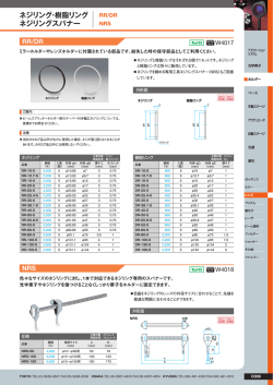
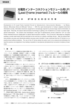
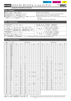
導電性高分子アルミ固体電解コンデンサ
PZ-CAP
CONDUCTIVE POLYMER ALUMINUM SOLID ELECTROLYTIC CAPACITORS
◆リード線形 導電性高分子アルミ固体電解コンデンサ呼称方法/LEAD WIRE TYPE PART NUMBER
定格電圧
Rated Voltage
シリーズ名
Series
静電容量
Capacitance
静電容量許容差
Capacitance Tolerance
Rated Voltage(V)
Code
Cap.(μF)
Code
25
25
220
220
63
63
10
10
副記号
Option
リード加工記号
Lead Forming
To
l
e
r
ance Code
±20%
6.3×8
8×10
10×13
TA, KC,
CA etc
M
D×L
ケースサイズ
Case Size
御注文の際には、
定格電圧、
シリーズ名、静電容量、
リード加工、
ケースサイズまで御連絡ください。
Please indicate the above information, when you inquire.
例)
: Example
・ロング品 Long lead type
・テーピング品 Taping type
35
50
PZA
PZC
82
47
M
M
T8
8×12.5
10×13
◆副記号/OPTION
各シリーズのページをご確認ください。
Please confirm each series page.
◆チップ形 導電性高分子アルミ固体電解コンデンサ呼称方法/CHIP TYPE PART NUMBER
定格電圧
Rated Voltage
シリーズ名
Series
静電容量
Capacitance
静電容量許容差
Capacitance Tolerance
Rated Voltage(V)
Code
Cap.(μF)
Code
25
25
220
220
63
63
22
22
副記号
Option
To
l
e
r
ance Code
±20%
D×L
ケースサイズ
Case Size
8×12
10×15
M
御注文の際には、
定格電圧、
シリーズ名、
静電容量、
ケースサイズまで御連絡ください。
Please indicate the above information, when you inquire.
例)
: Example
35
PAV
150
M
10×15
梱包単位/PACKAGING SPECIFICATION
◆リード線端子形/LEAD WIRE TYPE
サイズ
SIZE
(㎜)
φ6.3×8
φ8×8
φ8×10
φ8×12.5
φ10×10
φ10×13
ロングリード品
リード加工品
LONG LEAD
LEAD FORMING
バラ梱包
バラ梱包
( )
( )
BULK PACKAGE
BULK PACKAGE
1,000
1,000
1,000
1,000
1,000
1,000
1,000
1,000
1,000
1,000
1,000
1,000
Q’
ty
(pcs)
テーピング品
TAPING
2,000
1,000
1,000
1,000
500
500
梱包単位につきましては上記と異なる場合がございます。
There are some differences between actual package quantity and above list.
◆縦形チップ形/V Chip Type
サイズ
SIZE
(㎜)
φ8×10.5
φ8×12
φ8×15
φ10×10.5
φ10×12
φ10×15
W3
φC
(㎜) (㎜)
26
26
26
26
26
26
382
382
382
382
382
382
Q’
ty
(pcs)
1リール数量
Q’
ty
(pcs/reel)
500
400
350
500
400
250
W3、
φCについてはリールの項をご参照ください。
Please refer to TAPING REEL for「W3」
「φC」.
標準外装梱包単位
Standard Shipping
Carton Quantity
(pcs/Box)
2,000
1,600
1,400
2,000
1,600
1,000
導電性高分子アルミ固体電解コンデンサ
PZ-CAP
CONDUCTIVE POLYMER ALUMINUM SOLID ELECTROLYTIC CAPACITORS
◆テーピング仕様/TAPING SPECIFICATIONS
◆ラジアルリード形(04形)
テーピング形状寸法図/DIMENSIONS
△p △p
P
P2
Fig.1
P2
Fig.2
△h △h
△p △p
P
φD
L
L
φD
P1
φd
W1
W2
H
L1
W
W0
W1
W2
W
W0
L1
φD0
P0
φD0
t
P0
φd
F
H0
F
H
P1
◆規格表/SPECIFICATION TABLE
(mm)
項 目
記号
Items
Code
リード加工記号
Taping code
形状寸法図
Applicable Fig. No.
※
φ8
φ6.3
8mm Height
φ10
許容差
Tolerance
10mm or more Height
T5
TZ
TA
T7
TA
T7
T8
Fig.2
Fig.1
Fig.1
Fig.2
Fig.1
Fig.2
Fig.2
リード線径
φd
0.45
0.6
±0.05
本体高さ
L
9.5
15.0
MAX
ボディーピッチ
P
12.7
±1.0
送り穴ピッチ
P0
12.7
±0.2
送り穴位置ズレ
P1
送り穴位置ズレ
P2
リードピッチ
F
台紙幅
W
18.0
±0.3
粘着テープ幅
W0
5.0
MIN
送り穴位置ズレ
W1
9.0
±0.5
粘着テープズレ
W2
1.5
MAX
ボディ下面位置
H
リードクリンチ高さ
H0
リード線はみ出し
L1
0.5
MAX
φD0
4.0
±0.2
ボディーの倒れ
△h
1.0
MAX
ボディーの倒れ
△p
1.0
MAX
テープの総厚み
t
0.6
±0.3
Dia. of lead
Height of body
Distance from center to center of next body
Distance from center to center of next driving hole
Distance between center of driving hole and lead
Distance between center of driving hole and body
Pitch of lead
Width of mounting tape
Width of adhesive tape
Distance between center of driving hole and mounting tape edge
Max. allowable distance between mounting and adhesive tape edges
Distance between center of driving hole and bottom of body
Distance between center of driving hole and clinch part of lead
End of lead
送り穴径
Dia. of driving hole
Off alignment of body top
Off alignment of body top
Sum of thickness for mounting and adhesive tape without lead dia
梱包数量
(個)
Quantity (pcs)
5.1
3.85
4.6
3.85
4.6
3.85
6.35
2.5
5.0
17.5
5.0
20.0
2000
※個別に許容差が設定されている場合は、
その数値が優先されます。
±1.0
3.5
※For the case that tolerance is specified individually, the value shall have the priority.
3.5
5.0±0.8
1000
+0.8
−0.2
18.5 +0.75
−0.5 ±0.75
16.0
16.0
±0.5
±0.5
500
導電性高分子アルミ固体電解コンデンサ
PZ-CAP
CONDUCTIVE POLYMER ALUMINUM SOLID ELECTROLYTIC CAPACITORS
◆リード線加工仕様/LEAD CUTTING FORMING SPECIFICATIONS
プリント基板取り付けが容易となる様、
リードフォーミング、
リードカットを行った製品及びプリント基板自立形用に特殊加工
(キンクフォーミング)
を行った製品を製造しております。
Rubycon provides lead-formed and lead-cut products to facilitate mounting on printed circuit boards, as well as products
with leads specially processed (kink formed) for self supporting insertions to printed circuit boards.
(mm)
φD
L+αMAX
・リードフォーミング
Lead forming
φD
F±0.5
φd±0.05
(φ6.3∼φ8)
Lead forming code : FA
2.5MAX
5±0.5
6.3
8
L
L=8
L≧10
α
1.5
2.0
φd
0.45
0.6
5.0
F
(mm)
φD 6.3
F
φD
F±0.5
L+αMAX
・リードカット
Lead cutting
(φ6.3∼φ10)
Lead cutting code : CA
CC
CE
φd±0.05
2.5
8
10
3.5
5.0
L
L=8
L≧10
α
1.5
2.0
φd
0.45
0.6
5.0:CA
H±0.5
H
4.0:CC
3.5:CE
L+αMAX
E±0.2
φD
・キンクリードフォーミング
Kinked lead forming
(mm)
P MAX
φD
(φ8)
Kinked lead forming code : KC
1.0
H2+
−0.5
F±0.5
φd±0.05
H3MAX
H1±0.5
L+αMAX
E±0.2
φD
・キンクリードカット
Kinked lead cutting
8
L
P MAX
L≧10
α
2.0
φd
0.6
H1
4.5
H2
2.8
H3
2.5
5.0
P
1.0
1.2
φd±0.05
Code
1.3
KC
F±0.5
(φ10)
Kinked lead cutting code : KC
−
F
E
1.0
H2 +
−0.5
10
H1±0.5
・横置き対応品
(φ10)
/Low profile with horizontal mounting
2.3±0.5
タイプA
Type A
(mm)
タイプB
Type B
φD
φD
Code
φd±0.05
H±0.5
H±0.5
F±0.5
RI
RK RX SG
φd
0.6
F
5.0
H
Type
F±0.5
10
4.0
A
3.5
B
A
B
導電性高分子アルミ固体電解コンデンサ
PZ-CAP
CONDUCTIVE POLYMER ALUMINUM SOLID ELECTROLYTIC CAPACITORS
適応 object:表面実装形コンデンサ Chip type capacitors
2±0.1
+0.1
0
±0.1
t1
W2
±0.1
t2
A2
P
サイズ
Size
±0.3
F±0.1
φ1.5
B2
A
4±0.1
1.75±0.1
◆テーピング仕様/TAPING DIMENSIONS
A'
A-A' 断面
Cross section of A-A'
W2
(mm)
A2
(mm)
B2
(mm)
P
(mm)
t2
(mm)
F
t1
(mm)
(mm)
φ8×10.5
24.0
8.7
8.7
16.0 11.0 11.5
0.4
φ8×12
24.0
8.7
8.7
16.0 12.5 11.5
0.5
φ8×15
24.0
8.7
8.7
16.0 15.0 11.5
0.5
φ10×10.5
24.0 10.7 10.7 16.0 11.0 11.5
0.4
φ10×12
24.0 10.7 10.7 16.0 12.5 11.5
0.5
φ10×15
24.0 10.7 10.7 20.0 15.0 11.5
0.5
◆リール/TAPING REEL
φ50MIN
φC MAX
引出方図
Leading direction
極性
Polarity
φ13±0.5
φ23±0.5
※W3、
φCについては梱包単位をご参照ください。
W3±0.5
御要望により、
リユースリールにも対応可能です。
配給,
回収について別途御相談させていただきます。
Reuseable reels are available according to your
request.
Please consult in regard to establishing supply
and withdrawal system.
Please refer to PACKAGING SPECIFICATION for「W3」
「φC」.
◆鉛フリータイプリフロー許容条件/LEAD FREE TYPE REFLOW SOLDERING CONDITION
●ケースサイズφ8∼φ10㎜品 Size φ8∼φ10
製品温度
Temperature at surface of capacitor(℃)
Series Size T(℃) T1(℃) t(sec) t1(sec) Reflow
1) コンデンサ表面温度がT℃以下である事。
①
②
③ cycle
Temperature at surface of capacitor shall not exceed T℃.
250 230 60 40
2
φ8
2) コンデンサ表面温度は200℃以上の時間がt秒, T1℃以上の
PAV
時間がt1秒を越えない事。
PCV φ10
260 230 60 40
1
Period that temperature at surface of capacitor becomes more than
245 230 60 40
2
φ8
200℃ and T1℃ shall not exceed t and t1 seconds, respectively.
PFV
φ10
260 230 60 40
1
3)予熱は100℃∼180℃で120秒以内である事。
Preheat shall be made at 100℃∼180℃ and for maximum 120 seconds.
4) 2回目のリフローを行う場合、必ずコンデンサの温度が室温まで十分に冷えていることをご確認ください。
Please ensure that the capacitor became cold enough to the room temperature before the second reflow.
ピーク温度・5秒
Peak temperature・5 sec.
T℃ Max.
T
T1
①ピーク温度 Peak temperature
200
②200℃を超える時間〈MAX〉
Time more than 200℃
t1 sec Max.
③T1を超える時間〈MAX〉
Time more than T1
※許容条件を越える場合は御相談ください。
Please contact us if the condition is over the maximum.
予熱
Preheat
100℃∼180℃,120 sec Max.
t sec Max.
時間
Time (sec)
◆推薦ランドパターン/RECOMMENDED LAND SIZE
a
(mm)
b
c
d
b
サイズ
Size
a
b
φ8
2.2
4.1
3.0 11.2
φ10
2.2
4.3
4.5 13.1
c
d
© Copyright 2026 Paperzz