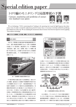
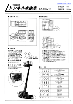
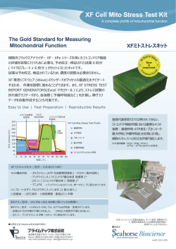
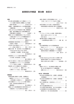
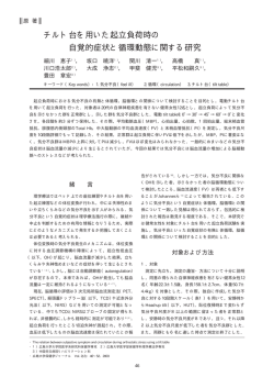
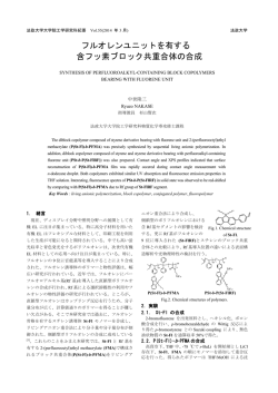
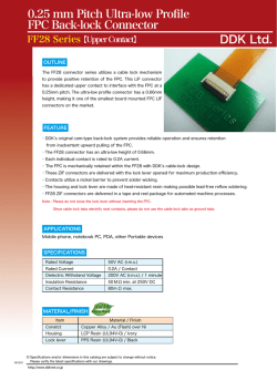
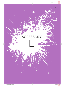
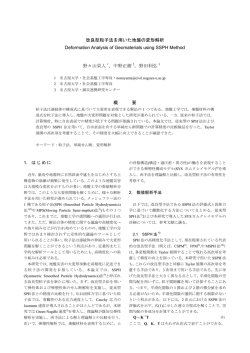
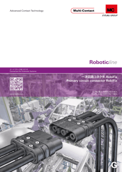
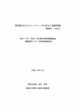
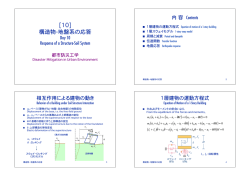
日本機械学会 2011 年度年次大会 [2011.9.11-14]
CopyrightⒸ2011 一般社団法人 日本機械学会
S111032
遠心力の影響を考慮した傾斜ウェブを持つ三次元構造薄肉平歯車
の歯面接触応力と歯元曲げ応力の理論解析*
李 樹庭*1
Surface Contact Stress and Root Stress Analyses of Three-Dimensional, Thin-rimmed Spur Gears
with Inclined Web under Torque and Centrifugal Load Conditions
Shuting LI*1
*1
Shimane Univ. Dept. of Electronic Control System Engineering
1060 Nishikawatsu-Cho, Matsue-shi, Shimane-ken 690-8504, Japan
Deformations of thin-rimmed spur gears with inclined webs are analyzed by finite element method (FEM) when
the gears are loaded under centrifugal forces. Then loaded tooth contact analyses of the gears with centrifugal
deformations are conducted by mathematical programming method and FEM when the gears contact with a solid
mating gear. Tooth contact stress and root bending stress are analyzed by FEM at the same time. It is found that
centrifugal load exerts greater effect on tooth root stress when gear speed is over 10000rpm. So, it is necessary to take
the effect of centrifugal load into account in tooth root strength calculation when gear speed is over 10000rpm. It is also
found that centrifugal deformations of the gears almost have no effect on tooth contact patterns of the gears having
inclined webs, though it has been reported that centrifugal deformations of the gears with the straight web have great
effect on tooth contact patterns. This is because shape of the inclined web after centrifugal deformation is completely
different from the shape of the straight web after centrifugal deformation. This difference results in the difference of
tooth attitudes and then the difference of the effects of tooth centrifugal deformations on tooth contact patterns. It can be
concluded that the effect of centrifugal deformations of the inclined web gears on tooth contact pattern can be neglected
even if the gears have very high speeds.
Key Words : Thin-rimmed Gear, Spur gear, Centrifugal Load, Contact Analysis, Stress Analysis
1. 緒
言
傾斜ウェブを持つ三次元構造薄肉歯車(以下,傾斜ウェブ歯車とする)はコンパクト化,省スペース設計のた
めに動力伝達要素として航空機に使われることがある(1).しかし,この歯車は複雑な構造で,かつ航空機に使用
される場合には,回転数が高く,強度に及ぼす遠心力の影響を検討すべきであると思われるので,現在,この歯
車の強度計算問題はまだ完全に解決されていないのが現状である.
歯車強度に及ぼす遠心力の影響について,Liu ら(2),Lewicki(3)と Li(4)などの研究があるが,これらの研究
は傾斜ウェブの影響を論じなかったので,傾斜ウェブ歯車の強度に及ぼす遠心力の影響は不明のままである.
本研究では,まず三次元有限要素法(FEM)を用いて高速回転する傾斜ウェブ歯車の遠心変形を解析し,そし
て遠心変形された傾斜ウェブ歯車は厚肉歯車とかみあう時の歯の接触解析を行い,歯面荷重分布を求める.また
その歯面荷重を用いて傾斜ウェブ歯車の歯面接触応力と歯元曲げ応力を解析する.最後に遠心変形と遠心応力の
解析結果の妥当性を検討した上で,歯面接触応力と歯元曲げ応力に及ぼすウェブ位置、ウェブ傾斜角度及び歯車
回転数の影響を調べる.
*1
正員,島根大学(〒690-8504 島根県松江市西川津町 1060)
E-mail:[email protected]
[No.11-1] 日本機械学会 2011 年度年次大会 DVD-ROM 論文集 〔2011.9.11-14,東京〕
2.モデル,解析方法及び妥当性検討
2.1 研究対象とする歯車の構造及び諸元
解析対象とする傾斜ウェブ歯車の構造を図1に示す.図1の(a),(b)と(c)はそれぞれウェブが歯の中央部の左側,
歯の中央部と歯の中央部の右側に配置された時の三種類の傾斜ウェブ歯車である.また相手の厚肉歯車を図 1(d)
に示している.これらの歯車は歯数 Z1=Z2=50,モジュール m=4,圧力角度=20°,転位係数 X1=X2=0,歯幅=40mm,
リム厚さ=5mm,ウェブ厚さ=4mm,ウェブ傾斜角度=45°である.解析の際,トルク=30kgm である.
40
30
10
20
40
7
4
(b) Center web
(c) Right web
50
85
208
50
85
208
180
(a) Left web
20
45 ‹°
Z
164
‹
45 °
45 ‹°
26
(d) Mating gear
Fig.1 Spur gears with inclined webs and the mating gear
2.2 遠心力と遠心変形の理論解析
傾斜ウェブ歯車の遠心力と遠心変形の解析は FEM を用いる(4).解析の際,まず各要素の遠心力を体積力とし
て算出し,そしてこの体積力を要素の節点力に換算する.換算された要素節点の遠心力を用いて,FEM で傾斜ウ
ェブ歯車の遠心変形を求めて,そして遠心応力を求める.図2は遠心力による傾斜ウェブ歯車(図 1(c)の歯車)
と真っすぐウェブ歯車の変形様子を表すものである.図2より,傾斜ウェブ歯車の遠心変形は真っすぐウェブ歯
車の遠心変形(4)と大きく異なることが分かる.
傾斜ウェブ
真っすぐウェブ
Fig.2 Image of the gears deformed under centrifugal load
Fig.3 FEM model used for loaded tooth contact analysis
2.3 負荷トルク条件で遠心変形された傾斜ウェブ歯車の接触解析
遠心変形された傾斜ウェブ歯車の歯の接触解析は従来開発してきたもの(5)を用いる.その際,図3に示す FEM
モデルを用いる.相手の歯車は厚肉であるので,部分構造モデルを用いる.接触解析により,遠心変形された傾
斜ウェブ歯車の歯面荷重分布を求め,そしてその荷重を用いて歯面接触応力と歯元曲げ応力を計算する.解析の
境界条件は従来(5)と同じようにした.
2.4 解析結果の妥当性検討
遠心変形と遠心応力解析結果の妥当性は既に既報(4)で検討された.また接触解析結果の妥当性も文献(5)で
検討されたので,詳細については,文献(4-5)を参照のこと.
3.解析結果及び分析
3.1 遠心力による傾斜ウェブ歯車の歯元応力
図1(a),(b)と(c)の歯車に対して,遠心力による傾斜ウェブ歯車の歯元引張り側の曲げ応力を算出し,最大値位
置における歯すじ方向の分布を図 4(a),(b)と(c)に示す.
図4より,
歯車用材料の曲げ疲労限度応力
(例えば SCM415
の場合には,382MPa)に対して,回転数は 10000rpm を超えると,遠心力による歯元応力は約 30~35MPa に上る
ので,歯元曲げ強度に対する遠心力の影響を無視できないことが分かる.また,ウェブ位置は歯の左側にある場
合には,歯元応力は最大となり,右側の場合には,歯元応力は最小となり,その差は約 18%であることが分かる.
Root tensile stress MPa
500
400
5000rpm
10000rpm
20000rpm
40000rpm
300
200
100
600
600
Web position
520MPa
Root tensile stress MPa
562MPa
Web position
Root tensile stress MPa
600
500
400
5000rpm
10000rpm
20000rpm
40000rpm
300
200
100
0
400
5
10
15
20
25
30
35
200
100
0
40
Tooth longitudinal dimension mm
5000rpm
10000rpm
20000rpm
40000rpm
300
0
0
Web position
461MPa
500
0
5
10
15
20
25
30
35
(a) Left web
0
40
Tooth longitudinal dimension mm
5
10
15
20
25
30
35
40
Tooth longitudinal dimension mm
(b) Center web
(c) Right web
Fig.4 Tooth root tensile stresses resulted only from centrifugal load
Left web (45deg) Speed=0rpm
60
3E2 2.4E2
-0.05
5.4E2
4.2E2 3.6E2
4.8E2
0.00
0.05
1.8E2
0.10
0.15
60
1.2E2
5.6E2
4.9E2
4.2E2
0.05
2.8E2
0.10
Geometric contact line
2.1E2
5
3.5E2
6.3E2
5.6E2
0.00
0.05
0.10
Geometric contact line
2.1E2
(a) Straight & 0rpm
5
10
15
20
25
30
Tooth longitudinal dimension mm
35
(b) Inclined & 0rpm
10
15
20
25
30
35
Tooth longitudinal dimension mm
2.8E 2 70
4.9E2
0.05
4.2E 2
Geometric contact line
0.10
2.1E2
0.15
Maximum stress=668MPa
5
5.6E2
6.3E2
0.00
2.8E2
0
40
3.5E2
-0.05
4.2E2
0.15
0
40
1.4E2
4.9E2
Maximum stress=668MPa
10
15
20
25
30
35
Tooth longitudinal dimension mm
-0.10
70
-0.05
0.15
Maximum stress=594MPa
0
1.4E2
3.5E2
6.3E2
0.00
Left web (45deg) Speed=20000rpm
Torque=30kgm
-0.15
Torque=30kgm
-0.10
70
-0.05
Geometric contact line
Left web (45deg) Speed=5000rpm
-0.15
Torque=30kgm
-0.10
Contact width mm
1.2E2
Contact width mm
Contact width mm
-0.15
Torque=30kgm
-0.10
Contact width mm
Left web (0deg) Speed=0rpm
-0.15
40
1.4E2
0
Maximum stress=671MPa
5
(c) Inclined & 5000rpm
10
15
20
25
30
Tooth longitudinal dimension mm
35
40
(d) Inclined & 20000rpm
Fig.5 Contour lines of tooth contact stresses [straight left web and inclined left web gears]
1.5E2 1E2
3E2
4E2
-0.05
50
2E2
3.5E2
4.5E2
0.00
4E2
0.05
3.5E2
3E2
2E2 2.5E2
1.5E2
50
0.10
1E2
1.2E2
3.6E2 3E2
-0.05
5.4E2
0.00
4.8E2
5
10
15
20
25
30
35
2.4E2
0.05
0.10
60
1.8E2
Geomatric contact line
1.2E2
0.15
-0.10
3.6E2 3E2
-0.05
5.4E2
0.00
40
0
5
Tooth longitudinal dimension mm
10
15
20
25
30
0.10
40
60
1.8E2
1.2E2
0
Tooth longitudinal dimension mm
(a) Straight & 0rpm
4.2E2
2.4E2
0.15
35
4.8E2
0.05
(b) Inclined & 0rpm
5
10
15
20
25
30
35
Tooth longitudinal dimension mm
Center web (45deg) Speed=20000rpm
Torque=30kgm
-0.15
Geometric contact line
Maximum contact stress=587MPa
Maximum stress=586MPa
Maximum stress =500 MPa
0
4.2E2
Center web (45deg) Speed=5000rpm
Torque=30kgm
60
-0.15
60
-0.10
Geometric contact line
0.15
Center web (45deg) Speed=0rpm
Torque=30kgm
-0.15
Contact width mm
2.5E2
Contact width mm
Contact width mm
-0.10
Contact width mm
Center web (0deg) Speed=0rpm
Torque=30kgm
-0.15
-0.10
60
-0.05
3.6E2 3E2
4.2E2
5.4E2
4.8E2
2.4E2
0.00
0.05
1.8E2
0.10
1.2E2
Geometric contact line
Maximum contact stress=594MPa
0.15
0
40
5
10
15
20
25
30
35
40
Tooth longitudinal dimension mm
(c) Inclined & 5000rpm
(d) Inclined & 20000rpm
Fig.6 Contour lines of tooth contact stresses [straight center web and inclined center web gears]
2.2E2
1.8E2
3.6E2
0.05
5.4E2
4.2E2
3E2
60
1.2E2
0.10 Geometric c ontact line
0.15 M aximum stress=594MPa
0
5
0.00
35
(a) Straight & 0rpm
40
3.3E2
4.4E2
0.10
1.7E2
1.1E2
2.2E2
2.8E2
55
Geometric contact line
5
10
15
20
25
30
Tooth longitudinal dimension mm
35
(b) Inclined & 0rpm
4.4E2
0.05
3.3E2
0.10
1.1E2
1.7E 2
40
2.8E2
2.2E2
55
Geometric contact line
Maximum stress=507MPa
0
5
10
15
20
25
30
35
Tooth longitudinal dimension mm
1.7E2
55
1.1E2
3.3E2
-0.05
5E2
0.00
Right web (45deg) Speed=20000rpm
Torque=30kgm
-0.15
-0.10
3.3E2
3.9E2
0.15
Maximum stress=506MPa
0
55
2.2E 2
1.7E2 1.1E2
2.8E2
-0.05
0.05
3.3E2
Right web (45deg) Speed=5000rpm
Torque=30kgm
-0.15
-0.10
1.7E2 1.1E2
5E2
0.15
10
15
20
25
30
Tooth longitudinal dimension mm
2.8E2
3.9E2
-0.05
4.8E2
55
Contact width mm
-0.10
-0.05
0.00
Torque=30kgm
2.4E2
Contact width mm
Contact width mm
Right web (45deg) Speed=0rpm
60
-0.15
1.2E 2
-0.10
Contact width mm
Right web (0deg) Speed=0rpm
-0.15 Torque=30kgm
40
(c) Inclined & 5000rpm
3.9E2
5E2
2.2E2
2.8E2
4.4E2
0.00
0.05
2.8E2
0.10
1.1E2
2.2E2
1.7E2
55
Geometric contact line
0.15
Maxim um stress=515MPa
0
5
10
15
20
25
30
35
Tooth longitudinal dimension mm
40
(d) Inclined & 20000rpm
Fig.7 Contour lines of tooth contact stresses [straight right web and inclined right web gears]
3.2 遠心変形された傾斜ウェブ歯車の歯面接触応力
遠心変形された図1(a),(b)と(c)に示す三種類の歯車は、厚肉歯車と最悪かみあい位置においてかみあう時の歯
面接触応力を解析し,その結果を図5,6と7の b,c と d にそれぞれ示す.また比較のため,これらの三種類歯
車のウェブは真っすぐになった場合の歯面接触応力も算出し,その結果を図5,6と7の a にそれぞれ示す.
図5と6より,真っすぐウェブの場合に比べると,45 度傾斜ウェブの Left web 歯車と Center web 歯車の歯面最
大接触応力はそれぞれ約 12.5%と 17.2%大きくなり,
また歯車の遠心変形は歯の最大接触長さに影響を及ぼすが,
最大歯面接触応力に殆ど影響を及ぼさないことが分かる.
図7より,Right web 歯車の場合には,真っすぐウェブの場合に比べると,45 度傾斜ウェブ歯車の最大歯面接
触応力は約 15%下がり,また歯車の遠心変形は最大接触応力に殆ど影響を及ぼさないことが分かる.
3.3 遠心変形された傾斜ウェブ歯車の歯元曲げ応力
遠心変形された図1(a),(b),(c)に示す三種類歯車に対して,トルクを受ける時に歯元 30 度接線点の引張り
側の歯元曲げ応力を算出し,その結果をそれぞれ図8(a),(b)と(c)に示す.また比較のために,真っすぐウェブ構
造歯車の歯元応力も算出し,図中に同時に示している.図8より,歯元応力に及ぼすウェブの傾きの影響が大き
いが,歯元応力に及ぼす歯車の遠心変形の影響は殆どないことが分かる.
40
Straight web
20
Torque=30kgm
10
0
Inclined web
0rpm
10000rpm
40000rpm
-10
-20
-30
5000rpm
20000rpm
40
Center web; tooth root(30deg point)
30
Torque=30kgm
Straight web
20
Root tensile stress M Pa
Left web; tooth root(30deg point)
30
Root tensile stress MPa
Ro ot tensile stress
M Pa
40
10
0
-10
-30
5000rpm
20000rpm
0
5
10
15
20
25
30
Tooth longitudinal dimension mm
35
40
0
(a)Left web
5
10
15
20
10
0
25
30
35
Inclined web
0rpm
10000rpm
40000rpm
-20
-30
-40
-40
Straight web
Torque=30kgm
20
-10
Inclined web
0rpm
10000rpm
40000rpm
-20
Right web; tooth root(30deg point)
30
40
Tooth longitudinal dimension mm
-40
0
5
10
15
20
25
5000rpm
20000rpm
30
35
40
Tooth longitudinal dimension mm
(b)Center web
(c)Right web
Fig.8 Root tensile stress distributions along tooth longitudinal direction
4.結
語
1)回転数は 10000rpm を超えると,遠心力による歯元曲げ応力が大きくなるので,歯車の歯元曲げ強度計算
に遠心力の影響を考慮すべきである.
2)三次元構造薄肉歯車のウェブは真っすぐである場合には,歯の遠心変形は歯の当たりパターンに影響を及
ぼすが,ウェブを 45 度傾斜させると,歯の遠心変形は歯の当たりパターンに殆ど影響を及ぼさないこと
が分かる.
3)薄肉歯車の歯面接触応力及び歯元曲げ応力に及ぼすウェブ傾斜及び傾斜ウェブの配置位置の影響が大きい
ことが分かる.
文
献
(1) 和才哲也,金森渉,
“航空機用歯車”
,機械設計,Vol.26, No.3 (1982), pp.62-66.
(2) G. Liu, D.W. He, Y.W. Shen and X. Q. Gao, “Dynamic stress and centrifugal stress analyses of high speed coupled gears”,
Journal of Gears (in Chinese), Vol.15, No.2 (1991), pp.1-4.
(3) D. G. Lewicki, “Effect of speed (centrifugal load) on gear crack propagation direction”, The JSME International Conference on
Motion and Power Transmission (MPT2001-Fukuoka), Vol. 2 (2001), pp.518-523.
(4) S. Li, “Centrifugal load and its effects on bending strength and contact strength design of a high speed thin-walled gear with
offset web”, Mechanism and Machine Theory, Vol.43, No.2 (2008), pp.217-239.
(5) 石田武,李樹庭,
“有限要素法と線形計画法を用いた三次元構造薄肉平歯車の歯面荷重及び接触応力の解析法”, 日
本機械学会論文集C編,Vol.63, No.606 (1997), pp.585-591.
© Copyright 2026 Paperzz