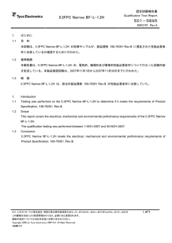
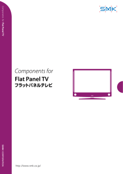
JNPS‐1029, PD-0063
製品仕様書
Product Specification
3M
印
Power Clamp
ボードマウント ヘッダー ライトアングルタイプ
356XX-5X53-XX0 PE
3M™
Power Clamp
Right Angle Boardmount Header
356XX-5X53-XX0 PE
APRV.
T.NAGUMO
9/5, 2008
CHKD.
M.FUKUSHI
9/5, 2008
PRPD.
Y.TSUBAKI
9/5, 2008
SUMITOMO 3M LIMITED
Electronic Solutions Division
Technical Department
JNPS-1029, PD-0063
目次/Table of contents
1
適用範囲··········································································································································3
2
機能··················································································································································4
3
適合対象··········································································································································4
4
関連仕様図類 ·································································································································4
5
関連規格類 ·····································································································································4
6
品質特性··········································································································································5
7
包装&表示 ·····································································································································6
8
保管··················································································································································6
9
取り扱い上の注意 ·························································································································7
1
APPLICATION ··································································································································8
2
FUNCTION·········································································································································9
3
COMPATIBLE OBJECT··················································································································9
4
RELATED SPECIFICATION··········································································································9
5
REFERENCE STANDARDS············································································································9
6
QUALITY PERFORMANCE ·········································································································10
7
PACKAGING & IDENTIFICATION ···························································································111
8
STORAGE CONDITIONS ··············································································································12
9
APPLICATION GUIDELINES·······································································································12
JNPS-1029, PD-0063
1
適用範囲
本仕様書は、下記の製品番号体系に記載された製品番号の、Power Clamp ボードマウント
ヘッダー コネクタに適用する。
製品番号体系
356 XX- 5 X 5 3- X X0
PE
めっき仕様
PE:ニッケル下地めっき
接点部 金メッキ 0.5μm 以上
基板側 金フラッシュメッキ
スタンドオフ高さ
0:標準 (0.5 mm)
P:1.7 mm
誤挿入防止キー
A:タイプ A
B:タイプ B
テール長(基板仮固定部品の適合基板厚)
3:2.6mm(t=1.6mm, 1.0mm)
基板取付方法
5:基板仮固定部品付き
形式
1:標準
2:コンドミニアム型
テール形状
5:ライトアングル型
極数表示
05:5 極×1
10:5 極×2
シリーズ
356 : Power Clamp ボ ー ド マ ウ ン ト ヘ ッ ダ ー
コネクタ
製品型番組み合わせは以下の製品型番に適用する。
35605
35605
35605
35605
35610
35610
-
5153
5153
5153
5153
5253
5253
-
A00
B00
AP0
BP0
A00
B00
PE
PE
PE
PE
PE
PE
3
JNPS-1029, PD-0063
機能
2
当該コネクタは、Power Clamp ボードマウント ヘッダー コネクタのひとつとして、雄端子が
幅方向ピッチ 3.0mm、コンドミニアム型の場合には高さ方向ピッチ 9.0mm で並んでおり、その
雄端子と同じ間隔でライトアングルをなす基板半田付け用端子を持つ。更に、2 つのコネクタ
同士を幅方向に 45mm で並べることができる。ただし、シールド対策は施されていない。そして、
Power Clamp ソケット コネクタと嵌合することにより電気信号を授受する機能を発揮する。
適合対象
3
3.1
適合コネクタ
ボードマウントヘッダーコネクタ
ソケットコネクタ
35505 - 6XX0 - X0X
35715 - L010 - X00
35T05 - 6M00 - X0M
35505 - 6XX0 - X0X
35720 - L200 - X00
35T05 - 6M00 - X0M
35605 - 5153 - XX0 PE
35610 - 5253 - X00 PE
3.2 適合基板
スルーホール PWB
基板穴径
:φ=1.3 mm(コンタクトピン用)
φ=2.0 mm(スナップフィット用)
φ=2.0 mm(ボス用、ノンスルーホール)
適合基板厚 :1.6 mm、1.0 mm
PWB 推奨ホールパターンは、関連仕様図類による。
4
関連仕様図類
添付仕様図類 JNPD-1029 による。
5
関連規格類
MIL-STD-202
JEIDA-38-1984
JIS B 3501
4
GF
AK
GF
GF
AK
GF
JNPS-1029, PD-0063
6
品質特性
6.1 定格
項 目
定 格
10.0A MAX. (1 端子通電の場合)
定格電流
7.0 A MAX. (2 端子以上通電の場合)
定格電圧
250V (AC/DC) MAX.
使用温湿度
-20~75oC, 85%RH 以下
6.2 物理特性
( )内の数値は参考値
項目
挿抜力
耐久性
規格
試験条件
挿入力:
1.96N(200gf)/pin 以下
抜去力:
0.49N(50gf)/pin 以上
試験後、接触抵抗変化量
(Δ25mΩ以下)を満足する
事。
弊社適合コネクタとの組合わせによる。
挿抜スピード 5mm/分で測定する規格は
単極当たりの算出値。
準拠規格
(参考規格)
挿抜 50 回
95%以上の濡れ、又はゼロ Sn-3Ag-0.5Cu はんだ使用
JNTM-0039
- ぬれ性評価
:245oC、3 秒浸漬
クロスタイム:3 秒以下
JIS C 0050
- メニスコグラフ法:245oC
試 験 後 、 外 観 的 に 著 し い 浸漬半田:260oC、10 秒、2 回 又は 263oC、
変形のなきこと
3 秒、2 回 まで
*但し、プリヒートは、部品表面温度が
半田耐熱性
JNTM-0040
100oC 以下、60 秒以内
手半田 :390oC、3 秒、2 回まで
試 験 後 、 接 触 抵 抗 変 化 量 振動試験時に瞬断を測定する。
MIL-STD-202F
耐振動性
(Δ25mΩ以下)を満足する(表 1 参照)
201A
事。瞬断1μ秒以下。
50G、11m 秒、X/Y/Z 軸方向。
試験後、接触抵抗変化量
MIL-STD-202F
耐衝撃性
(Δ25mΩ以下)を満足する 各 3 回
213B
事。瞬断 1μ秒以下。
半田付け性
5
JNPS-1029, PD-0063
6.3 電気的特性
項目
耐電圧
絶縁抵抗
瞬断
接触抵抗
規格
試験条件
漏れ電流 1mA 以内で絶縁
破壊が発生しないこと。
1,000MΩ以上
隣接コンタクト間に AC1,000V RMS を
1 分間印加。
隣接コンタクト間に DC600V 印加し、
1 分後、測定する。
試験中に 1μ秒以上の瞬断が 振動試験
発生しないこと。
3M シーケンス 2 試験として実施
初期接触抵抗
抵 抗 測 定 電 流 1mA 、 開 放 電 圧 20mV
50mΩ以下
4 端子法にて測定する。
(弊社適合ソケットとの組合せであり、
コンタクトのバルク抵抗を含む。)
各種環境試験後の接触抵抗 z 3M シーケンス 1/
50 回挿抜→耐湿試験→塩水噴霧試験
変化量
z 3M シーケンス 2/
Δ25mΩ以下
熱衝撃試験→湿度試験→振動試験
z 3M シーケンス 3/
高温寿命試験
z H2S ガスシーケンス /
50 回挿抜→ H2S ガス試験
z 耐久挿抜試験 /
500 回挿抜
*各種環境試験条件は表 1 参照
準拠規格
(参考規格)
MIL-STD-202F
301
MIL-STD-202F
302
表 1:各種試験条件
7
試験項目
試験条件
耐湿試験
塩水噴霧試験
熱衝撃試験
湿度試験
(定常状態)
高温寿命試験
-10~65oC、95%RH、10 サイクル
塩化ナトリウム 5%溶液、35oC、48 時間
-55oC→25oC→85oC→25oC 、5 サイクル
準拠規格
(参考規格)
MIL-STD-202F-106E
MIL-STD-202F-101D
MIL-STD-202F-107G
40oC、95%RH、96 時間
MIL-STD-202F-103B
85 C/ 1,000 時間
MIL-STD-202F-108A
H2S ガス試験
濃度 3+/-1ppm、40oC、70~80%RH、96 時間
JEIDA-38-1984
振動試験
10→55Hz、振幅 1.52 mm 又は 10G、1 分間掃引
X/ Y/ Z 方向各 2 時間
MIL-STD-202F-201A
o
包装&表示
本品は、プラスチックトレイに納め、更にカートンにて梱包された形態で出荷される。
本品のカートンには、次に示す事項が記入されている。
1) 品名 2) 数量 3) 販売会社 4) ロット番号
8
保管
無負荷、温度(-20~75oC)、常湿(40~70%)の室内で、納入時の梱包状態にて保管すること。
6
JNPS-1029, PD-0063
9
取り扱い上の注意
9.1 使用時の負荷に関して
下図の様なコネクタ上面方向には 30N 以上の負荷がかからないように使用すること。
30N
30N
7
JNPS-1029, PD-0063
1
APPLICATION
This product specification details the requirement for the 3M™ Power Clamp Right Angle Boardmount
Header Connector that is described in the following product numbering information.
Product number information
356 XX- 5 X 5 3- X X0
PE
Plating suffix
PE: Ni Underplating
Contact area
: 0.5μm gold MIN.
Tail area
: Au Flash plating
Height of stand-off
0: Standard (0.5 mm)
P: 1.7 mm
Polarizing key
A: type-A
B: type-B
Contact pin tail length
3: 2.6mm
PWB mounting
5: with mounting parts
Type
1: Standard (1 Row)
2: Condominium (2 Row)
Mounting type
5: Boardmount Right Angle
Contact quantity
05: 5 pin x 1
10: 5 pin x 2
Production series
356:Power Clamp Header Connector
The following product number combinations are available:
35605
35605
35605
35605
35610
35610
-
5153
5153
5153
5153
5253
5253
-
A00
B00
AP0
BP0
A00
B00
PE
PE
PE
PE
PE
PE
8
JNPS-1029, PD-0063
2
FUNCTION
The 3M™ Power Clamp Right Angle Boardmount Header Connector has in-line male terminals. There
are one and two row type connectors. Each row has in-line terminal spaced at a 3.0 mm pitch. Rows are
offset by 9.0 mm and run parallel to each other.
Boardmount pins are opposite of the terminal pins and have the same spacing. The connectors can be
placed side by side. Two adjacent connectors will be 45mm in length. The connector is not shielded. The
function of the connector is to electrically connect and mechanically mate with Power Clamp family socket
connectors.
3
COMPATIBLE OBJECT
3.1 Compatible connectors
Boardmount header connector
Socket connector
35505 - 6XX0 - X0X
35715 - L010 - X00
35T05 - 6M00 - X0M
35505 - 6XX0 - X0X
35720 - L200 - X00
35T05 - 6M00 - X0M
35605-5153-XX0 PE
35610-5253-X00 PE
3.2 Compatible PWB
Through hole PWB
Substrate bore diameter : φ=1.3 mm for Contact pin
φ=2.0 mm for Snap fit
φ=2.0 mm for Locating boss as Plain hole
PWB thickness: 1.6 mm, 1.0 mm
Reference drawings for recommended PWB hole patterns.
4
RELATED SPECIFICATIONS
Reference specifications listed in JNPD -1029.
5
REFERENCE STANDARDS
MIL-STD-202
JEIDA-38-1984
JIS-B-3501
9
GF
AK
GF
GF
AK
GF
JNPS-1029, PD-0063
6
QUALITY PERFORMANCE
6.1 Rating
Item
Rating
10.0A Max. (1 terminal only)
Current
7.0A Max. (2 or more terminals)
Voltage
250V (AC/DC) Max.
Temperature
-20oC~75oC , 85%RH Max.
6.2 Physics characteristic
(Numeric value) is reference value
TEST
DESCRIPTION
Insertion:
Insertion &
1.96N(200gf)/pin Max.
Withdrawal Force
Withdrawal:
(Initial)
0.49N(50gf)/pin Min.
Electrical properties shall be
Durability
stable after test.
Wetting: 95% Min. or
Zero cross time:
Solderbility
3 seconds Max.
Connector should not
have any defect portions
after test.
Soldering heat
resistance
Vibration
Shock
TEST CONDITION
REQUIREMENT
RELATED STD.
(Reference)
Tensile speed : 5 mm/min.
Spec. value is estimated by one contact pin.
Insertion & Withdraw 50 times.
Solder: Sn-3Ag-0.5Cu
- Wetting Measurement:
245oC、3 seconds
- Wetting Balance Method:
245oC
Dip soldering:
260oC, 10 seconds, 2 times or
263oC, 3 seconds, 2 times
* Pre-heat Condition:
Temp. of Components
100oC Max.
Duration 60 seconds Max.
Soldering iron:
390oC, 3 seconds, 2 times
JNTM-0039
JIS C 0050
JNTM-0040
MIL-202F-201 A
Electrical properties shall be
Tested during vibration test together (See
stable after test. Discontinuity
table 1)
1μsec. Max.
Electrical properties shall be
MIL-202F-213 B
stable after test. Discontinuity 50G , 11 m sec , 3 cycles, 3 directions (X,Y,Z)
1μsec. Max.
10
JNPS-1029, PD-0063
6.3 Electrical characteristic
TEST
DESCRIPTION
Dielectric
Withstanding
voltage
Insulation
Resistance
Electrical
Continuity
REQUIREMENT
TEST CONDITION
No appearance of arcing and
break down.
Leak current: 1mA MAX
1,000MΩ MIN
Electrical properties shall be
state under test.
Discontinuity 1μsec MAX.
The initial readings are in
milli-ohms.
50mΩ MAX.
Impressed voltage is AC 1,000V RMS
between two adjacent contacts for 1
minute.
Impressed voltage is DC600V between two
adjacent contacts for 1 minute.
Tested during Vibration test together.
RELATED STD.
(Reference)
MIL-202F-301
MIL-202F-302
The low-signal level contact resistance
shall be tested with circuit current of 1mA
and open circuit voltage of 20 mV
maximum.
The termination resistance includes bulk
resistance of contact, and resistance of
solder joints of connectors to circuit boards.
z3M SEQUENCE 1 /
Contact Resistance After evaluation tests readings
Mating(50 cycles)→Moisture→Salt
are the change in resistance
from the initial reading in
splay
milli-ohms.
z3M SEQUENCE 2 /
Thermal shock→Humidity→Vibration
Δ25mΩ MAX.
z3M SEQUENCE 3 /
Temperature life
zH2S GAS SEQUENCE /
Mating (50 cycles)→ H2S gas
zDurability /
Mating (500 cycles)
Table 1:Environmental tests
ITEM
TEST CONDITION
-10 to 65oC , 95%RH / 10 cycles
Salt solution : 5% (NaCl)
Temperature : 35oC
Duration: 48 hours
Thermal shock -55oC → 25oC → 85oC → 25oC/ 5 cycles
Humidity
Temperature range : 40oC
Relative humidity : 95%RH
(Steady state) Duration: 96 hours
Temperature Life Temperature :85oC
Duration :1,000 hours
H2S gas :3 +/-1ppm
Temperature :40oC
H2S gas
Humidity :70~80%RH Duration: 96 hours
Sweep freq. :10~55Hz, amplitude :1.52mm (or 10G)
Vibration
Sweep cycle :1 min, sweep time :2 hours
Sweep directions :X, Y, Z
Moisture
Salt spray
7
RELATED STD.
(Reference)
MIL-202F-106 E
MIL-202F-101 D
MIL-202F-107 G
MIL-202F-103 B
MIL-202F-108 A
JEIDA-34-1984
MIL-202F-201A
PACKAGING & IDENTIFICATION
Parts are packaged in plastic trays. Trays are shipped in a carton.
Carton is labeled with: 1) part number, 2) quantity, and 3) manufacturer name and 4) lot number.
11
JNPS-1029, PD-0063
8
STORAGE CONDITION
-20 degrees to 75 degrees,
Relative humidity 40-70% without condensation.
9
APPLICATION GUIDELINES
9.1 Upward force limitation.
Please do not add more than 30N of force in an upward direction to this connector.
30N
30N
12
JNPS-1029, PD-0063
Important Notice
The information we are furnishing you is being provided free of charge and is based on tests performed at 3M
laboratory facilities. While we believe that these test results are reliable, their accuracy or completeness is not
guaranteed. Your results may vary due to differences in test types and conditions. This information is intended for
use by persons with the knowledge and technical skills to analyze, handle and use such information. You must
evaluate and determine whether the product is suitable for your intended application. The foregoing information is
provided “AS-IS”. In providing this information 3M makes no warranties regarding product use or performance,
including any implied warranty of merchantability or fitness for a particular use.
Warranty; Limited Remedy; Limited Liability.
3M’s product warranty is stated in its Product Literature available upon request. 3M MAKES NO OTHER
WARRANTIES INCLUDING, BUT NOT LIMITED TO, ANY IMPLIED WARRANTY OF
MERCHANTABILITY OR FITNESS FOR A PARTICULAR PURPOSE. If this product is defective within
the warranty period stated above, your exclusive remedy shall be, at 3M’s option, to replace or repair the 3M
product or refund the purchase price of the 3M product. Except where prohibited by law, 3M will not be liable
for any indirect, special, incidental or consequential loss or damage arising from this 3M product,
regardless of the legal theory asserted.
© 3M 2010. All rights reserved.
3M is a trademark of 3M Company.
3M Electronic Solutions Division
Interconnect Products
6801 River Place Blvd.
Austin, TX 78726-9000
www.3Mconnector.com
13
© Copyright 2026 Paperzz