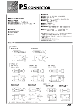
1
2
Components for Flat Panel TV
インタフェースコネクタ
Interface Connectors
4
高周波同軸コネクタ
RF Coaxial Connectors
7
FFCコネクタ
FFC Connector
8
FPCコネクタ
FPC Connectors
8
ACインレット
AC Inlets
10
ACインレット/アウトレット
AC Inlet/Outlet
12
圧着コネクタ
Crimp Connectors
13
φ3.5mmジャック
3.5mm Dia. Jacks
15
ピンジャック
Pin Jacks
15
ジャック板
Jack Boards
16
IRケーブル
IR Cables
17
リモートコントロールユニット
Remote Control Units
18
RFモジュール
RF Modules
21
HDMI Type A Receptacles
HDMI規格タイプA レセプタクル
■ Features
■ 特長
1. Conforms to HDMI standard.
2. Compatible with high speed transmission.
1. HDMI規格に準拠しています。
2. 高速伝送に対応しています。
3. Improving tilting strenght by using a flange of screw stoppers.
4. Both vertical and right angle types available.
3. ネジ止め用フランジにより、こじり強度アップを図っています。
4. バーチカルタイプ、ライトアングルタイプをご用意しています。
● With Flange / フランジ有り
(16.2)
(15)
9
■ P.C. Board Dimension
取付基板参考図
0.55
4.75
0.05 ±0.05
9.5
15.7±0.05
14.5 ±.05
9 ±.03
0.5 ±.03
0.3±0.03
3.6
13
6.18
15.4
12.3
7.5
4.9 ±0.05
Tapping
1.9 ±0.05
F
0.1
CSS5019-06
A
● Without Flange / フランジ無し
■ P.C. Board Dimension
取付基板参考図
6.18
φ1.3 Hole)
ugh
05
±0.
1.55±0.05
1
5.1
9±0.05
0.5±0.03
0.25±0.03
Both sides of
PC board
No.19
No.1
1.55
9
Through hole
14.5±0.05
0.5
0.8±0.05
2±0.1
5.1±0.05
1.5
1.4±0.05
4.4±0.1
M3xP0.5
4.45±0.05
5.7
8.45
7
■ P.C. Board Dimension
取付基板参考図
1
1.4
No.1
9
0.22
プラグ嵌合時のシェルロックパネ最大飛出し量
:0.5以下
● With Flange / フランジ有り
14.5
(Thro
Edge of Board
1.5
2x9.4
13.95
15
No.19
0.5
Pitch
1.9 ±0.05
0.05 ±0.05
1.5
1.5
2.85
1.2
5.7
2.775
7.05
5.95
8.7
15.7±0.05
14.5 ±.05
9 ±.03
0.5 ±.03
0.3±0.03
7.5
4.9 ±0.05
1.9
9
No.1
■ P.C. Board Dimension
取付基板参考図
M3x0.5
CSS5019-1P01F
1.9±0.05
5
● With Flange / フランジ有り
0.5
Pitch
0.2
No.19
Edge of board
1
4.9
±0.0
1
φ1.3
hole
ugh
Thro
1
8
9
14.5
15.7
7.5
4.9±0.05
9.5
3.6
CSS5019-1T01F
15.7±0.05
14.5±0.05
9±0.03
0.5±0.03
0.3±0.03
4.75±0.03
4.75
0.05±0.05
0.55
(16.2)
(15)
9
05
F
1
±0.
CSS5019-07
φ1.3 Hole)
ugh
4.9
(Thro
Edge of Board
1
1
8
9
14.5
15.7
4
● With Flange / フランジ有り
2.5
No.1
Dummy1
Dummy2
0.3±0.05
5.21±0.05 (0.29)
10±0.05
(20)
23
29
Type
Right Angle
Vertical
Part No.
CSS5019-0601F
CSS5019-0611F
CSS5019-0701F
CSS5019-1T01F
CSS5019-1P01F
CSS5019-4K01F
2- φ
15 ±
0
.0
5
(6)
6.7
7.35
3-φ
1.3 ±
0
.05
0.5±0.03
ole
Th
rou
gh
h
(0.55)
0.5
No.1
(7.25)
1.6±0.05
7.9
(t=0.11)
10.5
0.775
No.1
16.1
10
Dummy Terminal
5.21
0.2
No.19
26.5±0.05
14.5±0.05
3.3±0.05
1.9
1.9
1
0.5
2.5±0.05
0.9
0.5
■ P.C. Board Dimension
取付基板参考図
3.3
1
0.5
Th
ro
ug
hh
26.5
14.5
ole
2±0.05
CSS5019-4K01F
M3X0.5
Tap Spec
Tapping
Self Tap
—
Tapping
Tapping
Tapping
Flange
With
With
Without
With
With
With
Screw Height
—
—
—
9.5mm
9.0mm
7.9mm
21P RGB Connector
21P RGB コネクタ
CSS5021-9C01F
23.3
23.8
21.5
21
9×3.81=34.29
No.1
3 10.5
No.21
No.20
2-φ2.5
3.81
10×3.81=38.1
58.5
66
No.2
0.8
3.81
9×3.81=34.29
43.2
58.5
USB Socket A Type ( Vertical Low Profile)
縦型USBソケットAタイプ(低背タイプ)
6-1.065
12.5
7
2
10.5
3-3.8
5.12
CSS5004-1F□□F
Pin NO.1
Pin NO.4
■ P.C. Board Dimension (t=1.6)
取付基板参考図
5
4-A
(14.7)
□□
01
04
A
2.8
3.8
5
6-R0.6
2
7
13.14
(Connector Mount View)
1.3
1.9
0.9
2.88
4-∅
3-1.3
3-2.3
H=10.5mm
2.6
1.905
11.5
3.81
5.08
8.5
.1
0
+0
5×3.81=19.05
+0
.1
0
10×3.81=38.1
2
18.75
20.4
2-φ
1.
-φ
A
3-φ
21
A
A
2.1
11.9
■ P.C. Board Dimension
取付基板参考図
+0.2
0
A
5.08
16.5
3.81
D Terminal Connectors
D端子コネクタ
■ Features
1. Conforms to RC-5237 JEITA standards (D terminal connectors for digital broadcast
video signals, Y, Pb and Pr).
2. Use of bellows type contacts assures a high level of reliability and mating
performance.
3. Choice of a straight or right angle and small type is available for connection.
4. A latch-lock mechanism avoids unintended disconnection.
■ 特長
Flange
11
12
13
14
1. JEITA RC-5327「デジタル放送映像信号用(Y, Pb, Pr)接続用D端子コネクタ」に
準拠しています。
2. ベローズタイプコンタクトを使用し、高信頼性、高嵌合性を保証しています。
3. 端子形状はストレート、ライトアングルを用意し、それぞれ小型、薄型のレパート
リーを取り揃えています。
4. 不用意な離脱を防ぐ、ラッチロック機構付です。
Screw
Without
With
Without
With
M3 tapping
M2 tapping
26
1.27X6=7.62
14-0.5
7.2
11.5
8.5
(12.3)
4-2
4-1
4-3.8
● Straight Type (Small and Low Profile Size) : CSS5014-2K01F
2π2
12.62
No.7
Pin
No.1
6.3
7
9.4
12
.5
11.8
1.7
(17.14)
19.54
29.54
No.14
● Straight Type (Small Size) : CSS5014-07
No.8
9.62
23.64
F
● Right Angle Type (Small Size) : CSS5014-08
F
5.2
3.5
4.8
18
1.5
2-
2.5
No.14
No.14
9.6
23.64
Pin No.1
7
9.4
12
6.3
No.7
2.5
10
7
Pin No.1
9.4
12
12.62
6.3
No.7
2-
5.2
17.14
30
36
17.14
30
12.62
3
9
3.5
4.8
15
15
1.27 6 7.62
14-0.5
9.6
23.64
No.8
11
3-3
No.8
6
RF Coaxial Connectors / 同軸コネクタ
TC-5 Series(6GHz)
■ Features
■ 特 長
1. 1.4mm height when mated.
2. Mounting area saving design (receptacle) measuring only
1.95mm × 1.85mm. (Weighting 0.005g.)
3. A teflon insulafor 0.81mm dia. coaxial cable on standard
1. プラグとレセプタクルの嵌合高さは、1.4mmです。
2. 基板占有面積(レセプタクル)は、1.95mm × 1.85mmと超小型、
省スペースです。
(重さ0.005g)
3. プラグのケーブルは、外径φ0.81のテフロン同軸ケーブルを標準
としています。
Plug : CRC9001-4301F
Socket : CRS5001-3101F
0.825
2.7
(φ0.81)
2
(1.85)
0.85
0.85
0.7
1.95
1.65
1.4
0.25
0.7
1.15
(0.45) 0.15
0.7
0.3
TC-7 Series (3GHz)
■ Features
■ 特 長
1. Low profile of 1.0mm height when the receptacle and
plug are mated.
2. Small and area-effective receptacle of 1.85mm × 1.95mm
mounting area.
3. Very low mass of 0.004g with the receptacle and 0.013g
with the plug (excluding a coaxial cable).
4. Available two types of cables.
· 0.46mm dia. micro cable is easy to draw in side
· equipment.
· 0.66mm dia. cable shows high performance as antenna.
1. レセプタクルとプラグの嵌合高さ1.0mmの低背タイプです。
2. レセプタクルの基板占有面積は1.85mm × 1.95mmの超小型、
省スペースです。
3. 製品質量はレセプタクル0.004g、プラグ0.013g(同軸ケーブル
は除く)と軽量です。
4. 適合同軸ケーブルには、
機器内の引き回しを容易にするφ0.46mm極細
ケーブル、アンテナ性能を配慮したφ0.66mmケーブルを準備して
います。要望によりφ0.46mm、φ0.66mmの選択が可能です。
Plug : CRC9001-□□□□F
1.95
0.85
2.7
1.94
0.85
0.8
0.3
0.15
(1.85)
0.8
1.65
(π0.46 or π0.66)
Socket : CRS5001-4101F
□□□□
6101
7101
0.6
0.2
0.65
π1.35
Applicable Cable
TS-9 Series (3GHz)
■Features
■特 長
1. An externally connectable right angled coaxial connector
with switch (3.2mm height).
2. A wide frequency coverage of DC up to 3GHz with excellent
frequency characteristics.
3. Half locking structure with the plug is providing a positive
clicking feeling.
4. Embossed taping for automatic mounter.
1. 外部接続が可能なライトアングルタイプのSMT対応スイッチ付
同軸コネクタです。(高さ : 3.2mm)
2. 仕様周波数範囲はDC∼3GHzをカバーし、周波数特性が良好です。
3. プラグとの嵌合はハーフロックとなっており、クリック感のある
操作性があります。
4. エンボステープによる自動実装に対応しています。
Plug : CRC9001-5301F
φ2.5
3.2
1.95
7
3.85
φ3.65
φ4.1
φ4.4
(φ2.0)
3.0
2.7
0.4
1.0
3.8
(6.85)
2.6
0.4
Receptacle : CRS5001-3702F
4.9
7.0
11.7
FPC・FFC Connectors / FPC・FFCコネクタ
EN-5D Series
■Features
1.Capable of high speed serial transmission including LVDS, TMDS (HDMI), same
performance as micro coaxial.
2. Applicable FFC uses a double-surface FFC having a signal layer and GND layer
and the impedance matching is easy.
3. The contact is separated into signal use and ground use, and excellent shielding
characteristics are realized by connecting to the FFC ground layer.
4. Non-ZIF structure provides the simple insertion of FFC.
5. With a structure to prevent improper FFC insertion and failing off.
■特長
1. LVDS、TMDS(HDMI)をはじめとする高速シリアル伝送に適応し極細線同軸と
同等性能です。
2. 適合FFCは信号層とグランド層を有している両面FFCを使用し、インピーダンス
マッチングが容易です。
3. コンタクトは信号用とグランド用が独立しており、FFCグランド層と接続させる
ことで優れたシールド特性を実現します。
4. コネクタはNon-ZIF構造でFFC挿入は1アクションで簡単に行えます。
5. FFC挿入確認機構、抜け止め防止機構付きです。
● CFF97
-0101F
A+11=B
(n-1)X0.5=A
0.3
0.5
6
No. of Pins
2
C
D
0.6
Z
41
41
51
51
Z
EF-5D Series
■Features
1. Compatible with high speed serial transmission such as LVDS and TMDS (HDMI).
2. Differential impedance matches 100Ω.
3. Double-faced FPCs are used and strengthened the signal and ground layers.
An EMI Solutions is taken by having the connector featuring our original
double-contact structure cause the FPC ground layer to contact. The signal
side can be tailored to any pin assignment.
■特長
1. LVDS、TMDS(HDMI)をはじめとする高速シリアル伝送に適応しています。
2. 差動インピーダンス100Ωにマッチングしています。
3. 適合FPCは両面FPCを使用し、信号層とグランド層を持ち強化しています。
独自の両面接触構造のコネクタにより、FPCグランド層を接触することで、
EMI対策にも配慮しています。また、信号面はあらゆるピンアサインに自由に
対応可能です。
0.35
● Right Angle Type : CFP87
-0101F
● Vertical Type : CFP88
-0101F
B
B
6.1
1
0.5
(n-1)X0.5=A
Open
A
C
Open
C
6
0.35
0.5
Lock
Lock
8
FPC・FFC Connectors / FPC・FFCコネクタ
EF-51 Series
■Features
1. Our original front flip lock structure ensures multi pins products of high level
contact reliability.
•The structure which relieves the load from the cover when the FPC is
•locked will prevent detachment or breakage of the cover.
•There are no restrictions to the direction in which the FPC can be laid.
2. By turning the cover, an FPC/FFC can be connected easily with only a
small force.
■特長
1. 独自のフロントフリップロック構造で、多極においても高接触信頼性を
確保しています。
・FPCロック時カバーに負荷が掛からない構造により、カバー外れ・壊れ
を防止します。
・FPC引き回し方向に制限がありません。
2. カバー回転により、簡単かつ軽い力で確実なFPC/FFC接続作業が可能です。
(A+5.0)=B
-0350F
0.15
4.9
● CFP89
(A+5.7)=C
2.5
0.5
(A+2.35)=D(FPC/FFC挿入口)
(
-1)X0.5=A
Scale10:1
EF-52 Series
■Features
1. Our original front flip lock structure ensures multi pins products of high level
contact reliability.
•The structure which relieves the load from the cover when the FPC is
•locked will prevent detachment or breakage of the cover.
•There are no restrictions to the direction in which the FPC can be laid.
2. By turning the cover, an FPC/FFC can be connected easily with only a
small force.
■特長
1. 独自のフロントフリップロック構造で、多極においても高接触信頼性を
確保しています。
・FPCロック時カバーに負荷が掛からない構造により、カバー外れ・壊れを
防止します。
・FPC引き回し方向に制限がありません。
2. カバー回転により、簡単かつ軽い力で確実なFPC/FFC接続作業が可能です。
-0450F
0.5
A+5.4=B
(XX-1)X0.5=A
0.15
6.85
● CFP89
A+6.3=E
A+2.7=C
0.25
2.5
A+1.27=D
(G-0.25)
G
9
6.85
0.05
1.85
4.95
0.7
FPC Connectors / FPCコネクタ
FP-5F Series
■Features
1. Our original front flip structure ensures multi-pole products of high level
contact reliability.
•The structure which relieves the load from the cover when the FPC is locked
will prevent detachment or breakage of the cover.
•There are no restrictions to the direction in which the FPC can be laid.
■特長
1. 独自のフロントフリップロック構造で、多極においても高接触信頼性を確保
しています。
・FPCロック時カバーに負荷が掛らない構造により、カバー外れ・壊れを
防止します。
・FPC引き回し方向に制限がありません。
(n-1)×0.5=A
1
0.5
Pln No.1
4.1
-0150F
3.3
● CFP50
A+1.05=B
A+2.0=C
2.15
Contact
(6.5)
4.9
1.3
A+3.7=D
0.9
0.9
3.9
Lock
Open
AC Inlets / ACインレット
CCT2302-
F
→
→
Polarized Serial No.
■ Features
1. About 27% smaller than our previous equivalent products.
2. Conforms to the IEC320-1 standards, sheet C8.
3. Also available with reinforcement hardware and cover.
4. Conforms to safety requirements of European and American standards.
■ 特長
1. 体積は、当社従来品に比べ約27%小型化しました。
2. 国際規格IEC320-1スタンダード・シートC8に準拠しています。
3. 補強金具、カバー付き品を用意しています。
4. 欧米各国の安全規格を取得しています。
Variation / バリエーション
Polarized
極性
CCT2302-07
Cover / カバー Metal Fixture / 固定金具
Shape / 形状
F
07
01
○
○
11
○
×
21
×
○
31
×
×
Approval Standards:
UL
CSA
SEMKO
NEMKO
DEMKO
FIMKO
VDE
CCT2302-08
F
CCT2302-09
F
08
09
Catalog No. : II24
10
AC Inlets / ACインレット
CCT2102-1051F
■ Features
1. Conforms to IEC60320-1, standard sheet C8.
2. Conforms to safety requirement of European and American standards.
3. Expanded design freedom due to a wire winding design.
■ 特長
1. 国際規格IEC60320-1スタンダード・シートC8に準拠しています。
2. 欧米各国の安全規格を取得しています。
3. ワイヤー絡げタイプで、設計自由度に貢献します。
4.2
2.8
16.5
8.6
16
8.2
Approval Standards
UL
60°
CSA
CCT2302-1101F
4.8
Catalog No. : II16-3
9.1
10
6.8 12.5 3
φ2.36
VDE
■ Features
1. Conforms to IEC60320-1, standard sheet C8.
2. Conforms to safety requirement of European and American standards.
■ 特長
1. 国際規格IEC60320-1スタンダード・シートC8に準拠しています。
2. 欧米各国の安全規格を取得しています。
23
20
16.5
8.6
7
FIMKO
1125-1
Catalog No.
Catalog No. : II25-1
11
60˚
3.5
SEMKO
w
3.2
NEMKO
15
DEMKO
14
10
TEXTURE
PHOTO ETCH
RO
.5
6
UL
CSA
4-R
O.
5
18.5
13.5
12
8.2
4.2
Approval Standards
1.5
AC Inlets / ACインレット
CCT2302-1302F
■ Features
1. Conforms to IEC60320-1, standard sheet C8.
2. Conforms to safety requirement of European and American standards.
■ 特長
1. 国際規格IEC60320-1スタンダード・シートC8に準拠しています。
2. 欧米各国の安全規格を取得しています。
23
20
16.5
8.6
7
NEMKO
VDE
FIMKO
SEMKO
6
1125
3.5
CSA
3.2
DEMKO
14
10
15
UL
1.5
18.5
13.5
12
8.2
4.2
Approval Standards
Catalog No.
60˚
Catalog No. : II25
AC Inlet /Outlet
CCT9304-0401F
ACインレット / アウトレット
■ Features
1. These inlets are independent type from the printed circuit board.
2. Can be fixed to the chassis with two tapping screw.
3. The AC inlet and AC outlet are combined in one unit to reduce manpower
requirements for mounting them to the P.C. Board or fixing to the chassis.
■ 特長
1. プリント基板に自立する構造です。
2. シャーシに2ヶ所のタッピングねじで固定ができます。
3. ACインレットとACアウトレットが一体化されており、プリント基板へのマウント
及びシャーシ止めの工数削減が図れます。
Applicable Plug
31
28
23
Catalog No. : IR47-1
21.75
18
1.5
CSA
25.7
7.25
Approval Standards
UL
2.5
35.5
38.5
8.6
12
Crimp Connectors / 圧着コネクタ
2P Crimp Connector / 2P圧着コネクタ
■ Features
1. A 2P crimp connector of thin configuration.
2. Low profile of 1.75mm height when mounted.
3. Space saving design including the mounting area, with hold-down provided at connector
center.
4. Housing provided with improper insertion prevention guide on the right, left and center, and
also with a locking structure on the right and left for prevention of dropping off caused by
vibration and shocks.
5. Apply an AWG26, 1mm dia. (jacket inclusive) outside diameter cable.
■ 特長
1.
2.
3.
4.
薄型の2P圧着コネクタです。
基板実装高さは1.75mmと低背です。
コネクタ中央にホールドダウンを設置し、実装パターンを含めた省スペース設計です。
ハウジングは、左右及び中央に誤挿入防止ガイドを設置、左右に振動・衝撃による抜け
防止用ロック機構を備えています。
5. 被覆外径φ1.0mm、AWG26電線の圧着が可能です。
● Socket : CPL2102-0101F
● Plug : CPL2302-0101F (Terminal : CTA5126-1101F)
0.9
1.6
1.7
5.5
5.5
3
5.5
5.4
0.85
4.5
3.05
0.25
0.4
5.55
6.1
4.15
3
0.2
0.7
1
5.2
0.75
1.7
0.75
0.5
0.55
0.8
1.05
0.05
1.75
0.05
0.7
0.4
0.55
5.25
0.1
0.5
6.1
PinNo.
0.1
PinNo.
3P Crimp Connector / 3P圧着コネクタ
■ Features
1. A low profile connector made productive by provision of a top-entry type mating structure
where a crimping connector is inserted in a vertical direction, with wire emerging
horizontally.
2. 2.2mm height when mated.
3. With the contact section structured for a pin to be put between dimples, ensured stable
contact performance against vibrations, tilting uses and fretting.
4. Easy but ensured terminal insertion due to adoption of a spring-like housing lance structure.
■ 特長
1. 上方向から圧着コネクタを挿入するトップエントリー嵌合で作業性を考慮し、電線の引き出
し方向は横方向とした低背コネクタです。
2. 嵌合高さは、2.2mmです。
3. 接触部はディンプルでピンを挟み込む構造とし、振動やこじり、微摺動に対し安定した接触
状態を保持します。
4. バネ性をもったハウジングランス構造の採用によりターミナル挿入が容易で確実な装着が可能です。
● Plug : CPL5503-0101F
1.3
PinNo
0.45
2.4
1.2
0.45
0.25
0.95
PinNo
0.2
4.85
13
4.2
4
MAX0.15
3
3.95
1.95
1
1.95
4
5.4
1.35
3.45
1.9
0.6
5.4
2.4
0.4 1.2
3.5
3.2
0.7
0.45
2
1
0.25
● Socket : CPL1103-1601F (Terminal : CTA1126-1450F)
Crimp Connectors / 圧着コネクタ
HP Series (1.25mm Pitch)
■ Plug(SMT Type)
CHP25□□-0101F
CHP27□□-0101F
A+3.0
(n-1) 1.25=A
3.5
3.5
A+3.0
(n-1) 1.25=A
1.25
1.25
● Terminal Part No. : CTA1126-0501
Applicable Wire Size : AWG26 to 32
■ Socket
■ Plug(DIP Type)
A+3.0=B
(n-1)×1.25=A
1.25
2.02
3.9
0.9
0.32
3.1
2.3
1.25
(n-1)x1.25=A
A+3.0=B
1.4
2.3
1.25
4.2
4.05
2.7
CHP17□□-0101F
5.8
2.3
3.5
CHP15□□-0101F
3.1
A+3.0=B
Right Angle Plug
1.08
CHP11□□-0101
Straight Plug
4.9
3.85
5.45
4.9
(n-1)×1.25=A
Straight Plug
Right Angle Plug
EP Series (1.5mm Pitch)
■ Plug(SMT Type)
CGP45□□-0101F
CGP47□□-0101F
A+2.8
(n-1) 1.5=A
Pitch1.5
A+2.8
(n-1) 1.5=A
Pitch1.5
4.45
3.75
■ Plug(DIP Type)
CGP16□□-0101F
2.7
4
0.4
1.5
4.5
A 2.2
7.95
5.25
6.7
1.3
0.4
2.7
3.35
5.3
4.8
CGP17□□-0101F
A+2.8=B
(n-1)x1.5=A
1.5
1
2.7
2.2
A+2.8=B
(n-1)x1.5=A
1.5
A+2.6=B
(n-1)x1.5=A
1.5
3.5
CGP12□□-0101
0.2
Right Angle Plug
Straight Plug
6.75
5.25
■ Socket
5.75
● Terminal Part No. : CTA1126-0101
Applicable Wire Size : AWG26 to 32
● Terminal Part No. : CTA1126-1001
Applicable Wire Size : AWG24 to 26
5.75
7.75
6.0
4.45
Straight Plug
Right Angle Plug
14
3.5mm Dia. Jack
φ3.5mmジャック
LGT8509-0100F
8
4.5
8.5
φ8
10
Circuits
回路
2
4
3
1
φ3.6
2×1×2
3.9
3.9
φ3.5 +0.2
0
4
2×2×0.9
3
2
4.15
4.2
Discrete Type
1
ディスクリートタイプ
4.15
■ P. C. Board Dimension
取付基板参考図
2×φ1.3 +0.1
0
6.5
Pin Jacks / ピンジャック
Thin Type Jack Board, AP-3T・V Series (Vertical)
■ Features
■ 特長
1. Thin type of 8.5mm height when mounted (only 43% of our
previous equivalents).
2. Provides a wide range of products such as 5P and 6P,
10P of pin jack type, and 6P+2S terminals and 9P+3S
terminals.
3. Customizable to customer requirements such as the
addition of a switch and provision of other pin quantities.
4. Reduction of digital noise due to the provision of a shield
plate at the front part of the pin jacks.
1.基板面高さ8.5mmの薄型タイプです。
(当社従来品比43%減)
2.5P、6P、10P、6P+2S端子、9P+3S端子と、豊富な
レパートリーを揃えています。
3.スイッチ機能の有無、極数選択など、各種カスタム仕様に
対応可能です。
4.ピンジャックのフロント部にシールド板を設けており、
セットのデジタルノイズ対策に貢献します。
LAP5000-2301F
7
14
7
Color Layout
8.5
φ10.5
Y/C
(S)
Yellow
White
White
Red
Red
φ8.3
14
7
14
59
7
16
Yellow
Circuits
(With Switch)
7
7
φ3.4
With Switch
(Break)
0.4
2-φ2.4
(DEPTH:7.6)
h
f
j
5
8.5
2
3.5
5.5
a
b
Pin Jack
22.5
LAP5000-2401F
g
e
i
5.5
i
a d c
Pin Jack
e f
g h j
Y/C(S-Video)Socket
Color Layout
14
7
14
A
8.5
φ10.5
Y/C
(S)
φ3.4
Yellow
A
White
White
White
Red
Red
Red
φ8.3
With Switch
(Break)
7
Circuits
(With Switch)
7
φ3.4
14
7
14
59
7
16
7
4-φ2.4
(DEPTH:7.6)
0.4
14
i
g
e
h
f
j
5
8.5
5.5
2
36.5
15
b
a d c
Pin Jack
a
Pin Jack
i e f g h j
Y/C(S-Video)Socket
Pin Jacks / ピンジャック
Thin Type Jack Board, AP-3T Series (Right Angle)
■ Features
■ 特長
1. 7.5mm deep, 55% reduction from our previous equivalent
products (when compared to our 13.7mm deep product).
2. A wide range products of 2P, 3P, 3P+S terminal, 5P and
6P+S terminal.
3. Switch optionally available with S terminal, pin jacks, and
all terminals.
4. Contact timing in sequence of ground, then other
contacts, for reduced noise.
1. ジャック板奥行き7.5mmを実現、従来品比55%の薄さを
実現しました(弊社従来品奥行き13.7mmと比較)。
2. 2P・3P・3P+S端子・5P・6P+S端子と豊富なレパート
リーを揃えています。
3. S端子、ピンジャック、全ての端子にスイッチ対応可能
です。
4. 接触タイミングをアース・グランド→コンタクトの順番
としており、セットのノイズ軽減に貢献します。
LAP5300-0110F
White
Yellow
φ2.4
Red
59.5
14
18
3.5
14
6.5 φ3.4
14
9.5
7.5
5.2
A1
A2
B1
φ12.5
14.5
8
7
φ8.3
2
4.5
Color layout
4.3
4
14
: With Switch
Circuits
(With Switch)
d
B1
A1, A2
b1
g
e
i
i
h
g
f
e
d
b1
c1
a
h
f
a
Y/C (S-Video) socket
Pin jack
Jack Board / ジャック板
Pin Jack Module with Optical Connector
光コネクタ付ピンジャックモジュール
■ Features
■ 特長
1. Putting every type of input/output signal terminal together
on jack boards, such as a pin jack, S terminal and optical
connector, saves equipment design time and improves
assembling efficiency.
2. A shutter featured with the optical section.
3. This product is available on a customization basis only.
1. ピンジャック、S端子、光コネクタなど、全ての入出力
信号を1つのジャック板に集約することで、セットの設
計工数と組立作業の効率が向上します。
2. 光コネクタ部はシャッター付構造です。
3. カスタム対応が可能です。
LAF1011-0102F
15
8.2
1.2
8.2
d1 Vin
d2 VCC
d3 GND
4.5
13.5
4
6
3.5
18.2
11.8
Circuits
(Without Switch)
27.5
14.5
ø2.4
ø10
ø8.3
11
a
Optical
Receiver
b
Pin Jack
1P Pin Jack
+Optical Connector
16
IR Cables / IRケーブル
● An infrared cable whereby separate equipment such as set-top boxes, VCRs, etc. can be remotely controlled from
the master equipment.
● セットトップボックスやVCR等セット本体から他の機器を赤外線でコントロールするための赤外線ケーブルです。
SSR-IR02
17.5
10.5
CHINA
32.6
1
14.2
Sleeve
51
3.5
9
19.6
4 33
18.5
Tip
1500
SSR-IR03
CHINA
1500
Belt
12
50
π 3.5
Monaural plug :
9.5
(100)
SSR-IR04
24
12
8.5 5
35
17.5 10.5
CHINA
5.2 6
π5
13
4
4
Belt
(100)
17
π 3.5
Monaural plug :
Remote Control Units / リモートコントロールユニット
Standard Type / 標準リモコン
SSR-CAV26
●
It is applicable between 14 keys and 26 keys.
●
14キーから26キーに対応可能です。
MALAYSIA
26 Key Function
Battery (UM-4, “AAA”, R03)
21.5
22.4
21.2
6.75
12.5
6.75
15.5
φ7.6
37.5
27
16.5
10.8
0
21.6
6
5.4
10.8
16.5
22.75
29.5
39
5.4
48.5
63.1
35.5
135
φ8
58
6.6
78
82.59
Standard remote control featuring a
back lighting function.
●
照光機能付標準リモコン
15.5
●
17.5
23
6.75
20.8
34
SSR-32ML
●
It is applicable to 30 key type and 31 key type.
●
30キータイプと31キータイプも対応可能です。
MALAYSIA
φ5
32 Key Function
Battery (UM-4, “AAA”, R03)
4.75
4.25
11
33
12.φ9
2.φ8
50
3xP10=30
28
20
20
2.4
14
25.5
23
37.5
49.5
61.5
16.3
31
61.5
.5
R1.5
R1
6
90.75
105.5
113.5
121
128.5
3
3
0.5
23.5
9
13
0.5
20
10.9
4.φ7
155
72
10.5
30
18
Remote Control Units / リモートコントロールユニット
Standard Type / 標準リモコン
SSR-STD33
CHINA
33 Key Function
Battery (UM-3, “AA”, R6)
22.9
54
35
110
10
11.5 11.5 9.6 10.5 11 11 11 12 8.510.5
135
1.6
10 10 10
25
46
50
25.9
SSR-36
6.3
CHINA
36 Key Function
Battery (UM-3, “AA”, R6)
12.6
44
38.79
22.4
21.5
24.2
126.63
144.33
3゚
φ8
8.5
21.5
25.3
2.765
8
0
19.3
20.9
27.6
29.2
35.3
36.6
φ4.2
17.365
19
20
106.7
25.1
φ24.721
φ14.105
38.294
10.972
45
φ3.7
50.1
42.5
34.9
27.3
19.7
68.391
68.39
16.785
70.83
4.6
1.2
20
59.7
6.9
12
3
φ7.2
0.499
9
30
Remote Control Units / リモートコントロールユニット
Standard Type / 標準リモコン
SSR-51ML
●
Installation of a slide switch is optional.
●
オプションでスライドスイッチの取り付けが可能です。
MALAYSIA
31.2
27.2
10.4
24.2
193
32.3
30
22
106.75
103.25
90.4
80
71
62
52.5
42.5
32.5
22.5
11.75
200
51 Key Function
Battery (UM-3, “AA”, R6)
0
11.75
24.5
29.2
38
47
56
65.5
93.25
10.5
27.7
31.5
46
53
SSR-55
CHINA
●
オプションでスライドスイッチの取り付けが可能です。
25.2
10.3
1.5
38
30
35.1
8.8 8.5 12.4 11.9
50
43
28.8
26.8
11.5
Installation of a slide switch is optional.
5.2
55 Key Function
Battery (UM-3, “AA”, R6)
●
28.5
25.6
210
8.5 8 8 10.4 22.8
203
10.7
28.4
25.5
27
28.8
20
RF Module / RFモジュール
ZigBee® RF4CE Compatible RF Module for Remote Control Units
リモコン用ZigBee® RF4CE対応RF (無線) モジュール
■Features
1. The easily structuring of PAN with the remote control as its core is possible
using the RF omni-directionality feature (N-to-N application is possible).
2. Conforms to ZigBee® RF4CE Specification Version 1.00.
3. The employment of radio communication method using 2.4GHz IMS band
provides equipment with worldwide applicability and contributes to the
standardizing of the equipment.
4. The standby-mode and intermittent reception features conserves electricity
consumption.
5. DS-SS employed for modulation system provides high-resistance to noise and
interference.
6. Module is certified according to the Japanese Radio Law, FFC and CE. Upon
successful acquisition, RF applications do not require individual
acquisition of qualification for such standards, which creates shorter lead time
for equipment development and lower costs.
7. Compatible with decoded output of various IR communication formats, no
change in equipment of application software is necessary, other than
substituting previous IR receivers with this module. Equipment designing will
thus be simpler.
■特長
1. RFの特性である無指向性を活かし、容易にリモコンを中心としたPANの構築
が可能です(N対N対応が可能)
。
2. ZigBee RF4CE Specification Version 1.00に準拠しています。
3. 2.4GHz IMSバンドを使用した無線通信方式の採用により、ワールドワイド対応と
なっており、セット設計の標準化に貢献します。
4. スタンバイモードおよび間欠受信により省電力化に対応します。
5. 変調方式にDS-SSを採用し、ノイズに強く、高い混信防止性能を持ちます。
6. モジュール単品で日本電波法、FCC、CEの認証を取得。セットとしての
RFに関する認証取得作業が不要となり、セットの開発時間の短縮や認証費用の
削減に貢献します。
7. 各種赤外線通信フォーマットのデコード出力に対応しており、既存の赤外線
受光器を本モジュールに置き換えるだけで、セット側のアプリケーションソフトの
変更を必要としないため、セット設計を容易にします。
1
17
1
8
2.5
42
.2
3.15
π3
Max. 5
(6.3)
(Max. 4)
Max. 1
(17.6)
21
LEDバックライトへの提案品目
Promoting Products for LED Back Light
1. 基板間接続用コネクタ
Board to Board Connector
2 . 2P 圧着・圧接コネクタ
2P Crimp / ID Connector
For reference only
※ Image
※ LED バックライトイメージ(一例)/ Image of LED back light( for example )
1. 基板間接続用コネクタ
Board to Board Connector
2. 2P 圧着・圧接コネクタ
2P Crimp / ID Connector
22
© Copyright 2026 Paperzz