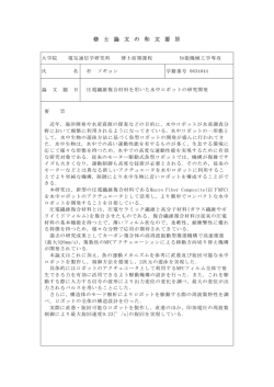
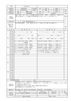
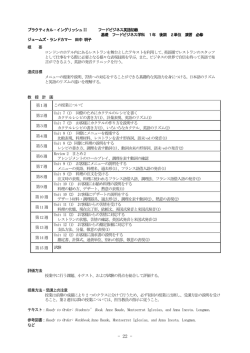
OPTICAL TALK SET
光トークセット
MODEL 415/430/450/450XL
INSTRUCTION MANUAL
取扱説明書
HR1028-13J-11/110906
** TABLE OF CONTENTS **
1. GENERAL INFORMATION ・・・・・・・・・・・・・・・・・・・・・・・・・・・・・・・・・・・・・・ 1
2. SPECIFICATIONS・・・・・・・・・・・・・・・・・・・・・・・・・・・・・・・・・・・・・・・・・・・・・・ 1
3. OPERATING INSTRUCTIONS ・・・・・・・・・・・・・・・・・・・・・・・・・・・・・・・・・・・ 2
3-1.
3-2.
Descriptions ・・・・・・・・・・・・・・・・・・・・・・・・・・・・・・・・・・・・・・・・・・・・・ 2
Preparation ・・・・・・・・・・・・・・・・・・・・・・・・・・・・・・・・・・・・・・・・・・・・・・ 4
3-3.
Operation・・・・・・・・・・・・・・・・・・・・・・・・・・・・・・・・・・・・・・・・・・・・・・・・ 5
Three Party Communications ・・・・・・・・・・・・・・・・・・・・・・・・・・・・・・ 6
3-4.
4. PRECAUTIONS ・・・・・・・・・・・・・・・・・・・・・・・・・・・・・・・・・・・・・・・・・・・・・・・・ 6
5. OPTIONAL ACCESSORIES ・・・・・・・・・・・・・・・・・・・・・・・・・・・・・・・・・・・・・ 7
6. REPAIR SERVICE INFORMATION ・・・・・・・・・・・・・・・・・・・・・・・・・・・・・・・ 7
◆◆ 目
次 ◆◆
1. 概
要
・・・・・・・・・・・・・・・・・・・・・・・・・・・・・・・・・・・・・・・・・・・・・・・・・・・・・・ 9
2. 仕
様
・・・・・・・・・・・・・・・・・・・・・・・・・・・・・・・・・・・・・・・・・・・・・・・・・・・・・・ 9
3. 操 作 方 法 ・・・・・・・・・・・・・・・・・・・・・・・・・・・・・・・・・・・・・・・・・・・・・・・・・・・・ 10
3-1. 各部の説明と操作
・・・・・・・・・・・・・・・・・・・・・・・・・・・・・・・・・・・・・・・・・・ 10
3-2. 準
備
・・・・・・・・・・・・・・・・・・・・・・・・・・・・・・・・・・・・・・・・・・・・・・・・・・・ 12
3-3. 通
話
・・・・・・・・・・・・・・・・・・・・・・・・・・・・・・・・・・・・・・・・・・・・・・・・・・・ 13
3-4. 連結通話(3 者間通話)
・・・・・・・・・・・・・・・・・・・・・・・・・・・・・・・・・・・・・ 14
4. 取扱上の注意 ・・・・・・・・・・・・・・・・・・・・・・・・・・・・・・・・・・・・・・・・・・・・・・・・・・ 14
5. オプション ・・・・・・・・・・・・・・・・・・・・・・・・・・・・・・・・・・・・・・・・・・・・・・・・・・・・・ 15
6. アフターサービス ・・・・・・・・・・・・・・・・・・・・・・・・・・・・・・・・・・・・・・・・・・・・・・・・ 16
1. GENERAL INFORMATION
The 415, 430, 450 and 450XL Optical Talk Set are designed to used for
communications between crews in construction and maintenance of SM fibers.
Full duplex communication is possible over an SM fiber.
Model 415 :A 1310nm laser diode is built in each unit
Model 430,450,450XL :Two units with different wavelengths, Unit A and B, are
provided as a pair together. The unit A has a 1310nm
built-in laser diode and a 1550nm laser diode is built
in the unit B.
2. SPECIFICATIONS
MODEL
Wavelength
415
430
1310nm
450
A : 1310nm,
Communication
system
Modulation
Voice band amplitude modulation
Fiber type
Single mode fiber SM10/125
Connector type
SC (standard), FC, ST, DIN (optional)
Dynamic range
Buzzer
(Dynamic range)
450XL
B : 1550nm
Full duplex (wavelength multiplex)
≧ 35dB
≧ 45dB
≧ 55dB
≧ 60dB
2kHz (the main unit), 150Hz (the earphone)
(≧ 35dB)
(≧ 35dB)
(≧ 40dB)
Temperature
-10~50℃ (80%RH or less, non-condensing)
Power supply
UM-3 (AA) battery 4 pcs, or AC main supply
Battery life
Approx. 15 hours
Dimensions
65(W)×175(H)×35(D)mm
Weight
350g (including batteries)
Accessories
Headset (with conversion-plug)
2
Connector adapter
2
UM-3 (AA) battery
8
Case for main units
2
Instruction manual
1
1
(≧ 45dB)
3. OPERATING INSTRUCTIONS
3-1. Descriptions
(499-HS)
(499-HS5)
b
a
c
d
b
d
e
a
① Power switch
STBY
(Stand-by)
The power is on and the unit is ready to receive signals.
The buzzer sounds when receiving a CALL signal. This mode
consumes 50% less power than the ON mode below.
ON
The unit is ready to receive and transmit signals.
OFF
The power is off.
② Mode indication lamp
The green lamp lights up when the unit is in the STBY mode, and when in the
ON mode, the lamp turns to red. If the lamp starts to blink, it indicates that
the battery voltage is down, so that the all batteries should be changed.
③ CALL key
This key is used to call your partner.
called with the buzzer.
Press this key and your partner will be
2
④ Sensitivity setting switch (SHORT/LONG)
The sensitivity is set at 2 levels, SHORT and LONG. Select the appropriate
level in accordance with the fiber type and length. For instance, select the
SHORT if the attenuation of the fiber between 2 parties is 10dB or less, and if
the attenuation is more than 10dB, select the LONG.
⑤ Volume control
Control the volume of the headset with this dial. As the unit has voice band
amplitude modulation, the volume should be adjusted according to the
transmission loss.
⑥ Headset jack
Insert the plug of headset or throat microphone (optional) fully in this jack.
not insert or pull out the plug while the unit is powered on.
Do
⑦ Optical input port
Remove the protection cap (⑨). Optical power is input here and output from
here. An SC type connector adapter has been mounted in this port. Other
types of connector adapter are also available.
CAUTION :
CAUTION :
Danger!
Class 1 laser is output from here. Never look directly into
the port or a fiber. Eye damage may result.
The ferrule face inside the port should be kept clean. Dust
on the ferrule face may cause abnormal reflection and affect
normal operation.
⑧ Voice cascade jack
Two units are coupled on to be used as a translator when communicating
among three parties. (See 3-4. Three Party Communications.) Do not insert
or pull out the plug while the units are powered on.
CAUTION : Do not insert the Headset-plug, it may damage the Headset.
⑨ Protection cap
This cap is for eye protection against Class 1 laser.
CAUTION :
Danger!
Never look directly into the optical input port or a fiber while
the unit is on. Invisible laser beam may damage your eyes.
⑩ Covering case
This case is used to protect the optical input port from shock and dust while
the unit is not in use. When using the unit, open the case and slide it down to
the back.
3
⑪ Battery compartment
To open the cover of the compartment,
put a coin (or something similar) in the
gap under the cover and pull it off.
When the power indication lamp starts to
blink, change all batteries at the time.
⑫ Jack for an AC adapter
When supplying power from AC line, plug
the AC adapter (optional) in this jack.
Do not use AC adapters other than the
one designated. Batteries can stay in
the compartment while supplying power
from AC line.
⑬ Strap ring
This ring is to hook a shoulder strap (optional).
⑭ Headset
a: speaker,
b: microphone,
c: ear hook,
d: plug/conversion-plug,
e: cord clip
3-2. Preparation
(1) Installing batteries
Install four batteries in the battery compartment according to their polarities or
plug in the unit using an AC adapter (optional). Manganese, alkaline and
NiCad batteries can be used, however, it is impossible to recharge the NiCad
batteries with the unit.
(2) Cleaning the optical input port
The PC polish ferrule with the small light path of 10μm is protruding from the
optical input port. If there is dust on the ferrule face, it causes not only
incomplete connection to a fiber but greater connection loss and reflection.
Also it can damage the ferrule. So clean the ferrule face following the
procedures below.
1)
2)
3)
4)
Remove the connector adapter.
Wipe the ferrule face with a cotton swab dipped in ethanol.
Wipe again with a dry cotton swab (clean and new).
Blow the face with compressed air.
4
(3) Attaching connector adapters
Choose an appropriate connector
adapter to the fiber connector. Put the
connector adapter on the optical input
port and cover the ferrule with the sleeve
inside the connector adapter. Push in
the sleeve to make the pin of the
connector adapter line up with the guide
hole and then fasten.
3-3. Operation
(1) Connecting to fiber optic cables
Clean the fiber connector following the procedures in 3-2. (2).
Connect the fiber connector to the optical input port. If the appropriate
connector adapter to the fiber connector is not available, use a jumper cable
with the connectors, one of which can be connected to the fiber optic cable
and the other to the unit.
(2) Turning power on ― STBY
Slide the power switch to the STBY position. The green lamp (the mode
indication lamp) will light up. In this mode, the unit receives signals but
cannot send out signals. While the unit is on standby, it should be in this
STBY mode because it consumes less power.
(3) Turning power on ― ON
Slide the power switch to the ON position. The red lamp (the mode indication
lamp) will light up. The unit starts to send out signals.
(4) Selecting sensitivity
The appropriate sensitivity level should be selected because the reception
circuit can be saturated by a great signal transmitted from your partner if the
fiber loss is small. Select the SHORT if the fiber loss is 10dB or less, and if it
is more than 10dB, select the LONG.
(5) Calling your partner
Press the CALL key. Your partner is called with the buzzer if his/her unit is in
the STBY or ON mode.
(6) Controlling the volume of headset
Use the volume control to set the volume optionally. While the sensitivity
setting switch is in the LONG position, if the volume is still low after the volume
control being turned to the end clockwise, it indicates that the fiber loss
exceeds the communication range. Even in this case, communication could
be possible by speaking louder covering the microphone with a hand.
5
(7) Turning power off ― OFF
Slide the power switch back to the OFF position.
3-4. Three Party Communications
Two more units (1 set) are required as a translator to communicate among
three parties. See the figure below. Voice signal is sent from Unit A to Unit
B, and from Unit B to Unit C the signal is converted to electric one. Then it
converted to optical signal and is sent from Unit C to Unit D. The dynamic
range between “A”―”B” and “C”―”D” is 15dB each, total 30dB among “A”
―”B”―“C”―”D”.
NOTE
: Reflection inside the fiber optic cable will cause a howl that
affects communications. To avoid such trouble, reduce the
reflection using PC connectors or matching gel.
Fiber
Fiber
Loss<15dB
Loss<15dB
Voice
Cascade
signal
cord
A cord with 2.5φmini plugs (equivalent to JC-25-P-3 specified in JIS-C6550)
can be used as a cascade cord by cross connecting.
4. PRECAUTIONS
(1) DANGER! Class 1 laser
Never look directly into the optical input port or a fiber while the unit is
on. Invisible laser beam may damage your eyes.
(2) When fitting the batteries, put them in the right position in the battery
compartment according to their polarities. Please note that the warranty of
this product does not apply to defects resulting from incorrectly fitting the
batteries.
6
(3) When connecting to the fiber, use a PC connector to reduce reflection. If
the PC connector cannot be used, apply matching gel to prevent reflection.
If the reflection exceeds to the signal from your partner, the unit starts to howl
or your voice loudly echoes in the headset (or earphone) and your partner’s
voice signal becomes hard to catch.
(4) Do not connect a bare fiber to the unit using a bare fiber adapter. If the
bare fiber touches the ferrule end, it can damage the precisely polished face.
Therefore, attach a jumper cord to the unit before connecting a bare fiber.
(5) The two units, “A” and “B”, are provided as a pair together. Do not use
them pairing with a same unit of another pair, “A” and “A”, or “B” and “B”, as
the units cannot work in such cases. (Except Model415)
5. OPTIONAL ACCESSORIES
Product Name
Connector adapter
Headset
Cascade cord
Modulator
Shoulder strap
Headset case
AC adapter
Model No.
181-SC
181-FC
181-ST
181-DIN
499-HS
499-HS2
499-HS5
499-JC
499-FM
199-SRA
199-SRB
DP-1005
DP-1206
DP-2206
NTT
SC type
NTT
FC type
AT&T
ST type
DIAMOND
DIN type
discontinued
discontinued
model 415/430/450/450XL
discontinued
AC100V, 50/60Hz, DC6V
AC120V, 60Hz, DC6V
AC220V, 50Hz, DC6V
6. REPAIR SERVICE INFORMATION
When making requests for repair service, please bring the product to the
distributor or send it directly to Graytechnos Head Office in Tokyo, Japan.
When sending it, always pack it in its original or equivalent packing material.
To ensure speedy and reliable repair, always include information as to the type
of failure and cause. Return accessories with the product if required.
― Specifications are subject to change without notice.
7
Warranty
Graytechnos Co.,Ltd. warrants this product to be free from defects in material
and/or workmanship for one full year from date of shipment. During the
warranty period, we will , at our option, repair or replace any product which
proves to be defective.
For warranty service, send the product prepaid to the distributor or
Graytechnos Head Office in Tokyo, Japan. The repaired product will be
returned prepaid to Buyer.
Limitation of Warranty
This warranty shall not apply to defects resulting from any misuse,
misapplication, unauthorized modification, improper maintenance or operation
or storage outside of the environmental specifications.
Graytechnos makes no other warranties, expressed or implied, including
without limitation thereof, any implied warranty of merchantability or fitness for
a particular purpose.
Graytechnos shall not be responsible for any direct, indirect , special, incidental
or consequential damages.
Graytechnos Co.,Ltd.
Kojima-build 2F, Ueno 1-6-5, Taito-ku, Tokyo, 110-0005 Japan
Phone:+81-3-5807-6081
Fax:+81-3-5807-6082
http://www.graytechnos.com/
email:[email protected]
8
この度は当社の製品をお買い上げいただき、ありがとうございます。
ご使用前に、この「取扱説明書」をよくお読みいただき、本器の性能を十分に発揮
されますようお願いいたします。
1.概要
本器はシングルモード光ファイバの敷設、保守における打ち合わせに使用する光通
話器で、レーザーダイオードの発光波長および通話マージンにより、415(1310nm)、
430(1310nm/1550nm)、450(1310nm/1550nm)、450XL(1310nm/1550nm)がありま
す。
本器は、1本のファイバを使用して双方向(全二重)の通話ができます。
2.仕様
MODEL
415
430
450
発光波長
1310nm
1310nm(A) / 1550nm(B)
通話方式
全2重
波長多重 全 2 重
変調方式
アナログ直接強調変調
光ファイバ
シングルモード光ファイバ SM10/125 など
光コネクタ
SC/PC(標準付属)、FC、ST
通話マージン
呼出機能
(ブザーマージン)
その他の機能
使用温度
電源
電池寿命
寸法、重量
付属品
35dB 以上
45dB 以上
450XL
55dB 以上
60dB 以上
40dB 以上
45dB 以上
ブザー音 2kHz、呼び出し音 150Hz
35dB 以上
35dB 以上
連結通話機能、電池電圧低下表示機能
-10℃~50℃ (80%RH 以下 ただし結露がないこと)
単三乾電池 4 本または、専用ACアダプタ
約 15 時間(ON 時)、約 40 時間(スタンバイ時)
65(W)×175(H)×35(D)mm、 約 300g/1 台(電池含む)
ヘッドセット(変換プラグ付)
SC 型コネクタアダプタ MODEL181-SC
単3電池
ソフトケース
取扱説明書
9
2
2
8
2
1
3.操作方法
3-1 各部の説明と操作
(499-HS)
(499-HS5)
b
a
c
d
b
d
e
a
① 電源スイッチ(POWER)
STBY ・・・・・・ 電源が入り、受信のみが可能となります。呼び出し(CALL)信号を受
(スタンバイ)
信中はブザーが鳴ります。電源消費が、ON時の半分以下です。
ON ・・・・・・・・・ 電源ONの状態で、相手方と交信可能です。
OFF ・・・・・・・・ 電源が切れます。
② 動作表示ランプ
電源がSTBYになると緑色に、電源がONになると赤色に点灯します。
このランプが点滅し始めましたら電池低下の合図ですから、速やかに電池の交換
を行って下さい。
③ 呼び出し(CALL)キー
相手を呼び出す時に使用します。キーを押すと相手方のブザーが鳴り、音声に呼
び出し音(150Hz)が出ます。
④ 受信感度切換スイッチ(LONG・SHORT)
2段階の切り換えスイッチになっており、使用するファイバ、距離によって"LONG"、
"SHORT"の最適位置に合わせて下さい。目安として2者間のファイバ線路の減衰
量が10dB以下の場合は"SHORT"、それ以上の場合は"LONG"でお使い下さい。
10
⑤ 音量調節ツマミ(VOLUME)
ヘッドセットの音量調節ボリュームです。本器は直接強度変調方式ですので、ファ
イバ線路の伝送ロスにあわせて音量の調整をする必要があります。
⑥ ヘッドセット取付ジャック(HEAD SET)
咽喉マイクセットやヘッドセット(別売)のプラグをここに取り付けます。挿入を確実
に行わないと受信できませんので注意して下さい。
プラグ抜き差しは、必ず電源スイッチがOFFの状態で行ってください。
⑦ 光入出力端子
通信用受発光部です。この部分にコネクタアダプタを取り付け、ファイバコネクタ
を取り付けて下さい。
重要:この部分からクラス1レーザー光が出射されます。
重要:この部分のフェルール端面が汚れると、異常反射により、正常な通話が出来なく
なることがありますから、清浄に保つように気をつけて下さい。
⑧ 中継接続端子(VOICE)
3者間で通話したいとき、このジャックを使用して2台を中継器とすることができま
す。プラグ抜き差しは、必ず電源スイッチがOFFの状態で行ってください。
重要:ここにヘッドセットのプラグを差し込まないで下さい。ヘッドセット破壊の原因と
なります。
⑨保護キャップ
光入出力端子にコネクタが接続されない時の、光入出力部の汚れ防止のための
保護キャップです。コネクタアダプタが無いと保護キャップは取り付けられません。
⑩ ケースカバー
使用しない時は、受発光端子を機械的損傷から守るために、このケースカバーで
保護します。使用する時は、カバーを上にあけながら背面にずらします。
ケースカバーを取り外して使用する場合は、半分開いた状態で斜めにひねると容
易に取り外すことができます。
⑪ 電池収納部
電池を収納します。フタを取る時は、右図の
ようにコイン等を差込み、矢印の方向に力を加
えます。電池収納部の極性マークに従って収
納して下さい。
使用中に動作表示ランプが点滅した場合は、
速やかに新しい電池と交換して下さい。電池は
4本同時に交換し、古い電池との併用は避け
て下さい。
11
⑫ ACアダプタ用ジャック
右側面にあります。当社別売のACアダプタ
を使用する事により、商用の電源で使用できま
す。この場合は、内部の電池は切り離されます。
指定のACアダプタ以外は使用できません。
⑬ 吊り金具
肩掛けストラップ(別売)を使用する時は、こ
こに取り付けます。
⑭ ヘッドセット
a:スピーカ、b:マイクロフォン、c:耳あて、d:プラグ/変換プラグ、e:コードクリップ
3-2 準備
(1) 電源の取り付け
電池ケースに、単3電池4本を内部の極性マークに従って装填します。またはAC
アダプタ(別売)を、電池ケース内部のACアダプタ用ジャックに接続します。
電池はマンガン乾電池、アルカリ乾電池、NiCd電池が使用できますが、本器で
はNiCd電池の充電はできません。
(2) 光入出力端子の清掃
光入出力端子はPC研磨端面で、光の通る直径が 10μm と非常に小さいため、
汚れやほこりがあると光ファイバと正しく接続することができなくなり、接続損失や反
射が多くなります。また、ほこりによる損傷を受けることもあります。使用しない時は、
常に光入出力部やコネクタアダプタに保護キャップを付け、ケースカバーをかぶせて
汚れを防いで下さい。
さらに、使用前は次の手順で光入出力端子を清掃して下さい。
1).
2).
3).
4).
コネクタアダプタを外す。
エタノールをしみこませた綿棒で、光入出力端子フェルール端面を拭く。
乾いたきれいな(未使用の)綿棒で、もう一度端面を拭く。
きれいなエアーブローで端面を吹く。
(3) コネクタアダプタの取り付け、交換
接続する光ファイバのコネクタの種類に応じ
たコネクタアダプタを選択します。
光入出力端子のフェルールにコネクタアダ
プタのスリーブをかぶせ、コネクタアダプタのピ
ンがガイド穴に入るようにスリーブを押し込み
ながら、アダプタのネジを締め付けます。
12
3-3 通話
(1) ファイバ線路への取り付け
1)光ファイバ線路のコネクタを、「3-2(2)光入出力端子の清掃」と同じ方法で清
掃します。
2)清掃後の光コネクタを、本器の光入出力端子に接続します。
ファイバ線路に使用しているコネクタが、本器に接続可能のコネクタでない場
合は、一方がそのコネクタで、他方が本器に使用可能のコネクタとなった、ジャ
ンパケーブルを使用して下さい。
まだ本器の電源はOFF状態にしておいて下さい。
(2) 電源スイッチの操作-STBY(スタンバイ)
電源スイッチをSTBYにスライドし、LED(発光ダイオード)ランプが緑色に点灯す
ることを確認します。
この状態では、相手の信号を受ける事が可能です。こちらから発信する事はでき
ませんが、電池の消費が小さくなっています。そのため、相手の準備完了までの待
機等の場合は、このSTBY状態で使用します。
(3) 電源スイッチの操作-ON(オン)
電源スイッチをONにスライドし、LEDランプが赤色に点灯することを確認します。
この状態でこちらから発信することが可能です。
(4) 受信感度切換スイッチ
通話するファイバ線路の損失が小さい場合、相手からの強い信号により本器の
受信回路が飽和する事があるため、感度を切り換えます。線路の損失が10dB以下
の時は"SHORT"に、それ以上の損失がある時は"LONG"に切り換えて下さい。
(5) 呼び出し(CALL)キー
全ての通話準備が終了したら、CALLキーを押して相手を呼び出します。相手が
STBYかONの状態ならば、相手のブザーが鳴り、通話準備の整った事を相手に知
らせます。
(6) ヘッドセットの音量調節
相手の音声が最適の音量になるように、音量調整ツマミを調節します。
受信感度切り換えスイッチが"LONG"で、このボリュームを時計方向に最大に回
しても音量が小さいときは、線路の損失が通話限界以上です。
通話限界付近の場合、ヘッドセットのマイクに口を近づけたり、マイクを手で覆っ
て大きな音量になるようにすると通話できる事もあります。
(7) 電源スイッチOFF
通話が終了したら、電源スイッチをOFF位置にします。
13
3-4 連結通話(3者間通話)
3者間での通話は、中継接続端子ともう一組の本器を中継器として使用して行うこと
ができます。
本器Aの音声信号は本器Bで受信され、本器Bにつながれたヘッドセットを鳴らし、か
つ中継接続端子から電気信号として出力されます。本器Aの音声は中継接続コード(オ
プション)でつながれた本器Cのヘッドセットを鳴らし、かつ本器Cから光信号で発信され、
本器Dで受信されます。
この場合、通話マージンはAB間、CD間とも15dB、ABCD間合計で30dBです。注
意:光ファイバ線路に反射があるとハウリング等が発生し、通話の妨げとなります。PC
コネクタやマッチングオイルを使用して反射を減らして下さい。
光ファイバー
ヘッドセット
ヘッドセット
光ファイバー
損失<15dB
損失<15dB
連結コード
ヘッドセット
ヘッドセット
音声
中継接続コードは、市販の 2.5φ超小形単頭3極プラグ(JIS、C6550規定のJC-2
5-P-3相当品)をクロス接続しても使用できます。
2 芯シールド線
4.取扱上の注意
(1)危険:クラス1レーザー
危険:クラス1レーザー
受発光部は電源スイッチON時、目に見えないレーザー光が出ています。この部
分や、ここに接続した光ファイバをのぞき込んだりしないで下さい。直視すると目を痛
める可能性があります。
(2)受発光部にホコリ等が付着すると性能が著しく悪化しますので、十分注意して下さ
い。使用しない時には、必ず保護キャップをし、ケースカバーで保護して下さい。
14
(3)電池交換時には、極性を間違えないように取り付けて下さい。極性を間違って取り
付けると故障することがありますが、その場合当社では一切の責任を負いませんの
でご了承下さい。
(4)光ファイバ接続部での反射により機能に異常をきたす事があります。接続点はPC
(球面研磨)コネクタを使用してください。また、PCコネクタを使用出来ない場合は、マ
ッチングオイルを使う等、極力反射防止を行って下さい。
反射量が相手方からの通話信号量より大きい場合は、自己側からの音声が大きく
なり通話が聴き取りにくくなったり、自己の音声によるハウリングが発生したりしま
す。
(5)裸ファイバアダプタ等を使用して、直接本器に光ファイバ芯線を接続しないでくださ
い。光入出力部のフェルール先端にファイバ芯線が当たると、精密研磨面が傷つく
ことがあります。裸ファイバコネクタを使用する時は、必ずジャンパコードを本器側に
取り付けて使用して下さい。
(6)MODEL430及びMODEL450/450XL は、AとBのセットで販売されています。必
ずAとBを対にして御使用下さい。AとAまたはBとBの組合せでは通話できません。
5.オプション
本器には次のようなオプション製品が用意されております。
No.
1
2
3
4
5
品
名
コネクタアダプタ
(石英ファイバ用)
6
ヘッドセット
8
9
10
11
12
ジャンパコード
ストラップ
ヘッドセットケース
中継接続コード
ACアダプタ
型 名
181-FC
181-SC
181-ST
181-DIN
181-SMA/
DIA
499-HS
499-HS2
499-HS5
160-SM-FC
199-SRA
199-SRB
499-JC
DP-1005
15
備
NTT 他
NTT 他
AT&T 他
DIAMOND 他
DIAMOND 他
考
FC 型
SC 型
ST 型
DIN 型
SMA 型(φ2.5)
保守品
保守品
415/430/450/450XL 用
シングルモード、FC/PC コネクタ付
肩掛用ストラップ
(肩掛けストラップ付)
商用100V電源用
6.アフターサービス
ご使用中に万一故障した場合は、保証書の規定内容に従って修理いたします。その
場合は、お手数でもお買い上げ店または最寄りの弊社支社・営業所に送付して下さ
い。
送付する場合は十分クッション材等で保護してからダンボール等の外箱に収納して、
故障内容、住所、氏名、電話番号を明記し、保証書といっしょに輸送して下さい。
仕様、デザインは、予告なく変更することがあります。
HR1028-13J-11/110906
グレイテクノス株式会社
〒110-0005 東京都台東区上野 1-6-5 小島ビル 2F
電話:03-5807-6081
Fax:03-5807-6082
http://www.graytechnos.com/
email:[email protected]
16
- メ
モ -
保証書
グレイテクノス株式会社
保 証 規 定
1. 保証期間中に正常な使用状態で、万一故障等が生じました場合は無償で
修理いたします。
2. 本保証書は、日本国内でのみ有効です。
3. 下記事項に該当する場合は、無償修理の対象から除外いたします。
a. 不適当な取扱い使用による故障
b. 設計仕様条件等をこえた取扱い、または保管による故障
c. 当社もしくは当社が依嘱した者以外の改造または修理に起因する故障
d. その他当社の責任とみなされない故障
機種名
シリアル No.
保証期間
年
月
日より1ヶ年
お 客 様
お名前.
様.
ご住所.
電話番号.
販売店
グレイテクノス株式会社
本社
〒110-0005 東京都台東区上野 1-6-5 小島ビル 2F
電話(03)5807-6081
FAX(03)5807-6082
© Copyright 2026 Paperzz