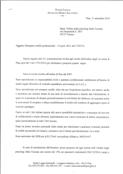
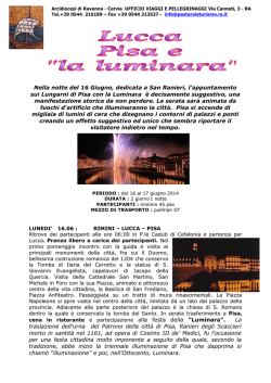
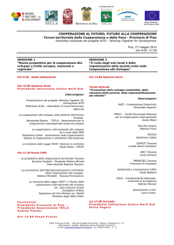
XX Congresso Nazionale AIDAA – Milano, 2009
DESIGN OF HALE-UAV SOLAR POWERED AIRCRAFT
A. Frediani1, V. Cipolla2, E. Rizzo3, M. Borghi4 and P. Rossi5
1. University of Pisa, Aerospace Engineering Department - Via G. Caruso 8, 56124 – Pisa
[email protected]
2. University of Pisa, Aerospace Engineering Department - Via G. Caruso 8, 56124 – Pisa
[email protected]
3.
4.
5.
Abstract
In the last few years, the interest towards solar powered aircraft has increased significantly for high
altitude and long endurance (HALE) missions. Unmanned aircraft (UAV), which stay aloft for many months
at 20000-30000 m of altitude, can be a less expensive alternative to present satellites, for telecommunication,
remote sensing, surveillance and control, both in civil and military field.
In a previous study, carried out at the Department of Aerospace Engineering of Pisa, a mathematical
model has been set up and four different aerodynamic solutions have been compared: a wing-tail
configuration, a flying wing, a twin boom and a biplane with vertical link-wings (see Figure 1) [1].
As a preliminary results, it has been found that the biplane solution can provide an high
aerodynamically efficient aircraft and, at the same time, a stiff structure. The lifting system of this kind of
aircraft derives from the Prandtl’s Best Wing System[4], hence the aircraft has been called PrandtlPlaneSolar (PrP-Solar).
Figure 1. An example of PrP-Solar geometry
Potentialities shown by this configuration have led up to the development of a design procedure that
consists on an iterative process with a convergence check on the weight (Figure 2); the input block contains
atmospheric and geographic data, components’ efficiencies, payload weight, flight envelope and mission
profile data. At every iteration, an inner cycle (dashed rectangle in Figure 2) verifies the energy balance over
24 hour of flight. The highlighted optimisation block aims at defining the main design parameters, which
minimize the required power. This operation is set up to have a good starting point for the iterative
procedure.
The main parameters taken into account by the optimisation tool, are the horizontal wings area (Sref),
the wingspan (bref) and the non-dimensional vertical gap between wings (Vg = ΔZLEroot/bref, see Figure 1),
The paper shows how Sref, bref and Vg influence both the required power and the available solar
power [2][3].
The aerodynamic and flight mechanic analysis has been performed using a Vortex-Lattice
Method[5], which allows us to check requirements related to longitudinal stability, trim and stall. For this
latter, the check is indirect: the algorithm which aims at finding the minimum required power solution,
exclude configurations with high values of two-dimensional CD along the wings[3].
The trim strategy is based on the internal masses displacement. In order to obtain the required margin
of stability, the centre of pressure (CP) has to be closer to the forward wing than the rearward one. Because
of the symmetry of the lifting structure, it is necessary to move internal masses in order to make the centre of
gravity (CG) coincide with the centre of pressure. The papers shows that accumulators, which are about the
45% of the PrP-Solar weight, can be successfully used to balance the aircraft.
XX Congresso Nazionale AIDAA – Milano, 2009
Input
Data
OPTIMISATION:
Initial geometry
Y
Weight Model
Structural Design
Weight of
accumulators
and solar cells
Incoming solar
power model
Weight
Convergence?
N
Output
Configuration
New geometry
N
Aerodynamics
Flight Mechanics
(VLM code)
24h Energy
Balance?
Y
Required power
New aircraft weight
N
Cruise Req.?
Y
Propulsion
system weight
Figure 2. Design procedure for solar powered aircraft
Once a stable and trimmed configuration is found, the daily energetic balance is checked taking a
24h mission into account and implementing different mission profiles[2].
In order to evaluate the range of application of a certain configuration, the concept of “Operating
Domain” has been defined: for given aircraft and mission, the related Operating Domain (OD) is the
envelope, on a plane Year’s Days - Latitude, of all the points for whom the energy balance is checked (figure
3).
Figure 3. An example of Operating Domain
When aircraft configuration and mission are given, this chart shows those combinations of day and
latitude that satisfy the energy balance. In this paper a simplified method for OD-chart tracing is shown. By
means of the present procedure, optimized aircraft at winter and summer solstices are shown and the related
OD-charts discussed.
References
[1] E.Rizzo, A.Frediani, “A model for solar powered aircraft preliminary design”, The Aeronautical Journal,
Vol. 112 No. 1128, Feb 2008
[2] P.Rossi, “Studio di fattibilità di un sistema di conversione dell'energia solare per un velivolo a
propulsione elettrica”, Master Degree Thesis in Electronic Engineering (in Italian), University of Pisa, 2008
[3] M.Borghi, “Progetto aerodinamico di un velivolo High Altitude Long Endurance (HALE) ad energia
solare”, Master Degree Thesis in Aerospace Engineering (in Italian), University of Pisa, 2008
[4] A.Frediani, “The Prandtl Wing”, Lecture Series. Innovative Configurations and Advanced Concepts for
Future Civil Aircraft, Von Karman Institute, June 06-10, 2005
[5] M.Drela, H.Youngren, “AVL 3.14 User Primer”, VLM Code User Manual, Aug 2004.
© Copyright 2026 Paperzz