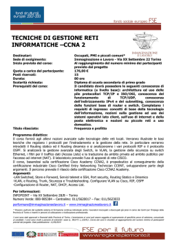
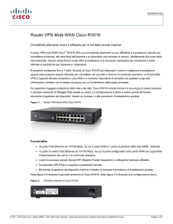
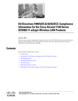
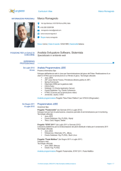
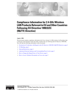
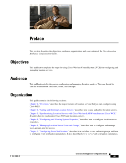
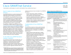
Cisco BTS 10200 Softswitch Cabling and IRDP Procedures
for Small Hardware Platform SunFire/Netra 120 Option
Feature History
Version
Modification
Release 3.5
The small hardware platform was introduced.
Release 4.1
In Release 4.1, SS7 signaling is sent via SIGTRAN to an Internet transfer
point (ITP), therefore, dedicated SS7 cables are not attached to the Cisco
BTS 10200 Softswitch. These cables have been deleted from this document.
This feature module is intended for use by service provider engineering and field personnel who are
responsible for designing, installing, configuring, and maintaining networks that use the Cisco BTS
10200 Softswitch. The procedure in this feature module describes how to cable one type of Cisco BTS
10200 Softswitch. This document is in addition to other Cisco BTS 10200 Softswitch documents that
describe how to install and operate the system. Contact your Cisco account team for the documentation
applicable to your specific system.
Scope and Purpose
This procedure is applicable to Cisco BTS 10200 Softswitch systems that are installed on the small
hardware platform, SunFire/Netra 120 option, purchased in a reference sale. In a reference sale, the
service provider purchases host machines directly from the manufacturer, based on a reference
specification provided by the Cisco account team.
Note
This hardware is different than the Continuous Computing hardware supplied by Cisco in a
direct turnkey sale (in which Cisco provides both the hardware and the software, fully integrated
and configured at the factory).
The available small hardware platform sets are:
•
AC option—A set of four Sun Fire V120 servers, two for the Element Management System (EMS)
and two for the Call Agent (CA).
•
DC option—A set of four Netra 120 servers, two for the EMS and two for the CA.
Note
Documentation for the Sun Fire V120 server and Netra 120 server is available on the Sun
Microsystems website, www.sun.com. These documents include front and rear views of the
equipment, and instructions for power cabling and general signal cabling.
Cisco BTS 10200 Softswitch Cabling and IRDP Procedures - Small Hardware Platform
OL-4881-01
1
Before You Start
The reference sale also requires two customer supplied Cisco Catalyst 2924M XL Fast Ethernet
switches. In addition, you must have an appropriate power distribution unit and an (optional) alarm panel
in your rack.
The purpose of this procedure is to explain how to:
•
Cable a new Cisco BTS 10200 Softswitch system
•
Enable Internet Control Protocol (ICMP) Router Discovery Protocol (IRDP) functionality on the
Cisco BTS 10200 Softswitch and on the Cisco routers adjacent to the Cisco BTS 10200 Softswitch
Note
This procedure is not applicable to systems with Continuous Computing hardware, nor to systems using
Sun MIcrosystems Netra 20 hardware. If you are using Continuous Computing hardware, use the Cisco
BTS 10200 Softswitch Cabling and IRDP Procedures for Medium Hardware Platform AXmp/AXi Option.
If you are useing Netra 20 hardware, use the Cisco BTS 10200 Softswitch Cabling and IRDP Procedure
for Nedium Hardware Platform Netra 20 Option.
Caution
Do not use this procedure to change the cabling of an in-service Cisco BTS 10200 Softswitch, because
that will cause interruption of service. It you need to change the cabling of in-service system, you must
first contact your network administrator or your Cisco account team for a procedure.
Before You Start
Before you start cabling the system, perform the following verifications.
1.
Verify that the hosts are already mounted in the rack according to manufacturer instructions, and
labeled appropriately. Your system should have the following hardware units:
– EMS Side A
– EMS Side B
– CA Side A
– CA Side B
– Cisco 2924M Ethernet Switch A
– Cisco 2924M Ethernet Switch B
– Power distribution unit (DC systems)
– Terminal server or alarm panel (if specified in your local documentation)
2.
Ask your supervisor or an authorized power installer to verify that appropriate power feeds are
available, as defined in the site survey documentation for your system. The electrical power for your
system must come from two separate (redundant) sources, so that a single point of failure does not
cause a complete system outage.
Cisco BTS 10200 Softswitch Cabling and IRDP Procedures - Small Hardware Platform
2
OL-4881-01
Before You Start
Warning
IMPORTANT SAFETY INSTRUCTIONS
This warning symbol means danger. You are in a situation that could cause bodily injury. Before you
work on any equipment, be aware of the hazards involved with electrical circuitry and be familiar
with standard practices for preventing accidents. Use the statement number provided at the end of
each warning to locate its translation in the translated safety warnings that accompanied this
device. Statement 1071
SAVE THESE INSTRUCTIONS
Cisco BTS 10200 Softswitch Cabling and IRDP Procedures - Small Hardware Platform
OL-4881-01
3
Network Diagram
Network Diagram
Figure 1 shows the physical interfaces and network connections.
Figure 1
Network Diagram
10.89.225.RTR
To external NEs
Alarm panel
10.89.226.RTR
To external NEs
Physical interface
EMS/BDMS Side A
EMS/BDMS Side B
OMS Hub, management (1) 10.89.225.EMSA*
NET 0
redundancy, billing (1) 10.10.122.EMSA**
NET 0
10.89.225.EMSB* OMS Hub, management (1)
10.10.122.EMSB** redundancy, billing (1)
OMS Hub, management (2) 10.89.226.EMSA*
NET 1
redundancy, billing (2) 10.10.123.EMSA**
NET 1
10.89.226.EMSB* OMS Hub, management (2)
10.10.123.EMSB** redundancy, billing (2)
CA/FS Side B
CA/FS Side A
OMS Hub, VoIP, management (1) 10.89.225.CAA*
redundancy (1) 10.10.120.CAA**
NET 0
billing (1) 10.10.122.CAA**
CA-FS communications (1) 10.10.124.CAA**
OMS Hub, VoIP, management (2) 10.89.226.CAA*
redundancy (2) 10.10.121.CAA**
NET 1
billing (2) 10.10.123.CAA**
CA-FS communications (2) 10.10.125.CAA**
Switch A
Switch B
10.89.225.CAB* OMS Hub, VoIP, management (1)
10.10.120.CAB** redundancy (1)
NET 0
10.10.122.CAB** billing (1)
10.10.124.CAB** CA-FS communications (1)
10.89.226.CAB* OMS Hub, VoIP, management (2)
10.10.121.CAB** redundancy (2)
NET 1
10.10.123.CAB** billing (2)
10.10.125.CAB** CA-FS communications (2)
87496
Data carried
Acronyms and symbols used in Figure 1:
EMS/BDMS = Element Management System/Bulk Data Management System
CA/FS = Call Agent/Feature Server
EMSA = EMS/BDMS Side A; EMSB = EMS/BDMS Side B
CAA = CA/FS Side A; CAB = CA/FS Side B
OMS Hub = communication interfaces between EMS/BDMS and CA/FS over OMS Hub
VoIP = Voice over IP signaling
* = Physical IP address
** = Logical IP address
Notes for Figure 1:
1.
The IP addresses shown in the figure are for illustration purposes only. IP address examples that
begin with 10.89 indicate externally viewable addresses, and those beginning with 10.10 indicate
internal nonroutable addresses. The actual IP address data for each Cisco BTS 10200 Softswitch is
in the Network Information Data Sheet that was supplied with your specific system.
2.
“To external NEs” refers to any of the following links in the service provider network:
•
Uplinks for external access to hosts, used for management services (via SSH, SFTP, and so
forth) and outbound billing data (via FTP)
Cisco BTS 10200 Softswitch Cabling and IRDP Procedures - Small Hardware Platform
4
OL-4881-01
Network Diagram
•
Uplinks for external communications, used for connection to external NEs and DNS services
via IRDP-enabled network
Note
3.
Caution
To support full system redundancy, it is necessary to connect the two external uplinks to separate
routers as shown in Figure 1. Furthermore, the routers must be connected to separate networks with
diverse routing paths to the applicable external NEs and services (such as OSS, DNS, media
gateways, and announcement servers).
If each of the external uplinks is not connected as described in Note #3, a single point of failure could
cause a traffic interruption.
4.
Caution
NE = Network element
SSH = Secure shell
SFTP = Secure file transfer protocol (FTP)
DNS = Domain name server
IRDP = Internet control message protocol (ICMP) router discovery protocol
To ensure redundancy of the DNS lookup function in the event of a network outage, it is strongly
recommended to have two DNS servers reachable via separate networks with diverse routing paths.
If both DNS servers become unreachable, a traffic interruption will occur.
Cisco BTS 10200 Softswitch Cabling and IRDP Procedures - Small Hardware Platform
OL-4881-01
5
Connecting Power and Grounding Cables
Connecting Power and Grounding Cables
Documentation for the Sun Fire V120 server and Netra 120 server is available on the Sun Microsystems
website, www.sun.com. These documents include front and rear views of the equipment, and instructions
for power cabling and grounding.
Warning
IMPORTANT SAFETY INSTRUCTIONS
This warning symbol means danger. You are in a situation that could cause bodily injury. Before you
work on any equipment, be aware of the hazards involved with electrical circuitry and be familiar
with standard practices for preventing accidents. Use the statement number provided at the end of
each warning to locate its translation in the translated safety warnings that accompanied this
device. Statement 1071
SAVE THESE INSTRUCTIONS
Note
Cisco strongly recommends that you use uninterruptible power for both AC and DC systems. The
uninterruptible supply should be engineered to support system operation through any possible power
interruption.
Step 1
Following the procedures and precautions in the Sun Microsystems documentation, an authorized power
installer should connect power and grounding cables to the four host machines.
Caution
Ensure redundancy of power feeds to your system, so that a single point of failure does not cause a loss
of traffic:
For AC systems (Sun Fire V120), power Side A hosts from a separate power source than Side B.
For DC systems (Netra 120), power each host from two separate (redundant) DC power feeds.
Step 2
Caution
Warning
Following the procedures and precautions in the Cisco Systems documentation, an authorized power
installer should connect power and grounding cables to the two Cisco 2924M Ethernet switches.
Ensure redundancy of power feeds to your system, so that a single point of failure does not cause a loss
of traffic:
For AC systems, power Ethernet Switch A from a separate power source than Ethernet Switch B.
For DC systems, power each Ethernet Switch from two separate (redundant) DC power feeds.
This equipment must be grounded. Never defeat the ground conductor or operate the equipment in
the absence of a suitably installed ground conductor. Contact the appropriate electrical inspection
authority or an electrician if you are uncertain that suitable grounding is available. Statement 1024
Cisco BTS 10200 Softswitch Cabling and IRDP Procedures - Small Hardware Platform
6
OL-4881-01
Labeling the Ethernet Cables
Labeling the Ethernet Cables
Two Ethernet cables are supplied with each host machine. Make sure that all of the Ethernet cables are
correctly labeled before you begin. It is suggested that you label the cables according to the procedure
in Appendix A: Cable Labeling, page 14 and Table 1 in Appendix B: Cable Lists, page 15.
Connecting Ethernet Cables to EMS and CA Units
Follow these steps to connect the Ethernet cables from the host machines (EMS and CA) to the Ethernet
switches.
Step 1
Obtain the 4 Ethernet cables needed for connections between EMS Sides A and B and the two Cisco
2924M Ethernet Switches A and B. These cables are listed in Table 1 in Appendix B: Cable Lists,
page 15.
Step 2
Connect these 4 Ethernet cables between the ports on the rear panel of the EMS units and the ports on
the front of the Ethernet switches as specified in Table 1.
Step 3
Obtain the 4 Ethernet cables needed for connections between CA Sides A and B and the two Cisco
2924M Ethernet Switches A and B. These cables are listed in Table 1.
Step 4
Connect these 4 Ethernet cables between the ports on the rear panel of the CA units and the ports on the
front of the Ethernet switches as specified in Table 1.
Step 5
After installing the Ethernet cables, record the necessary information on a copy of Table 1 or similar
document according to local procedures.
Connect External Network Uplink Cables to Ethernet Switches
External network uplink cables are customer supplied. Follow these steps to connect uplink cables to the
Ethernet switches.
Note
If your local network documentation calls for gigabit Ethernet, contact Cisco TAC for assistance.
Step 1
If your local network documentation calls for 100 Mb Ethernet, connect the applicable network uplink
cables to the Ethernet Switches as listed in Table 1.
Step 2
After installing the uplink cables, record the necessary information on a copy of Table 1 or similar
document according to local procedures.
Cisco BTS 10200 Softswitch Cabling and IRDP Procedures - Small Hardware Platform
OL-4881-01
7
Connecting Serial Cables to Alarm Panel or Terminal Server
Connecting Serial Cables to Alarm Panel or Terminal Server
Remote management of the Cisco BTS 10200 requires serial cables connected from the four host
machines and two Ethernet Switches to a terminal server. If specified in your local work order, connect
these serial cables using the steps in this section. Note that some commercially available alarm panels
have built-in terminal server capability.
Caution
The serial cables used in this procedure are not reversible. Be sure to label and connect the ends as
specified.
Note
The Sun Fire V120/Netra 120 host machines allow alarm messages to be transmitted from the lights-out
management port (A LOM port) on the rear panel. However, the Cisco BTS 10200 software does not
currently transmit machine alarms through this port. Instead, machine alarms are sent via alarm reports,
as described in the Cisco BTS 10200 Softswitch Error Messages and Alarms Reference Guide.
Tip
See the Sun Microsystems documentation for instructions on using the LOM features.
Procedure for Use with Third-Party Terminal Server or Alarm Panel
This procedure is applicable if your terminal server or alarm panel is not the Continuous Computing
Intelligent Alarm Panel. If you are using a Continuous Computing Intelligent Alarm Panel, see the
“Procedure for Use with Continuous Computing Intelligent Alarm Panel” section on page 9.
Step 1
Obtain the four serial cables that connect the lights-out management port (A LOM port) of the Sun Fire
V120/Netra 120 host machines and an alarm panel or terminal server. If these cables have not been
provided, see Step 2.
Step 2
If necessary, make one serial cable for each SunFire V120/Netra 120 host machine. Follow the
procedures in the Sun Microsystems documentation and the terminal server documentation. It is
suggested that you label the cables according to the procedure in Appendix A: Cable Labeling, page 14
and Table 1 in Appendix B: Cable Lists, page 15.
Step 3
Connect a serial cable between the A LOM port of each Sun Fire V120/Netra 120 host machine and the
alarm panel or terminal server. Follow the procedures in the Sun Microsystems documentation and the
terminal server documentation.
Step 4
Obtain the two serial cables that connect the CONSOLE port of each Cisco 2924M Ethernet Switch to
the alarm panel or terminal server. If these cables have not been provided, see Step 5.
Step 5
If necessary, make one serial cable for each Cisco 2924M Ethernet Switch. Follow the procedures in the
Ethernet switch documentation and the terminal server documentation. It is suggested that you label the
cables according to the procedure in Appendix A: Cable Labeling, page 14 and Table 1 in Appendix B:
Cable Lists, page 15.
Step 6
Connect a serial cable between the CONSOLE port of each Cisco 2924M Ethernet Switch and the alarm
panel or terminal server. Follow the procedures in the Ethernet switch documentation and the terminal
server documentation.
Cisco BTS 10200 Softswitch Cabling and IRDP Procedures - Small Hardware Platform
8
OL-4881-01
Connecting Serial Cables to Alarm Panel or Terminal Server
Record the necessary information on a copy of Table 1 or similar document according to local
procedures
Step 7
Procedure for Use with Continuous Computing Intelligent Alarm Panel
This procedure is applicable if your terminal server or alarm panel is the Continuous Computing
Intelligent Alarm Panel. If you are using a different terminal server or alarm panel, see the “Procedure
for Use with Third-Party Terminal Server or Alarm Panel” section on page 8.
The rear view of the Continuous Computing Intelligent Alarm Panel is shown in Figure 2. (The drawing
is not to scale.)
Rear View of Continuous Computing Intelligent Alarm Panel
CCPUNet HUB A
LINE
1
2
3
4
5
6
7
1
2
3
4
5
6
7
CCPUNet HUB B
SER 1 SER 3 SER 5 SER 7 SER 9 SER 11 CONS
eth1
I/O CABLE A
SER 2 SER 4 SER 6 SER 8 SER 10 SER 12 COM1
eth0
I/O CABLE B
-48V A
-48V B
AC IN
8
8
REM
100-240 V50-60 HZ 40W
69752
Figure 2
Step 1
Obtain the four serial cables that connect the lights-out management port (A LOM port) of the Sun Fire
V120/Netra 120 host machines and the Alarm Panel. These cables are listed in Table 2 in Appendix B:
Cable Lists, page 15.
Step 2
Connect a serial cable between the A LOM port of each Sun Fire V120/Netra 120 host machine and the
Alarm Panel serial ports as specified in Table 2.
Note
The four LOM serial cables are specially designed for the connecting the LOM ports on the
SunFire V120/Netra 120 to the SER ports on the Alarm Panel. Be sure to use the correct cables
and connect them as labeled (LOM end and SER end must be connected as labeled).
Step 3
Obtain the two serial cables that connect the CONSOLE port of each Cisco 2924M Ethernet Switch to
the Alarm Panel. These cables are listed in Table 2 in Appendix B: Cable Lists, page 15.
Step 4
Connect a serial cable between the CONSOLE port of each Cisco 2924M Ethernet Switch and the Alarm
Panel serial ports as specified in Table 2.
Note
The two CONSOLE serial cables are specially designed for the connecting the CONSOLE ports
on the Cisco 2924M Ethernet Switches to the SER ports on the Alarm Panel. Be sure to use the
correct cables and connect them as labeled (SWITCH end and SER end must be connected as
labeled).
Note that in some earlier installations, these cables were labeled “SWITCH” and “net CCN”,
where net CCN is treated the same as SER.
Cisco BTS 10200 Softswitch Cabling and IRDP Procedures - Small Hardware Platform
OL-4881-01
9
Connecting Serial Cables to Alarm Panel or Terminal Server
Step 5
Record the necessary information on a copy of Table 2 or similar document according to local
procedures.
Cisco BTS 10200 Softswitch Cabling and IRDP Procedures - Small Hardware Platform
10
OL-4881-01
Enable IRDP
Enable IRDP
This section explains how to enable IRDP functionality on the Cisco BTS 10200 Softswitch and on the
network router.
Note
IRDP = Internet control message protocol (ICMP) router discovery protocol.
Enable IRDP on the Cisco BTS 10200 Softswitch
Follow these steps to enable IRDP on the Cisco BTS 10200 Softswitch.
Note
You should already have the Cisco BTS 10200 Softswitch application software installed on the
system.
Step 1
Log in to EMS Side A as root user.
Step 2
Remove the defaultrouter file from /etc.
Step 3
There should be three default routes in the routing table. Remove all three of these with the following
command:
route delete net default <gateway address>
Step 4
Execute the following command:
/usr/sbin/in.rdisc -s -f
Step 5
Note
Step 6
Edit S69inet and search and replace for rdisc -s with rdisc -s -f.
This will ensure that reboot will enable the irdp daemon.
Put the following lines into the S68inet file:
if [ -f /usr/sbin/in.routed ];
then
\mv -f /usr/sbin/in.routed /usr/sbin/in.routed.org
Step 7
Repeat Step 1 through Step 6 for EMS Side B.
Step 8
Repeat Step 1 through Step 6 for CA Side A.
Step 9
Repeat Step 1 through Step 6 for CA Side B.
Cisco BTS 10200 Softswitch Cabling and IRDP Procedures - Small Hardware Platform
OL-4881-01
11
Enable IRDP
Enable IRDP on Adjacent Cisco Routers
If you are enabling IRDP on Cisco routers adjacent to the Cisco BTS 10200 Softswitch, follow these
steps. If you have any questions about setup of these routers, contact your system administrator. If you
need additional assistance, contact Cisco TAC.
Step 1
Verify that you have the Network Information Data Sheet (NIDS) applicable to this
Cisco BTS 10200 Softswitch. If necessary, contact your network administrator to verify that you have
the correct NIDS.
Step 2
On default gateway interfaces for Network 1 and Network 2 (as defined in the NIDS) enable IRDP using
the following commands:
config t
interface <Fast Ethernet interface number (see NIDS)>
ip irdp
ip irdp maxadvertinterval 4
ip irdp minadvertinterval 3
ip irdp holdtime 10
Step 3
Validate the configuration by performing the following command on both CA/FS hosts and both EMS
hosts:
login as root
#netstat -rn
Step 4
View the display and verify that each default route was populated dynamically by IRDP.
Verify IRDP Functions
Follow these steps to verify that IRDP is functioning properly on the network:
CA Side A
Perform Step 1 through Step 11 on CA Side A.
Step 1
Login to CA Side A as root.
Step 2
Display the IRDP daemon status by entering the following command:
ps -ef|grep in.rdisc
Step 3
View the display and verify that each default route was populated dynamically by IRDP. The display
should include the following information: /usr/sbin/in.rdisc -s -f. (This indicates that IRDP is running
properly.)
Cisco BTS 10200 Softswitch Cabling and IRDP Procedures - Small Hardware Platform
12
OL-4881-01
Verify Interfaces
Step 4
Display the routing table by entering the following command:
netstat -rn
Step 5
Verify that the routing table shows two default routes, one on interface NET 0 and one on NET 1.
Step 6
Unplug the interface NET 0 link at the back of CA Side A.
Step 7
Display the routing table by entering the following command:
netstat -rn
Step 8
Verify that the route for interface NET 0 does not appear in the routing table.
Note
When a link is unplugged or plugged back in, it may take 5 to 10 seconds for the IRDP function
to automatically update.
Step 9
Plug the interface NET 0 link back in to CA Side A.
Step 10
Display the routing table (netstat -rn) and verify that the route for interface NET 0 appears in the routing
table again.
Step 11
Repeat Step 6 through Step 10 for the interface NET 1 link.
CA Side B
Repeat Step 1 through Step 11 for CA Side B.
Verify Interfaces
Follow these steps to verify that all interfaces are configured on all computing elements:
Step 1
If the Cisco BTS 10200 Softswitch application software has already been installed on the system, go to
Step 2. If the application has not been installed, go to Step 4.
Step 2
(If the Cisco BTS 10200 Softswitch application software has already been installed on the system)
check the interface configurations using the following command on each of the four platforms (two EMS
units and two CA/FS units):
Enter: checkCFG
Step 3
The system should display the message Validating..... If no errors are found during validation, the system
will display the message No errors found. Verify that the No errors found message is displayed.
Note
Step 4
If the system does display an error, contact Cisco TAC for assistance.
If the Cisco BTS 10200 Softswitch application software has not been installed on the system, install the
application using the Application Installation procedure provided by Cisco. That procedure contains the
appropriate commands to check the configurations (checkCFG).
Cisco BTS 10200 Softswitch Cabling and IRDP Procedures - Small Hardware Platform
OL-4881-01
13
Appendix A: Cable Labeling
Appendix A: Cable Labeling
Cables are labeled at both ends with the cable numbers listed in Table 1 and Table 2, as applicable.
Follow these steps to create and attach the labels.
Note
The steps in this section are not necessary for any cables that were provided with your system and have
already been labeled.
Step 1
Make each label by copying the applicable number from Table 1 (or Table 2) onto the label. Be sure to
duplicate the number several times onto the label, as shown in Figure 3, to make it easier to read. (If
desired, make the labels for all cables in one print run.)
Step 2
On a work bench or assembly table, position a cable so that one connector is on your left and the cable
goes off to the right. (See Figure 3.)
Step 3
Attach the appropriate label to the cable as shown in Figure 3.
Step 4
Turn the cable around so that the other connector is on your left with the cable going off to the right.
Step 5
Repeat Step 2 and Step 3 for this side of the cable. The completed cable should look like the example
shown in Figure 4.
Step 6
Repeat these steps for all cables in the rack, using the numbers from the cable lists (Table 1 and Table 2
as applicable).
Labeling Specification
#16
#16
#16
#16
#16
Surface of connector that is flush
with rear panel when installed.
Cable
#16
#16
#16
Label (example)
to match cable list
1 inch
Completed Cable Example
#16
#16
#16
#16
#16
#16
Figure 4
54358
Connector
Multiple rows on label, sufficient
to ensure that label can be read
without need to rotate or twist cable.
54357
Figure 3
Cisco BTS 10200 Softswitch Cabling and IRDP Procedures - Small Hardware Platform
14
OL-4881-01
Appendix B: Cable Lists
Appendix B: Cable Lists
Table 1 lists the ports and cables used for signaling and system management. Make a copy of this table
for your records. It is recommended that you sign or check each box in the Verified column as you
connect the cables. Store this completed table in the documentation package for this unit.
Note
This table does not include the power, grounding, or alarm panel cabling. For those cables, follow the
procedures and precautions in the manufacturers’ documentation.
Table 1
List of Signaling and System Management Cables (See Procedure for Details)
From (Unit, Port)
To (Unit, Port)
Suggested
Cable No.
CA-A NET 0
SWITCH-A 1
#701
CA-A NET 1
SWITCH-B 1
#702
CA-B NET 0
SWITCH-A 2
#703
CA-B NET 1
SWITCH-B 2
#704
EMS-A NET 0
SWITCH-A 3
#705
EMS-A NET 1
SWITCH-B 3
#706
EMS-B NET 0
SWITCH-A 4
#707
EMS-B NET 1
SWITCH-B 4
Verified
#708
1
SWITCH-A 10
(see footnote 1)
Uplink to router for external communications
(Network 1)
SWITCH-B 10
(see footnote 1)
Uplink to router for external communications1
(Network 2)
CA-A Serial A LOM
Terminal server serial port # ____ (if used) 2
EMS-A Serial A LOM
Terminal server serial port # ____ (if used) 2
SWITCH-A CONSOLE
Terminal server serial port # ____ (if used) 2
SWITCH-B CONSOLE
Terminal server serial port # ____ (if used) 2
CA-B Serial A LOM
Terminal server serial port # ____ (if used) 2
EMS-B Serial A LOM
Terminal server serial port # ____ (if used) 2
CA-A B SERIAL
if used
CA-B B SERIAL
if used
EMS-A B SERIAL
if used
EMS-B B SERIAL
if used
1. The ports shown are applicable to 100 Mb Ethernet uplinks. Cable No. for uplink connections are customer-defined. See the
procedure for more information. If you need to connect gigabit Ethernet instead of 100Mb Ethernet, contact Cisco TAC for
assistance.
2. If you are using a Continuous Computing Intelligent Alarm Panel, use Table 2 instead of these six rows. See the procedure
for details.
Cisco BTS 10200 Softswitch Cabling and IRDP Procedures - Small Hardware Platform
OL-4881-01
15
Appendix B: Cable Lists
Table 2 lists the ports and cables used for serial cables that connect from the Continuous Computing
Intelligent Alarm Panel to the SunFire V120/Netra 120 A LOM ports and the 2924M Ethernet Switch
CONSOLE ports. Make a copy of this table for your records. It is recommended that you sign or check
each box in the Verified column as you connect the cables. Store this completed table in the
documentation package for this unit.
Note
If your terminal server or alarm panel is not from Continuous Computing Intelligent Alarm Panel, do not
use Table 2. Go back to Table 1.
Note
The four LOM serial cables are specially designed for the connecting the LOM ports on the
SunFire V120/Netra 120 to the SER ports on the Alarm Panel. Be sure to use the correct cables
and connect them as labeled (LOM end and SER end must be connected as labeled).
Note
The two CONSOLE serial cables are specially designed for the connecting the CONSOLE ports
on the Cisco 2924M Ethernet Switches to the SER ports on the Alarm Panel. Be sure to use the
correct cables and connect them as labeled (SWITCH end and SER end must be connected as
labeled).
Note that in some earlier installations, these cables were labeled “SWITCH” and “net CCN”,
where net CCN is treated the same as SER.
Table 2
List of Serial Cables for Use with Continuous Computing Intelligent Alarm Panel
(See Procedure for Details)
From (Unit, Port)
To (Unit, Port)
Suggested
Cable No.
CA-A Serial A LOM
ALARM SER 1
801
EMS-A Serial A LOM
ALARM SER 2
802
SWITCH-A CONSOLE
ALARM SER 3
803
SWITCH-B CONSOLE
ALARM SER 4
804
CA-B Serial A LOM
ALARM SER 5
805
EMS-B Serial A LOM
ALARM SER 6
806
Verified
Cisco BTS 10200 Softswitch Cabling and IRDP Procedures - Small Hardware Platform
16
OL-4881-01
Appendix C: Translated Safety Warnings
Appendix C: Translated Safety Warnings
Statement 1071—Warning Definition
Warning
IMPORTANT SAFETY INSTRUCTIONS
This warning symbol means danger. You are in a situation that could cause bodily injury. Before you
work on any equipment, be aware of the hazards involved with electrical circuitry and be familiar
with standard practices for preventing accidents. Use the statement number provided at the end of
each warning to locate its translation in the translated safety warnings that accompanied this
device. Statement 1071
SAVE THESE INSTRUCTIONS
Waarschuwing
BELANGRIJKE VEILIGHEIDSINSTRUCTIES
Dit waarschuwingssymbool betekent gevaar. U verkeert in een situatie die lichamelijk letsel kan
veroorzaken. Voordat u aan enige apparatuur gaat werken, dient u zich bewust te zijn van de bij
elektrische schakelingen betrokken risico's en dient u op de hoogte te zijn van de standaard
praktijken om ongelukken te voorkomen. Gebruik het nummer van de verklaring onderaan de
waarschuwing als u een vertaling van de waarschuwing die bij het apparaat wordt geleverd, wilt
raadplegen.
BEWAAR DEZE INSTRUCTIES
Varoitus
TÄRKEITÄ TURVALLISUUSOHJEITA
Tämä varoitusmerkki merkitsee vaaraa. Tilanne voi aiheuttaa ruumiillisia vammoja. Ennen kuin
käsittelet laitteistoa, huomioi sähköpiirien käsittelemiseen liittyvät riskit ja tutustu
onnettomuuksien yleisiin ehkäisytapoihin. Turvallisuusvaroitusten käännökset löytyvät laitteen
mukana toimitettujen käännettyjen turvallisuusvaroitusten joukosta varoitusten lopussa näkyvien
lausuntonumeroiden avulla.
SÄILYTÄ NÄMÄ OHJEET
Attention
IMPORTANTES INFORMATIONS DE SÉCURITÉ
Ce symbole d'avertissement indique un danger. Vous vous trouvez dans une situation pouvant
entraîner des blessures ou des dommages corporels. Avant de travailler sur un équipement, soyez
conscient des dangers liés aux circuits électriques et familiarisez-vous avec les procédures
couramment utilisées pour éviter les accidents. Pour prendre connaissance des traductions des
avertissements figurant dans les consignes de sécurité traduites qui accompagnent cet appareil,
référez-vous au numéro de l'instruction situé à la fin de chaque avertissement.
CONSERVEZ CES INFORMATIONS
Cisco BTS 10200 Softswitch Cabling and IRDP Procedures - Small Hardware Platform
OL-4881-01
17
Appendix C: Translated Safety Warnings
Warnung
WICHTIGE SICHERHEITSHINWEISE
Dieses Warnsymbol bedeutet Gefahr. Sie befinden sich in einer Situation, die zu Verletzungen führen
kann. Machen Sie sich vor der Arbeit mit Geräten mit den Gefahren elektrischer Schaltungen und
den üblichen Verfahren zur Vorbeugung vor Unfällen vertraut. Suchen Sie mit der am Ende jeder
Warnung angegebenen Anweisungsnummer nach der jeweiligen Übersetzung in den übersetzten
Sicherheitshinweisen, die zusammen mit diesem Gerät ausgeliefert wurden.
BEWAHREN SIE DIESE HINWEISE GUT AUF.
Avvertenza
IMPORTANTI ISTRUZIONI SULLA SICUREZZA
Questo simbolo di avvertenza indica un pericolo. La situazione potrebbe causare infortuni alle
persone. Prima di intervenire su qualsiasi apparecchiatura, occorre essere al corrente dei pericoli
relativi ai circuiti elettrici e conoscere le procedure standard per la prevenzione di incidenti.
Utilizzare il numero di istruzione presente alla fine di ciascuna avvertenza per individuare le
traduzioni delle avvertenze riportate in questo documento.
CONSERVARE QUESTE ISTRUZIONI
Advarsel
VIKTIGE SIKKERHETSINSTRUKSJONER
Dette advarselssymbolet betyr fare. Du er i en situasjon som kan føre til skade på person. Før du
begynner å arbeide med noe av utstyret, må du være oppmerksom på farene forbundet med
elektriske kretser, og kjenne til standardprosedyrer for å forhindre ulykker. Bruk nummeret i slutten
av hver advarsel for å finne oversettelsen i de oversatte sikkerhetsadvarslene som fulgte med denne
enheten.
TA VARE PÅ DISSE INSTRUKSJONENE
Aviso
INSTRUÇÕES IMPORTANTES DE SEGURANÇA
Este símbolo de aviso significa perigo. Você está em uma situação que poderá ser causadora de
lesões corporais. Antes de iniciar a utilização de qualquer equipamento, tenha conhecimento dos
perigos envolvidos no manuseio de circuitos elétricos e familiarize-se com as práticas habituais de
prevenção de acidentes. Utilize o número da instrução fornecido ao final de cada aviso para
localizar sua tradução nos avisos de segurança traduzidos que acompanham este dispositivo.
GUARDE ESTAS INSTRUÇÕES
¡Advertencia!
INSTRUCCIONES IMPORTANTES DE SEGURIDAD
Este símbolo de aviso indica peligro. Existe riesgo para su integridad física. Antes de manipular
cualquier equipo, considere los riesgos de la corriente eléctrica y familiarícese con los
procedimientos estándar de prevención de accidentes. Al final de cada advertencia encontrará el
número que le ayudará a encontrar el texto traducido en el apartado de traducciones que acompaña
a este dispositivo.
GUARDE ESTAS INSTRUCCIONES
Cisco BTS 10200 Softswitch Cabling and IRDP Procedures - Small Hardware Platform
18
OL-4881-01
Appendix C: Translated Safety Warnings
Varning!
VIKTIGA SÄKERHETSANVISNINGAR
Denna varningssignal signalerar fara. Du befinner dig i en situation som kan leda till personskada.
Innan du utför arbete på någon utrustning måste du vara medveten om farorna med elkretsar och
känna till vanliga förfaranden för att förebygga olyckor. Använd det nummer som finns i slutet av
varje varning för att hitta dess översättning i de översatta säkerhetsvarningar som medföljer denna
anordning.
SPARA DESSA ANVISNINGAR
Cisco BTS 10200 Softswitch Cabling and IRDP Procedures - Small Hardware Platform
OL-4881-01
19
Appendix C: Translated Safety Warnings
Aviso
INSTRUÇÕES IMPORTANTES DE SEGURANÇA
Este símbolo de aviso significa perigo. Você se encontra em uma situação em que há risco de lesões
corporais. Antes de trabalhar com qualquer equipamento, esteja ciente dos riscos que envolvem os
circuitos elétricos e familiarize-se com as práticas padrão de prevenção de acidentes. Use o
número da declaração fornecido ao final de cada aviso para localizar sua tradução nos avisos de
segurança traduzidos que acompanham o dispositivo.
GUARDE ESTAS INSTRUÇÕES
Advarsel
VIGTIGE SIKKERHEDSANVISNINGER
Dette advarselssymbol betyder fare. Du befinder dig i en situation med risiko for
legemesbeskadigelse. Før du begynder arbejde på udstyr, skal du være opmærksom på de
involverede risici, der er ved elektriske kredsløb, og du skal sætte dig ind i standardprocedurer til
undgåelse af ulykker. Brug erklæringsnummeret efter hver advarsel for at finde oversættelsen i de
oversatte advarsler, der fulgte med denne enhed.
GEM DISSE ANVISNINGER
Cisco BTS 10200 Softswitch Cabling and IRDP Procedures - Small Hardware Platform
20
OL-4881-01
Appendix C: Translated Safety Warnings
Cisco BTS 10200 Softswitch Cabling and IRDP Procedures - Small Hardware Platform
OL-4881-01
21
Appendix C: Translated Safety Warnings
Statement 1024—Ground Conductor
Warning
This equipment must be grounded. Never defeat the ground conductor or operate the equipment in
the absence of a suitably installed ground conductor. Contact the appropriate electrical inspection
authority or an electrician if you are uncertain that suitable grounding is available. Statement 1024
Waarschuwing
Deze apparatuur dient geaard te zijn. De aardingsleiding mag nooit buiten werking worden gesteld
en de apparatuur mag nooit bediend worden zonder dat er een op de juiste wijze geïnstalleerde
aardingsleiding aanwezig is. Neem contact op met de bevoegde instantie voor elektrische
inspecties of met een elektricien als u er niet zeker van bent dat er voor passende aarding
gezorgd is.
Varoitus
Laitteiden on oltava maadoitettuja. Älä koskaan ohita maajohdinta tai käytä laitteita ilman oikein
asennettua maajohdinta. Ota yhteys sähkötarkastusviranomaiseen tai sähköasentajaan, jos olet
epävarma maadoituksen sopivuudesta.
Attention
Cet équipement doit être mis à la masse. Ne jamais rendre inopérant le conducteur de masse ni
utiliser l'équipement sans un conducteur de masse adéquatement installé. En cas de doute sur la
mise à la masse appropriée disponible, s'adresser à l'organisme responsable de la sécurité
électrique ou à un électricien.
Cisco BTS 10200 Softswitch Cabling and IRDP Procedures - Small Hardware Platform
22
OL-4881-01
Appendix C: Translated Safety Warnings
Warnung
Dieses Gerät muss geerdet sein. Auf keinen Fall den Erdungsleiter unwirksam machen oder das
Gerät ohne einen sachgerecht installierten Erdungsleiter verwenden. Wenn Sie sich nicht sicher
sind, ob eine sachgerechte Erdung vorhanden ist, wenden Sie sich an die zuständige
Inspektionsbehörde oder einen Elektriker.
Avvertenza
Questa apparecchiatura deve essere dotata di messa a terra. Non escludere mai il conduttore di
protezione né usare l'apparecchiatura in assenza di un conduttore di protezione installato in modo
corretto. Se non si è certi della disponibilità di un adeguato collegamento di messa a terra,
richiedere un controllo elettrico presso le autorità competenti o rivolgersi a un elettricista.
Advarsel
Dette utstyret må jordes. Omgå aldri jordingslederen og bruk aldri utstyret uten riktig montert
jordingsleder. Ta kontakt med fagfolk innen elektrisk inspeksjon eller med en elektriker hvis du er
usikker på om det finnes velegnet jordning.
Aviso
Este equipamento deve ser aterrado. Nunca anule o fio terra nem opere o equipamento sem um
aterramento adequadamente instalado. Em caso de dúvida com relação ao sistema de aterramento
disponível, entre em contato com os serviços locais de inspeção elétrica ou um eletricista
qualificado.
¡Advertencia!
Este equipo debe estar conectado a tierra. No inhabilite el conductor de tierra ni haga funcionar el
equipo si no hay un conductor de tierra instalado correctamente. Póngase en contacto con la
autoridad correspondiente de inspección eléctrica o con un electricista si no está seguro de que
haya una conexión a tierra adecuada.
Varning!
Denna utrustning måste jordas. Koppla aldrig från jordledningen och använd aldrig utrustningen
utan en på lämpligt sätt installerad jordledning. Om det föreligger osäkerhet huruvida lämplig
jordning finns skall elektrisk besiktningsauktoritet eller elektriker kontaktas.
Cisco BTS 10200 Softswitch Cabling and IRDP Procedures - Small Hardware Platform
OL-4881-01
23
Obtaining Documentation
Obtaining Documentation
Cisco provides several ways to obtain documentation, technical assistance, and other technical
resources. These sections explain how to obtain technical information from Cisco Systems.
Cisco.com
You can access the most current Cisco documentation on the World Wide Web at this URL:
http://www.cisco.com/univercd/home/home.htm
You can access the Cisco website at this URL:
http://www.cisco.com
International Cisco web sites can be accessed from this URL:
http://www.cisco.com/public/countries_languages.shtml
Documentation CD-ROM
Cisco documentation and additional literature are available in a Cisco Documentation CD-ROM
package, which may have shipped with your product. The Documentation CD-ROM is updated monthly
and may be more current than printed documentation. The CD-ROM package is available as a single unit
or through an annual subscription.
Registered Cisco.com users can order the Documentation CD-ROM (product number
DOC-CONDOCCD=) through the online Subscription Store:
http://www.cisco.com/go/subscription
Ordering Documentation
You can find instructions for ordering documentation at this URL:
http://www.cisco.com/univercd/cc/td/doc/es_inpck/pdi.htm
You can order Cisco documentation in these ways:
•
Registered Cisco.com users (Cisco direct customers) can order Cisco product documentation from
the Networking Products MarketPlace:
http://www.cisco.com/en/US/partner/ordering/index.shtml
•
Registered Cisco.com users can order the Documentation CD-ROM (Customer Order Number
DOC-CONDOCCD=) through the online Subscription Store:
http://www.cisco.com/go/subscription
•
Nonregistered Cisco.com users can order documentation through a local account representative by
calling Cisco Systems Corporate Headquarters (California, U.S.A.) at 408 526-7208 or, elsewhere
in North America, by calling 800 553-NETS (6387).
Cisco BTS 10200 Softswitch Cabling and IRDP Procedures - Small Hardware Platform
24
OL-4881-01
Obtaining Technical Assistance
Documentation Feedback
You can submit comments electronically on Cisco.com. On the Cisco Documentation home page, click
Feedback at the top of the page.
You can e-mail your comments to [email protected].
You can submit your comments by mail by using the response card behind the front cover of your
document or by writing to the following address:
Cisco Systems
Attn: Customer Document Ordering
170 West Tasman Drive
San Jose, CA 95134-9883
We appreciate your comments.
Obtaining Technical Assistance
Cisco provides Cisco.com, which includes the Cisco Technical Assistance Center (TAC) Website, as a
starting point for all technical assistance. Customers and partners can obtain online documentation,
troubleshooting tips, and sample configurations from the Cisco TAC website. Cisco.com registered users
have complete access to the technical support resources on the Cisco TAC website, including TAC tools
and utilities.
Cisco.com
Cisco.com offers a suite of interactive, networked services that let you access Cisco information,
networking solutions, services, programs, and resources at any time, from anywhere in the world.
Cisco.com provides a broad range of features and services to help you with these tasks:
•
Streamline business processes and improve productivity
•
Resolve technical issues with online support
•
Download and test software packages
•
Order Cisco learning materials and merchandise
•
Register for online skill assessment, training, and certification programs
To obtain customized information and service, you can self-register on Cisco.com at this URL:
http://www.cisco.com
Technical Assistance Center
The Cisco TAC is available to all customers who need technical assistance with a Cisco product,
technology, or solution. Two levels of support are available: the Cisco TAC website and the Cisco TAC
Escalation Center. The avenue of support that you choose depends on the priority of the problem and the
conditions stated in service contracts, when applicable.
We categorize Cisco TAC inquiries according to urgency:
•
Priority level 4 (P4)—You need information or assistance concerning Cisco product capabilities,
product installation, or basic product configuration.
Cisco BTS 10200 Softswitch Cabling and IRDP Procedures - Small Hardware Platform
OL-4881-01
25
Obtaining Additional Publications and Information
•
Priority level 3 (P3)—Your network performance is degraded. Network functionality is noticeably
impaired, but most business operations continue.
•
Priority level 2 (P2)—Your production network is severely degraded, affecting significant aspects
of business operations. No workaround is available.
•
Priority level 1 (P1)—Your production network is down, and a critical impact to business operations
will occur if service is not restored quickly. No workaround is available.
Cisco TAC Website
You can use the Cisco TAC website to resolve P3 and P4 issues yourself, saving both cost and time. The
site provides around-the-clock access to online tools, knowledge bases, and software. To access the
Cisco TAC website, go to this URL:
http://www.cisco.com/tac
All customers, partners, and resellers who have a valid Cisco service contract have complete access to
the technical support resources on the Cisco TAC website. Some services on the Cisco TAC website
require a Cisco.com login ID and password. If you have a valid service contract but do not have a login
ID or password, go to this URL to register:
http://tools.cisco.com/RPF/register/register.do
If you are a Cisco.com registered user, and you cannot resolve your technical issues by using the Cisco
TAC website, you can open a case online at this URL:
http://www.cisco.com/en/US/support/index.html
If you have Internet access, we recommend that you open P3 and P4 cases through the Cisco TAC
website so that you can describe the situation in your own words and attach any necessary files.
Cisco TAC Escalation Center
The Cisco TAC Escalation Center addresses priority level 1 or priority level 2 issues. These
classifications are assigned when severe network degradation significantly impacts business operations.
When you contact the TAC Escalation Center with a P1 or P2 problem, a Cisco TAC engineer
automatically opens a case.
To obtain a directory of toll-free Cisco TAC telephone numbers for your country, go to this URL:
http://www.cisco.com/warp/public/687/Directory/DirTAC.shtml
Before calling, please check with your network operations center to determine the level of Cisco support
services to which your company is entitled: for example, SMARTnet, SMARTnet Onsite, or Network
Supported Accounts (NSA). When you call the center, please have available your service agreement
number and your product serial number.
Obtaining Additional Publications and Information
Information about Cisco products, technologies, and network solutions is available from various online
and printed sources.
•
The Cisco Product Catalog describes the networking products offered by Cisco Systems as well as
ordering and customer support services. Access the Cisco Product Catalog at this URL:
http://www.cisco.com/en/US/products/products_catalog_links_launch.html
Cisco BTS 10200 Softswitch Cabling and IRDP Procedures - Small Hardware Platform
26
OL-4881-01
Obtaining Additional Publications and Information
•
Cisco Press publishes a wide range of networking publications. Cisco suggests these titles for new
and experienced users: Internetworking Terms and Acronyms Dictionary, Internetworking
Technology Handbook, Internetworking Troubleshooting Guide, and the Internetworking Design
Guide. For current Cisco Press titles and other information, go to Cisco Press online at this URL:
http://www.ciscopress.com
•
Packet magazine is the Cisco monthly periodical that provides industry professionals with the latest
information about the field of networking. You can access Packet magazine at this URL:
http://www.cisco.com/en/US/about/ac123/ac114/about_cisco_packet_magazine.html
•
iQ Magazine is the Cisco monthly periodical that provides business leaders and decision makers
with the latest information about the networking industry. You can access iQ Magazine at this URL:
http://business.cisco.com/prod/tree.taf%3fasset_id=44699&public_view=true&kbns=1.html
•
Internet Protocol Journal is a quarterly journal published by Cisco Systems for engineering
professionals involved in the design, development, and operation of public and private internets and
intranets. You can access the Internet Protocol Journal at this URL:
http://www.cisco.com/en/US/about/ac123/ac147/about_cisco_the_internet_protocol_journal.html
•
Training—Cisco offers world-class networking training, with current offerings in network training
listed at this URL:
http://www.cisco.com/en/US/learning/le31/learning_recommended_training_list.html
Cisco BTS 10200 Softswitch Cabling and IRDP Procedures - Small Hardware Platform
OL-4881-01
27
Obtaining Additional Publications and Information
THE SPECIFICATIONS AND INFORMATION REGARDING THE PRODUCTS IN THIS MANUAL ARE SUBJECT TO CHANGE WITHOUT
NOTICE. ALL STATEMENTS, INFORMATION, AND RECOMMENDATIONS IN THIS MANUAL ARE BELIEVED TO BE ACCURATE BUT
ARE PRESENTED WITHOUT WARRANTY OF ANY KIND, EXPRESS OR IMPLIED. USERS MUST TAKE FULL RESPONSIBILITY FOR
THEIR APPLICATION OF ANY PRODUCTS.
THE SOFTWARE LICENSE AND LIMITED WARRANTY FOR THE ACCOMPANYING PRODUCT ARE SET FORTH IN THE
INFORMATION PACKET THAT SHIPPED WITH THE PRODUCT AND ARE INCORPORATED HEREIN BY THIS REFERENCE. IF YOU
ARE UNABLE TO LOCATE THE SOFTWARE LICENSE OR LIMITED WARRANTY, CONTACT YOUR CISCO REPRESENTATIVE FOR A
COPY.
The Cisco implementation of TCP header compression is an adaptation of a program developed by the University of California, Berkeley (UCB) as
part of UCB’s public domain version of the UNIX operating system. All rights reserved. Copyright © 1981, Regents of the University of California.
NOTWITHSTANDING ANY OTHER WARRANTY HEREIN, ALL DOCUMENT FILES AND SOFTWARE OF THESE SUPPLIERS ARE
PROVIDED “AS IS” WITH ALL FAULTS. CISCO AND THE ABOVE-NAMED SUPPLIERS DISCLAIM ALL WARRANTIES, EXPRESSED
OR IMPLIED, INCLUDING, WITHOUT LIMITATION, THOSE OF MERCHANTABILITY, FITNESS FOR A PARTICULAR PURPOSE AND
NONINFRINGEMENT OR ARISING FROM A COURSE OF DEALING, USAGE, OR TRADE PRACTICE.
IN NO EVENT SHALL CISCO OR ITS SUPPLIERS BE LIABLE FOR ANY INDIRECT, SPECIAL, CONSEQUENTIAL, OR INCIDENTAL
DAMAGES, INCLUDING, WITHOUT LIMITATION, LOST PROFITS OR LOSS OR DAMAGE TO DATA ARISING OUT OF THE USE OR
INABILITY TO USE THIS MANUAL, EVEN IF CISCO OR ITS SUPPLIERS HAVE BEEN ADVISED OF THE POSSIBILITY OF SUCH
DAMAGES.
CCVP, the Cisco logo, and the Cisco Square Bridge logo are trademarks of Cisco Systems, Inc.; Changing the Way We Work, Live, Play, and Learn is a
service mark of Cisco Systems, Inc.; and Access Registrar, Aironet, BPX, Catalyst, CCDA, CCDP, CCIE, CCIP, CCNA, CCNP, CCSP, Cisco, the Cisco
Certified Internetwork Expert logo, Cisco IOS, Cisco Press, Cisco Systems, Cisco Systems Capital, the Cisco Systems logo, Cisco Unity,
Enterprise/Solver, EtherChannel, EtherFast, EtherSwitch, Fast Step, Follow Me Browsing, FormShare, GigaDrive, HomeLink, Internet Quotient, IOS,
iPhone, IP/TV, iQ Expertise, the iQ logo, iQ Net Readiness Scorecard, iQuick Study, LightStream, Linksys, MeetingPlace, MGX, Networking Academy,
Network Registrar, Packet, PIX, ProConnect, ScriptShare, SMARTnet, StackWise, The Fastest Way to Increase Your Internet Quotient, and TransPath are
registered trademarks of Cisco Systems, Inc. and/or its affiliates in the United States and certain other countries.
All other trademarks mentioned in this document or Website are the property of their respective owners. The use of the word partner does not imply a
partnership relationship between Cisco and any other company. (0705R)
Cisco BTS 10200 Softswitch Cabling and IRDP Procedures for Small Hardware Platform SunFire/Netra 120 Option
Copyright © 2004, Cisco Systems, Inc., All rights reserved.
Cisco BTS 10200 Softswitch Cabling and IRDP Procedures - Small Hardware Platform
28
OL-4881-01
© Copyright 2026 Paperzz