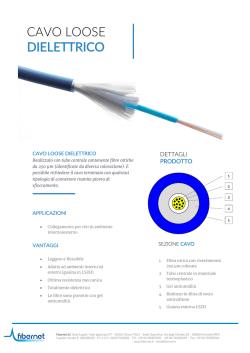
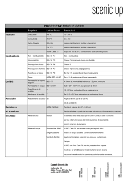
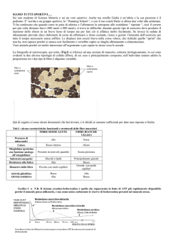
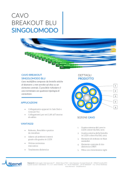
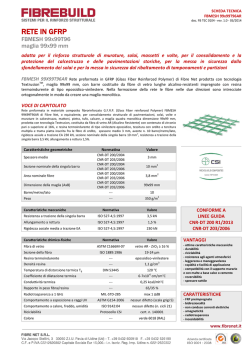
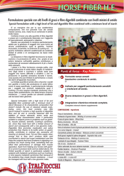
Optoelectronics Research Centre
University of Southampton
Southampton SO17 1BJ, UK
Telephone: +44 1703 593150
e-mail: [email protected]
Straight Line 10 Gb/s Soliton Transmission
over 1000 km of Standard Fibre with In-Line
Chirped Fibre Grating for Partial Dispersion Compensation
A. B. Grudinin, M. Durkin, M. Ibsen, R. I. Laming, *A. Schiffini, *P. Franco,
†E. Grandi and ’M. Romagnoli
*Pirelli Cavi s.p.a., viale Sarca 222, 20146 Milano, Italy
†Dipartimento di Elettronica, Universita di Pavia, via Ferrata 1, 27100 Pavia, Italy
’Fondazione Ugo Bordoni, via B Castiglione 59, 00142 Roma, Italy
Abstract
We demonstrate a highly practical and robust soliton transmission system with partial dispersion
compensation. Error free transmission was obtained for 10 Gb/s data over 1000km of standard fibre with
nominal dispersion of 17 ps/nm@@km. Despite variations in the dispersion compensation ratio and the relatively
high UV-induced birefringence of the fibre gratings the system exhibits BERs below 10-10 for any state of input
polarisation provided that the average intra-span dispersion is negative.
The majority of the installed fibre base has a low dispersion at wavelengths in the region of
1300nm. Upgrading to higher bit rates using erbium-doped fibre amplifiers operating around
1550nm is attractive but then the fibre dispersion imposes a severe limitation on transmission
distances. For some years there were two main approaches considered to compensate fibre
dispersion: (i) linear, based on straightforward dispersion compensation using compensating fibres
or chirped fibre gratings and (ii) non-linear, based on the use of optical solitons. Both methods
have their peculiar advantages and disadvantages. In particular linear systems suffer from fibre
nonlinearity which deteriorates the system performance at distances exceeding just 500km while
the major problems with non-linear systems are the short amplifier spacings required and
interactions between the transmitting pulses.
Fig.1 Experimental set-up.
Recent experiments have revealed that the best performance is offered by a combination of the
two methods where the first part of the intra-span distance operates in the non-linear regime
whilst the dispersion of the second (linear) part is compensated by a dispersion compensating
element [1-4]. Furthermore such hybrid systems are effective in reducing both noise- and
collision-induced timing jitters [5,6], while the Gaussian shape of the propagating pulse wings
allows higher mark-space ratios without a significant increase in soliton interaction strength [7].
1
In this Letter we present the first
experimental
results
demonstrating
straight
line
soliton transmission at 10 Gb/s
over 1000km of standard (high
dispersion) fibre with 100km
amplifier spacing and chirped fibre
gratings as the dispersion
compensating elements.
The experimental set-up is shown
in Figure 1. The soliton
transmitter is an actively modelocked fibre ring laser emitting
bandwidth limited 30ps pulses at
1549.5nm. The average output
power
was
14dBm.
Pseudorandom data is encoded on
to the pulse stream by a
Ti:LiNbO 3
Mach-Zender
modulator.
The transmission line comprises
ten ~100km spans of standard
telecommunications fibre each
followed by an erbium-doped
fibre amplifier and a chirped fibre
grating. The linearly chirped fibre
Fig.2 Typical reflection (a) and time delay (b) spectra
gratings were each 75 cm long
of linearly chirped fibre grating.
with a 4.5 nm bandwidth centred
at 1549.5nm and 90% ± 3%
reflectivity. Typical reflection and time delay spectra are shown in Figure 2. All the gratings had
the same dispersion of 1600ps/nm ± 10ps/nm. The gratings were spliced to 3-port optical
circulators with an average loss of the assembled compensators of about 4.4dB, including ~ 1.7dB
insertion loss of the circulators. Due to variations in the transmission fibre dispersion the intraspan dispersion compensation ratio varied between 89% and 99%. Quasi-random variations in
average intra-span dispersion models a practical system reasonably well. The average output
power from each amplifier (prior to the grating) was ~ 14 dBm. Polarisation mode dispersion of
the transmission fibre was less than 0.1ps/km1/2. Input pulses were pre-chirped with 2.1km of
dispersion compensating fibre with D = 60ps/nm@km.
The measured bit error rate performance (BER) is given in Figure 3 with the abscissa of the chart
being received power. The open circles show BER before and closed circles after the 1000km of
transmission. The results confirm successful transmission over 1000km with an observed power
penalty of only 3dB and there was no indication of the existence of an error floor to measured
error rates below 1@10-11. This penalty was caused mainly by signal-to-noise ration degradation
due to amplifier noise and the slightly low extinction ratio of the LiNbO3 modulator. The inset
of Fig.3 is an eye diagram at 10 Gb/s after 1000km.
2
In the course of the experiments we were able to observe the influence of the fibre gratings UV
induced birefringence [8] on the system performance. Measurements of polarisation-dependent
group velocity delay of the
gratings used in the experiment
indicated a value of 8 ± 3 ps.
After the first amplifier we have
clearly
seen
polarisation
dependent ~10ps variations in the
pulse arrival time, which however
did not result in degradation of
the BER. More significantly, the
temporal variations due to the
grating polarisation mode delay
(PMD) remains approximately
constant at 10ps up to 500km.
BER measurements at 500km,
shown in Fig.2 revealed a very
small power penalty. After
1000km of propagation variations
in the pulse arrival time increased
to ~ 20ps and BER measurements
indicated an ~ 1dB polarisation
dependence in power penalty, but
the system performance was still
essentially error-free. However
Fig.3 Error rate performance against received signal
this effect requires more
power
experimental and theoretical
Ž - back-to-back
study in order to establish the
• - after 500km
impact of PMD on the
• - after 1000km
transmission limit of soliton
Inset
shows
measured eye diagram after 1000km
systems with partial dispersion
transmission
compensation
and
further
experiments are currently in
progress.
In conclusion we have demonstrated highly practical and robust soliton transmission system with
partial dispersion compensation. Error free transmission was obtained for 10 Gb/s data over
1000km of standard fibre with nominal dispersion of 17ps/nm@km. Despite variations in the
dispersion compensation ratio and the relatively high polarisation-dependent group velocity delay
of the fibre gratings the system exhibits BERs below 10-10 for any state of input polarisation
provided that the average intra-span dispersion was negative. It was observed that overcompensation of intra-span dispersion results in a significant increase in polarisation sensitivity
and deterioration of the BER.
Acknowledgements
The authors wish to thank Prof. D.N.Payne for his continued encouragement and helpful
discussions, M.J.Cole for contribution to the grating fabrication system and F.Vaninetti for the
gratings PMD measurements. The work has been partially funded by the ESTHER contract of
3
EEC/ACTS program. The work of M.R. was done in the framework of the agreement between
FUB and the Italian PT Administration.
References
1.
Kubota, H. and Nakazawa, M., “Partial soliton communication system”, Opt. Commun.,
1992, 87, pp.15-18
2
Suzuki, M., Morita, I., Yamamoto, S., Edagawa, N., Taga, H., and Akiba, S., “Timing
jitter reduction by periodic dispersion compensation in soliton transmission”, Optical Fibre
Communications (OFC’95), 1995, San-Diego, USA, Paper PD20
3
Edagawa, N., Morita, I., Suzuki, M., Yamamoto, S., Taga, H., and Akiba, S.,“20Gb/s,
8100km straight line single channel soliton based RZ transmission experiment using
periodic dispersion compensation”, Proc. 21st European Conference on Optical
Communications (ECOC’95), Brussels, 1995, pp.983-986
4.
Le Guen, D., Favre, F., Moulinard, M. L., Henry, M., Michaud, G., Mace, L., Devaux,
F. Charbonnier, B., Georges, T., “200 Gb/s 100km-span soliton WDM transmission over
1000km of standard fibre with dispersion compensation and pre-chirping”, Optical Fibre
Communications (OFC’97), 1997, Dallas, USA, Paper PD-17
5.
Grudinin, A. B., and Goncharenko I, A., “Increased amplifier spacing in soliton system
with partial dispersion compensation”, Electron. Lett., 32, pp. 1602-1604,1996
6.
Smith, N. J. Forysiak, W., and Doran, N., “Reduced Gordon-Haus jitter due to enhanced
power solitons in strongly dispersion-managed systems”, Electron. Lett. 32, pp.20852086, 1996
7.
Smith, N.J., Knox, F.M., Doran, N. J., Blow, K. J., and Bennion, I., “Enhanced power
solitons in optical fibres with periodic dispersion management”, Electron. Lett. 32, pp. 5455, 1996
8.
Erdogan,T., and Mizrahi, V. “Characterisation of UV-induced birefringence in
photosensitive Ge-doped silica optical fibers” J. Opt. Soc. Am. B, 1994, 11, pp 21002105
4
© Copyright 2026 Paperzz