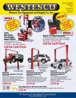
No-Slack minor repair KIT-RPR-6000L No-Slack major repair KIT-RX-67NTL For SLTPLUNT/SLTPL6000/SLTPL7000/ SLTPL7000CC top plates (left release) For SLTPLUNT/SLTPL6000/SLTPL7000/ SLTPL7000CC top plates (left release) В® В® KIT-RPR-6000R For SRTPLUNT/ SRTPL6000/ SRTPL7000 top plates (right release) See page 3 See page 3 92 Lo -50 KIT -AA Lo 00 KIT -AA -60 I -LW L-L WO CY CY L-6 10 -3 -2 L-5 AW S CY AW X L-X CY P OM L-C CY rR Air cylinder identification for air actuated top plates rR Air cylinder identification for air slide brackets Buy genuine Fontaine fifth wheel parts В® Your only source for No-Slack technology В® Contents Top plate rebuild kits Special tools. . . . . . . . . . . . . . . . . . . . . . . . . . . . . . Page 2 Top plate rebuild kits. . . . . . . . . . . . . . . . . . . . . . . . Page 2 Air cylinders for slide brackets. . . . . . . . . . . . . . . . Page 3 Air cylinders for air actuated top plates . . . . . . . . . Page 3 Fifth wheel repair kits. . . . . . . . . . . . . . . . . . . . . . . Page 3 No-SlackВ® NT 6000/7000/7000CC top plate kits . . Page 4 H5092/X5092 series top plate kits. . . . . . . . . . . . . Page 5 CD 700 series top plate kits. . . . . . . . . . . . . . . . . . Page 6 Choose the right fifth wheel . . . . . . . . . . . . . . . . Page 7-8 Brackets and mounts . . . . . . . . . . . . . . . . . . . . Page 9-17 No-SlackВ® preventive maintenance . . . . . . . . . . . Page 18 No-SlackВ® jaw and wedge adjustment. . . . . . . . . Page 19 Frequently asked questions . . . . . . . . . . . . . Pages 20-23 Troubleshooting flow charts. . . . . . . . . . . . . . . . . . . . . 24 Special tools Fontaine offers special tools for your fifth wheel to help your repairs go fast and easy. No-Slack minor rebuild kits for No-SlackВ® NT/6000/7000/ 7000CC top plates KIT-RPR-6000L (left release) KIT-RPR-6000R (right release) No-SlackВ® major rebuild kit for No-SlackВ® NT/6000/ 7000/7000CC top plates KIT-RX-67NTL No-SlackВ® test kingpin KIT-NOSLACK-KP (left release only) 5092 series spring installation tool MSC-710 NO-SLACKВ®II DISASSEMBLY All parts are to be discarded after disassembly. Degrease fifth wheel before installing new For 6000, 7000, & Ultra NT Series fifth wheels (procedures are the same). Refer to exploded view of assembly to identify item numbers and parts. Caution: Always wear safety glasses and do not stand directly over parts while disassembling or assembling wheel. NO-SLACKВ®II PARTS LIST Step 4: Unbolt the operating handle from the pivot mount and remove. NO-SLACKВ®II ASSEMBLY Before rebuilding the assembly, check to make sure that there are no cracks in the cross members or other components. Also check bracket pin holes to ensure they are not worn oversize (pins should fit snugly). Under no circumstances should a fifth wheel be repaired or used if any component (cross member, saddle bearing, etc.) is cracked. Tools Required: 1-1/16 inch wrench (wedge stop rod) 3/4 wrench and socket (bolts) Pliers (cotter pins) Step 1: Remove the secondary lock spring and the bumper spring. Remove the pull handle cotter pin and washer then, slide out the pull handle. Step 2: Unbolt and remove the secondary lock from the operating handle. Step 5: Remove the timer spring and the timer. Step 6: Remove the jaw and wedge. Item No. 1 Step 3: Unbolt and remove the bumper from the operating handle. LT-103 rebuild 9X25.indd 1 Step 7: Pull out the cotter pin and then unscrew the rod from the wedge stop nut. Remove the wedge stop rod. 1 Description Wedge Stop Rod Nut Part Number NUT-319 12 2 2 Flat Washer, 5/8", Plain WSH-304-5 3 3 Wedge Stop Rod Spring SPR-317 4 4 Wedge Stop Rod ** ROD-1108 5 5 Cotter Pin, 3/16” x 1” PIN-165 6 6 Bumper Spring SPR-374 7 7 Handle Spring SPR-338 8 8 Bushing, 5/16” BSH-629 9 9 Hex Lock Nut, 1/2” - 13, Grade “C” NUT-303-9 10 10 Bushing BSH-1225 11 Timer Spring CD-SPR-236 12 12 Step Jaw and Wedge Set WED-6000L 13 13 Bushing, 7/16” BSH-115 11 14 14 15 15 16 16 17 17 18 18 1 1 2 1 2 1 3 2 3 2 4 3 4 3 5 4 5 4 6 5 6 5 7 6 7 6 8 7 8 7 9 8 9 8 10 9 10 9 11 10 11 10 12 11 12 11 13 12 13 12 14 13 14 13 15 14 15 Quan. 14 16 15 16 1 15 17 16 17 16 2 17 18 18 1 17 19 18 19 18 1 19 20 20 19 2 20 21 21 1 20 22 21 22 21 1 22 23 23 1 22 24 23 24 23 3 24 25 25 24 1 25 26 26 1 25 27 26 27 26 1 27 28 28 27 1 28 29 29 28 30 29 30 29 31 30 31 30 32 31 32 31 33 32 33 32 34 33 34 33 34 34 1 1 2 1 2 1 3 2 3 2 4 3 4 3 5 4 5 4 6 5 6 5 7 6 7 6 8 7 8 7 9 8 9 8 10 9 10 191 10 1 1 10 12 11 12 11 13 12 13 12 14 13 14 13 15 14 Item 15 14 No. 16 15 16 15 17 16 17 16 18 17 18 17 19 18 19 18 20 19 20 19 21 20 21 20 22 21 22 21 23 22 23 22 24 23 24 23 25 24 25 24 26 25 26 25 27 26 27 26 28 27 28 27 29 28 29 28 30 29 30 29 31 30 31 30 32 31 32 31 33 32 33 32 34 33 34 33 34 34 Scan on your smartphone or tablet to view rebuild video! Step 1: Always assemble the parts around a 2” kingpin or a 2” diameter shaft. Insert the jaw first and then the wedge below it (Item Number 12). Grease the jaw and wedge on the top and bottom. Step 2: Insert the timer (Item Number 24) and the timer spring (Item Number 11). Description Part Number Quan. Flat Washer, 1/2” I.D. 1-3/8” O.D., Plain Hex Head Bolt, 1/2” -13 x 1-1/2 Grade 5 Pull Handle BLT-302-13 PUL-6000L 1 Step 4: Install the bumper (Item Number 22) and bolt to the operating handle. Use the bolt, 2 washers, lock nut and the bushing supplied in the kit (Item Numbers 21, 17, 10, 9). Note the orientation of the bolt. The bushing used in this step is the smallest of the three bushings in the bag. After installing the bumper, check to make sure that it can pivot freely. Step 5: Install the secondary lock (Item Number 20) and bolt to the operating handle. Use the bolt, 2 washers, lock nut and bushing supplied in the repair kit (Item Numbers 18, 17, 13, 9). Note the orientation of the bolt. The bushing used in this step is the medium sized bushing of the three in the bag. Step 6: Install the pull handle (Item Number 19). Use 18 the washer and cotter pin supplied in the 18 repair 18kit (Item Numbers 17, 5). Attach the handle spring 18(Item Number 7) to the secondary lock and the bumper spring (Item Number 6) to the bumper. These springs are supplied in the repair kit. Now open and close the wheel to ensure that it works properly. Ensure the fifth wheel is properly lubricated before opening and closing the wheel. 1 Secondary Lock LAT-6000L Hex Head Bolt, 1/2” -13 x 1-3/4”, Grade 5 BLT-302-14 1 Bumper BPR-6000* 1 Operating Handle OPR-6000 1 1 Timer TMR-6000L 1 Hair Pin Cotter PIN-336-1 1 Hex Head Bolt, 1/2" - 13 x 2-1/4", Grade 5 BLT-302-67 1 Step 3: Insert the operating handle (Item Number 23) and bolt to the pivot mount. Use the provided bolt, lock nut, 2 washers, hairpin cotter and the bushing supplied in the kit (Item Numbers 26, 25, 17, 13, 9). Note the orientation of the bolt. The bushing used in this step is the largest of the three bushings in the bag. Step 7: Install the wedge stop rod (Item Number 4). Use the wedge stop rod nut and spring, as well as the 2 washers and a cotter pin (Item Numbers 1, 2, 3, 5). Note that the spring is placed between the 2 washers and the cotter pin is inserted through the rod behind the first washer. The rod is then screwed into the nut. Close the fifth wheel several times with a standard 2” kingpin tool. With the lock closed, adjust the wedge stop rod so that the end is 1/4 inch from the wedge. 18 4/10/13 1:06 PM Seven kits combined in one to save you time and money. Complete instructions for disassembly and reassembly – don’t waste time wondering what to do. Parts are arranged in the sequence you need them – the part you need is QR code links to instructional video – have questions answered within reach. 19 19 20 20 21 21 22 22 For kit information on obsolete products go to www. fifthwheel.com Choose Support at top menu and choose Obsolete products 23 23 24 24 25 25 26 26 27 27 28 28 29 29 30 30 31 31 32 32 33 33 34 34 and repair with confidence 2 800-874-9780 • www.fifthwheel.com Buy genuine Fontaine fifth wheel parts В® Your only source for No-Slack technology В® Air cylinders for air slide brackets Fifth wheel repair kits CYL-COMP 12-1/4" 7000 and 6000 fifth wheel kits Minor rebuild kit road side release......KIT-RPR-6000L Major rebuild kit road side release........KIT-RX-67NTL Rebuild kit curb side release.............. KIT-RPR-6000R Wedge-stop rod................................... KIT-ROD-1108 Bracket pin (one-piece bushing) .............KIT-PIN-191 Bracket pin (two-piece bushing)..............KIT-PIN-LLB Secondary lock............................ KIT-LAT-6000L or R Spring kit..................................................KIT-SPRING Bumper kit...................................KIT-BPR-6000L or R Timer..........................................KIT-TMR-6000L or R Operating handle................................. KIT-OPR-6000 Pull handle...................................KIT-PUL-6000L or R Air actuated...................................KIT-AA-6000L or R 7/8" diameter holes CYL-XAWX 12-1/4" 1/2" diameter holes CYL-5AWS-2 24-3/8" 7/8" diameter holes CYL-610-3 7000CC fifth wheel kits 24-3/8" Minor rebuild kit road side release......KIT-RPR-6000L Major rebuild kit road side release........KIT-RX-67NTL Wedge-stop rod................................... KIT-ROD-1108 Bracket pin (one-piece bushing)..............KIT-PIN-191 Bracket pin (two piece bushing)...............KIT-PIN-LLB Secondary lock....................................KIT-LAT-6000L Spring kit..................................................KIT-SPRING Bumper kit..........................................KIT-BPR-6000L Timer................................................. KIT-TMR-6000L Operating handle................................. KIT-OPR-6000 Pull handle.......................................... KIT-PUL-6000L Air actuated..........................................KIT-AA-6000L Clean Connect plates......................CCR-Plates-L or R 9/16" diameter hole CYL-LWS 23-7/8" .98" diameter hole CYL-LWO-LWI 21.30" .41" diameter hole No-SlackВ® NT fifth wheel kits Air cylinders for air actuated top plates Minor rebuild kit road side release..... KIT-RPR-6000L Major rebuild kit road side release....... KIT-RX-67NTL Wedge-stop rod...................................KIT-ROD-1108 Bracket pin.............................................KIT-PIN-UNT Secondary lock................................... KIT-LAT-6000L Spring kit................................................. KIT-SPRING Bumper kit......................................... KIT-BPR-6000L Timer.................................................KIT-TMR-6000L Operating handle................................. KIT-OPR-6000 Pull handle..........................................KIT-PUL-6000L Air actuated......................................... KIT-AA-6000L KIT-AA-6000L or R 17-3/8" 1/2" diameter holes KIT-AA-5092L or R 15" 1/2" diameter holes H5092 and X5092 fifth wheel kits Air line kits Rebuild kit road side release...............KIT-RPR-5092L Rebuild kit curb side release.............. KIT-RPR-5092R Wedge-stop rod................................... KIT-ROD-1108 Bracket pin (H5092 models).....................KIT-PIN-191 Bracket pin (X5092 models).................... KIT-PIN-XHD Pull handle............................................KIT-PUL-5092 Timer............................................KIT-TMR-134L or R Bumper kit (H5092 models).........KIT-BPR-5092L or R Bumper kit (X5092 models)...........KIT-BPR-131L or R Operating handle.........................OPR-5000-SL or SR KIT-AIR-DASH Kit to complete the in-dash installation. KIT-AIR-COIL Kit to connect the air actuated fifth wheel or fifth wheel air sliders to the air system. 800-874-9780 • www.fifthwheel.com 3 No-SlackВ® NT/6000/7000/7000CC series top plate kits KIT-PIN-191 (pair) 9 8 24 18 23 25 20 22 21 20 19 Use if on a AWB, MWS, AWX, PSA, XAWX mount 17 15 11 13 29 Clean Connect plates can only be used with the 7000CC fifth wheel top plate. 31 27 7 26 KIT-PIN-LLB 30 (pair) 6 28 Use if on LWB, ATB, MTB, BSM, PMA mount 16 32 14 33 34 12 48 33 These kits can only be used with the 7000CC Clean Connect fifth wheel top plate. ItemDescription Quantity (CCR-PLATES-R) 46 Right CC plate 1 48 Flat washer 7 49 Hex lock nut 7 (CCR-PLATES-L) 47 Left CC plate 1 48 Flat washer 7 49 Hex lock nut 7 37 39 4 2 3 2 40 1 45 41 42 Rebuild kit (KIT-RPR-6000L or R) ItemDescription 10 Bumper spring 11 Handle spring 37 Timer spring 38 Step jaw 39 Wedge 21 Bushing, 7/16" 34 Bushing, 5/16" 43 Bushing, 1 1/4" 23 32 41 Hex lock nut, 1/2" - 13 Quantity 1 1 1 1 1 1 1 1 3 Wedge-stop rod kit (KIT-ROD-1108) 1 2 3 4 5 Wedge-stop rod nut Flat washer, 5/8" I.D. Wedge-stop rod spring Wedge-stop rod Cotter pin, 3/16" x 1" 1 2 1 1 1 Bracket pin kit (KIT-PIN-191) 6 7 8 9 Use if mounted 2 1-piece bushing to AWB, MWS, 2 Bracket pin Bracket retainer pin AWX, PSA, 2 XAWX Cotter pin 2 Bracket pin kit (KIT-PIN-LLB) 27 2-piece bushing 28 Bracket pin 29 Bracket retainer pin 30 Cotter pin 31 Bracket liner 2 Pairs Use if 2 mounted to 2 LWB, MTB, BSM, ATB, 2 PMA 2 Secondary lock kit (KIT-LAT-6000L or R) 11 19 20 21 22 23 26 4 Handle spring Hex head bolt, 1/2" - 13 Flat washer, 1/2" I.D. Bushing, 7/16" Secondary lock Hex lock nut, 1/2" - 13 Cotter pin, 3/16" x 1" 1 1 2 1 1 1 1 43 44 42 Spring kit (KIT-SPRING) ItemDescription 10 Bumper spring 11 Handle spring 37 Timer spring 49 Clean Connect plate kits 38 5 7 per side 35 36 10 47 46 No-SlackВ® NT plates only use the following bracket pin kit 50 54 Quantity 1 1 1 52 53 51 Bracket pin kit (KIT-PIN-UNT) Bumper kit (KIT-BPR-6000L or R) 32 Hex lock nut, 1/2" - 13 33 Flat washer, 1/2" I.D. 34 Bushing 35 Hex head bolt, 1/2" - 13 36 Bumper 10 Bumper spring 1 2 1 1 1 1 Timer kit (KIT-TMR-6000L or R) 37 Timer spring 1 40 Timer 1 41 Hex lock nut, 1/2" - 131 Hair pin cotter (not pictured) 1 Operating handle kit (KIT-OPR-6000) 21 34 43 Bushing, 7/16" Bushing, 5/16" Bushing, 1 1/4" 23 32 41 Hex lock nut, 1/2" - 13 42 Flat washer, 1/2" I.D. 44 Hex head bolt, 1/2" В- 13 45 Operating handle Hair pin cotter (not pictured) 1 1 1 3 2 1 1 1 Pull handle kit (KIT-PUL-6000L or R) 24 25 26 Pull handle Flat washer, 1/2" I.D. Cotter pin, 3/16" x 1" 1 1 1 800-874-9780 • www.fifthwheel.com 50 51 52 53 54 1-piece bushing Bracket pin Bracket retainer pin Cotter pin Bracket Liner 2 2 2 2 2 Air actuated kit (KIT-AA-6000L or R) This kit includes the parts mounted to the fifth wheel. If you are upgrading from manual to air actuated you will also need KIT-AIR-DASH which includes the parts required to complete the in-dash installation. ItemDescription Quantity 12 Hex head bolt 1 13 Hex lock nut 1 14 Air cylinder 1 15 Mini-matic jumbo exhaust valve1 16 Hex lock nut 1 17 Flat washer 1 18 Shoulder bolt 1 KIT-AIR-DASH KIT-AIR-COIL Parts required to connect the air actuated fifth wheel or fifth wheel air sliders to the air system. H5092/X5092 series No-SlackВ® top plate kits 14 10 15 11 9 12 16 8 13 7 14 6 17 9 15 18 8 6 7 21 19 20 22 23 24 5 25 4 3 2 27 1 2 26 Rebuild kit (KIT-RPR-5092L or R) ItemDescription 12 Step jaw 13 Wedge 14 Jaw and wedge spring 15 Cotter pin, 1/4" x 3" 19 Bumper spring 22 Bushing, 5/16" 28 Bushing, 7/16" 24 Hex lock nut, 1/2" - 13 26 Hex lock nut, 1/2" - 13 Quantity 1 1 2 2 1 1 1 1 1 Pull handle kit (KIT-PUL-5092) ItemDescription 10 Leaf spring 11 Self tapping screw 17 Pull handle 18 Cotter pin, 3/16" x 1" 21 Flat washer, 1/2" I.D. Timer kit (KIT-TMR-134L or R) Wedge-stop rod kit (KIT-ROD-1108) ItemDescription 1 Wedge-stop rod nut 2 Flat washer, 5/8" I.D. 3 Wedge-stop rod spring 4 Wedge-stop rod 5 Cotter pin, 3/16" x 1" Bracket pin kit (KIT-PIN-191) ItemDescription 6 1-piece bushing 7 Bracket pin 8 Bracket retainer pin 9 Cotter pin Quantity 1 2 1 1 1 ItemDescription 16 Timer 22 Bushing 5/16" 24 Hex lock nut, 1/2" - 13 28 Bushing 7/16" 26 Hex lock nut, 1/2" - 13 Quantity 1 1 1 1 1 Quantity 1 1 1 1 1 ItemDescription 6 1-piece bushing 7 Bracket pin 8 Bracket retainer pin 9 Cotter pin 30 Bumper kit (KIT-BPR-5092L or R) ItemDescription 25 Bumper 19 Bumper spring 22 Bushing 5/16" 24 Hex lock nut, 1/2" - 13 30 Hex head bolt, 1/2" - 13 29 Flat washer, 1/2" I.D. 28 Bushing 7/16" 26 Hex lock nut, 1/2" - 13 ItemDescription 27 Operating handle 20 Hex head bolt, 1/2" - 13 22 Bushing 5/16" 23 Flat washer, 1/2" I.D. 24 Hex lock nut, 1/2" - 13 30 Hex head bolt, 1/2" - 13 29 Flat washer, 1/2" I.D. 28 Bushing 7/16" 26 Hex lock nut, 1/2" - 13 Quantity 2 2 2 2 Quantity 1 2 1 1 1 1 1 1 Note: For XtraВ® heavy duty models choose KIT-BPR-131L or R Operating handle kit (KIT-OPR-5000-SL OR SR) Use on AWB, PSA, FMA mounts Bracket pin kit (KIT-PIN-XHD) 29 28 Quantity 1 1 1 1 1 1 1 1 1 Quantity 2 2 2 2 Use on XAWX, XPSA mounts 800-874-9780 • www.fifthwheel.com 5 CD 700/600 series custom duty top plate kits 10 12 11 9 8 13 7 8 5 7 2 16 6 5 4 1 6 14 15 16 3 17 7 26 20 19 25 18 27 21 22 28 23 24 Rebuild kit (KIT-RPR-S500) ItemDescription Quantity 4 Jaw spring 1 7 Cotter pin, 3/16" x 1" 3 9 Pull handle spring set 1 15 Bushing, 7/16" 1 16 Hex head flanged bolt, nut 1 17 Flat head socket, 5/8"-11 x 3-1/2", grade 5 1 18 Jaw and wedge set 1 19 Bushing 1 21 Flat washer, 5/8", plain 1 22 Hex lock nut, 5/8" -11, grade "B" 1 23 Cotter pin, 5/32" x 1" 1 24 Flat washer 3/4", plain 1 25 Clevis pin, 3/4" x 3" 1 28 Wedge-stop rod guide 1 Wedge-stop rod kit (KIT-CD-ROD) ItemDescription 1 Wedge-stop rod 2 Wedge-stop rod nut 3 Wedge-stop rod spring Quantity 1 1 1 Wedge-stop rod guide kit (KIT-CD-STOP) ItemDescription Quantity 26 Hex lock nut, 3/8" -16, grade 5 2 27 Wedge-stop rod guide 1 28 Hex head bolt, 3/8" -16 x 1", grade 2 2 Bracket pin kit (KIT-CD-PIN-224) ItemDescription 5 Bracket pin 6 Bracket bushing 7 Cotter pin, 3/16" x 1" 8 Bracket retainer pin Quantity 2 2 2 2 Lock pin kit for 700 (KIT-CD7-LOCKPIN) Lock pin kit for 600 (KIT-CD6-LOCKPIN) ItemDescription 10 Lock pin 11 Hair pin cotter 12 Chain ItemDescription Quantity 7 Cotter pin, 3/16" x 1" 3 10 Lock pin 1 11 Hair pin cotter 1 12 Chain 1 13 Handle grip 1 14 Pull handle 1 15 Bushing, 7/16" 1 16 Hex head flanged bolt, nut 1 17 Flat head socket, 5/8"-11 x 3-1/2", grade 5 1 19 Bushing 1 20 Operating handle 1 21 Flat washer, 5/8", plain 1 22 Hex lock nut, 5/8" -11, grade "B" 1 23 Cotter pin, 5/32" x 1" 1 Quantity 1 1 1 Custom Duty Assemblies Custom Duty Service Parts SLCD7FM5750*. . . CD700 with bracket for stationary mounting SLCD7PA6125*. . . . CD700 with a 6.125" plate mount CD7AWB675024. . . CD700 with a 6.75" air slide bracket and 24" slide rail *Some welding required. SLTPLCD700. . . . . . BKTCDPLT. . . . . . . BKTCD. . . . . . . . . . CDBKTAWB6PT. . . . CDASYAWB624. . . . CDSLR24B. . . . . . . CYL-COMP. . . . . . . KIT-AWB-WEDGE . . 6 Handle kit for 700 (KIT-CD-7HDL) Handle kit for 600 (KIT-CD-6HDL) CD700 replacement fifth wheel top plate Bracket and plate for the SLCDPA6125 Bracket for the SLCD7FM5750 CD air slide bracket 6.75" height 6.75" CD AWB bracket with a 24" CD slide rail 24" CD side rail AWB air cylinder Locking wedge (pair) 800-874-9780 • www.fifthwheel.com Choosing the right fifth wheel – top plate styles No-SlackВ® NT (Driver side; SLTPLUNT • Air Actuated; AATPLUNT) 50,000 pounds vertical load. 150,000 pounds drawbar pull. The new No-SlackВ® NT is designed for 100% on-highway standard duty applications. The stamped steel fifth wheel features the patented self-adjusting No-SlackВ® locking mechanism with a positive secondary lock that can only be released by pulling the handle. A safety trigger eliminates the possibility of false couplings to prevent dangerous high hitching. The pull force required to open the lock is only 65 lbs. The No-SlackВ® NT also features savings of up to 50 lbs or more over competitive products–helps fleets offset heavy 2010 emission system components. Optional air actuation with in-cab air release (operates only when parking brake is engaged). Rated for on-highway use only, including tankers. Only weighs about 228 lbs. Only use on LWO, LWI, ASB, APB or SMB mounts. No-SlackВ® 6000 series (Driver side; SLTPL6000 • Passenger side; SRTPL6000 • Air Actuated; AATPL6000) 50,000 pounds vertical load. 150,000 pounds drawbar pull. The innovative 6000 series fifth wheel is designed for standard and moderate duty appliВcations. It features the patented self-adjusting No-SlackВ® locking mechanism with a positive secondary lock that can only be released by pulling the handle. A safety trigger eliminates the possibility of false couplings to prevent dangerous high hitching. No-SlackВ® 7000 series (Driver side; SLTPL7000 • Passenger side; SRTPL7000 • Air Actuated; AATPL7000) 55,000 pounds vertical load. 150,000 pounds drawbar pull. The 7000 series offers all the benefits of our 6000 series, but in a cast design rather than pressed steel. It features the patented self-adjusting No-SlackВ® locking mechanism with a positive secondary lock that can only be released by pulling the handle. A safety trigger eliminates the possibility of false couplings to prevent dangerous high hitching. 7000 series is also available as a blocked fifth wheel in a variety of sizes to cover more frameless dump applications. No-SlackВ® 7000CC series Clean-Connect (Driver side; SLTPL7000CC • Air Actuated; AATPL7000CC) 55,000 pounds vertical load. 150,000 pounds drawbar pull. The 7000CC series Clean-Connectв„ў offers all the benefits of our 7000 series fifth wheels plus the added benefit of a grease free top plate surface. With Clean-Connectв„ў technology the fifth wheel no longer requires grease to lubricate between the top plate surface and the trailer coupling plate. This eliminates the labor costs, materials and downtime associated with greasing the top plate surface. No-SlackВ® H5092 Series (Driver side; SLTPLH5092 • Passenger side; SRTPLH5092 • Air Actuated; AATPLH5092) 62,500 pounds vertical load. 150,000 pounds drawbar pull. The H5092 Series fifth wheel is designed for applications such as logging, chip hauling and end dump trailers. This rugged fifth wheel uses a patented self-adjusting No-Slack locking mechanism. Special steel cross members reinforce this wheel to reduce damaging fifth wheel flex under heavy loads. В® No-SlackВ® X5092 Series (Driver side; SLTPLX5092 • Passenger side; SRTPLX5092) 75,000 pounds vertical load. 200,000 pounds drawbar pull. The X5092 Series fifth wheel is designed for severe service applications. It offers the same great features as the H5092 Series, plus additional steel reinforcement for even greater capacity. 800-874-9780 • www.fifthwheel.com 7 Choosing the right fifth wheel With the Fontaine Fifth Wheel complete product line you can easily select the perfect fifth wheel for your application. We offer top plates and mounting options in a wide variety of sizes to handle even the most demanding applications. To specify the right fifth wheel for your application two factors must be considered: load capacity and service conditions. “Weight” refers to the amount of weight that a fifth wheel can handle. “Road type” refers to the operating environment and the type of equipment used in an application. “Travel type” refers to mileage between stops. You don’t choose a top plate based on “weight” only. Consider service conditions because a heavy load pulled on a paved road places less stress on a fifth wheel than a lighter load pulled in severe off-highway conditions. For more information on top plate selection please refer to LT-076: Application guide available at fifthwheel.com. Choose “Support and then choose “Choosing the Right Fifth Wheel.” If you need further assistance contact Fontaine Parts Connection at 800-874-9780. Duty class restrictions Standard duty Weight: Less than 95,000 lbs (43,000 kgs) gross combination weight (GCW) Road type: 100% on-highway application on maintained concrete or asphalt roads. Travel type: More than 30 miles between each stop. Axle limitation: Maximum number of towed axles equals 2. Moderate duty (on-highway) Weight: Less than 115,000 lbs (52,000 kgs) gross combination weight (GCW) Road type: 100% on-highway application on maintained concrete or asphalt roads. Travel type: No minimum mileage between stops. Axle limitation: Maximum number of towed axles equals 4. Moderate duty (off-highway) Weight: Less than 115,000 lbs (52,000 kgs) gross combination weight (GCW) Road type: Less than 10% off-highway application on maintained concrete, asphalt, gravel or crushed rock roads. Travel type: No minimum mileage between stops. Axle limitation: Maximum number of towed axles equals 4. Severe duty (on-highway) Weight: More than 115,000 lbs (52,000 kgs) gross combination weight (GCW) Road type: Less than 10% Off-Highway application on maintained concrete, asphalt, gravel or crushed rock roads. Travel type: No minimum mileage between stops. Axle limitation: No axle limitations Severe duty (off-highway) Weight: More than 115,000 lbs (52,000 kgs) gross combination weight (GCW) Road type: Any off-highway application on all road types including non-maintained roads. Travel type: No minimum mileage between stops. Axle Limitation: No axle limitation. Special applications: 8 All logging, mining and oil field applications fall into this category regardless of anticipated weight, road type or number of axles. 800-874-9780 • www.fifthwheel.com LWB light weight air slide bracket 10 9 10 9 8 19 10 14 9 8 7 10 11 14 9 15 7 11 21 15 13 Rebuild kit (KIT-LWB) 20 16 17 18 16 12 17 22 4 7 20 6 7 8 2 3 8 18 22 5 1 4 3 2 ItemDescription 2 BSH-109 3 BSH-172 4 LNR-107 7 BLT-101-4 8 BSH-115 9 WSH-104-4 10 NUT-103-6 11 LOC-388 12 LOC-347-1 13 LOC-347-2 14 BLT-102-77 15 BSH-316 16 WSH-104-2 17 NUT-103-17 18 BLT-102-11 19 CYL-COMP 20 SPR-327 21 WSH-104-21 22 WSH-104-3 Quantity 2 2 2 4 4 4 4 2 1 1 2 2 2 2 2 1 2 2 2 1 LWB Parts Item 1 2 3 4 5 6 7 8 9 10 11 12 13 14 15 16 17 18 19 20 21 22 Air slide bracket Mounted Description Rear slide stop Lower bracket bushing (pr.) Upper bracket bushing (pr.) Bracket liners Slide bracket (see slide bracket chart at right) Slide rail (see slide rail chart) Flat head bolt, 1/2"-13 x 1-3/4" Spacer bushing Flat washer, 1/2" I.D., 1-3/8" O.D., plain Hex nut, lock 1/2"-13, low profile Linkage, LWB Locking wedge, left Locking wedge, right Hex head bolt, 3/8” 16 x 1-1/4”, grade 5 Bushing Flat washer, 3/8" I.D.,1" O.D., plain Hex nut lock, 3/8-16 Hex head bolt, 1/2"-13x1-1/4”, grade 5 Air cylinder CYL-COMP Spring Flat washer, 3/8”, fender Flat washer, 1/2” I.D., 1" O.D., plain Quantity 2 2 2 2 1 1 4 4 4 4 2 1 1 2 2 2 2 2 1 2 2 2 Item 2 to 2 to 2 to 2 to 2 to 5 5 5 5 5 and and and and and 7 7 7 7 7 to to to to to 21 21 21 21 21 Part Number Height BKTLWB6PT 6-3/4" BKTLWB7PT 7-1/4" BKTLWB8PT 8-1/4" BKTLWB9PT 9-1/4" BKTLWB10PT 10-1/4" Slide rails Slide Mounted Items Part Number Travel Length 1 to 6 SLRLWB12 12" 32" 1 to 6 SLRLWB16 16" 38" 1 to 6 SLRLWB24 24" 44" 1 to 6 SLRLWB3636" 55" 1 to 6 SLRLWB4848" 67" Bracket pin kit (KIT-PIN-LLB) 2 3 4 2-piece bushing Bracket pin Bracket retainer pin Cotter pin Bracket liner 2 Pairs 2 2 2 2 Other kits for LWB Rebuild kit . . . . . . . . . . . . . . . . . . . . . . . . . . . . . . . . . . . . . KIT-LWB Locking wedge kit for LWB. . . . . . . . . . . . . . . . . . . . . . . . . KIT-LWB-WEDGE Air cylinder. . . . . . . . . . . . . . . . . . . . . . . . . . . . . . . . . . . . . CYL-COMP Air cylinder connection kit. . . . . . . . . . . . . . . . . . . . . . . . . . KIT-AIR-COIL Air installation kit. . . . . . . . . . . . . . . . . . . . . . . . . . . . . . . . KIT-AIR Bushings . . . . . . . . . . . . . . . . . . . . . . . . . . . . . . . . . . . . . . BSH-LLB Mounting bolt kit (up to 24" slide travel). . . . . . . . . . . . . . . KIT-SLD-1824 Slide limit blocking kit. . . . . . . . . . . . . . . . . . . . . . . . . . . . . KIT-SLS-LWB 800-874-9780 • www.fifthwheel.com 9 LWO light weight outboard slide 7 8 7 6 Air slide bracket Mounted 5 Item 3 , 4 and 3 , 4 and 3 , 4 and 9 8 6 9 to to to 11 11 11 Part Number Height BKTLWO6PT6-3/4" BKTLWO7PT7-3/4" BKTLWO8PT8-3/4" Slide rails Slide Items 2 & 3 2 & 3 2 & 3 2 & 3 2 & 3 4 10 11 1 3 2 4 Bracket pin and bushing kit (KIT-PIN-UNT) Mounting bolt kit (KIT-SLD-1824) LWO Parts Item 1 2 3 4 5 6 7 8 9 10 11 Part Number Travel Length SLRLWO1212" 31" SLRLWO1616" 35" SLRLWO2424" 43" SLRLWO3636" 55" SLRLWO4848" 67" Description Quantity 4 KIT-PIN-UNT (No-SlackВ® NT) 2 2 Description Slide rail Rear slide stop Slide bracket (see slide bracket chart ) Bracket Bushing Air Cylinder Locking Wedge Hex Bolt, 3/8-16 x 1.25" Spacer Bushing Lock Nut, 3/8-16 Flat Washer, 1/2" Hex Head Bolt, 1/2-13 x 1.00 Quantity 1 2 1 2 1 2 2 2 2 2 2 Other kits for LWO Air cylinder. . . . . . . . . . . . . . . . . . . . . . . . . . . . . . . . . . . . . CYL-LWO-LWI Air cylinder connection kit. . . . . . . . . . . . . . . . . . . . . . . . . . KIT-AIR-COIL Air installation kit. . . . . . . . . . . . . . . . . . . . . . . . . . . . . . . . KIT-AIR Locking wedge kit . . . . . . . . . . . . . . . . . . . . . . . . . . . . . . . KIT-LOC-LWO Bushings . . . . . . . . . . . . . . . . . . . . . . . . . . . . . . . . . . . . . . BSH-3000 Mounting bolt kit (up to 24" slide travel). . . . . . . . . . . . . . . KIT-SLD-1824 10 5 5 5 800-874-9780 • www.fifthwheel.com DescriptionQuantity BLT-302-252 BLT-302-2716 NUT-303-318 WSH-304-736 ATB air slide bracket and rails 19 21 19 21 18 20 21 17 19 21 17 18 16 21 15 21 19 17 14 13 12 17 9 11 19 21 19 21 10 11 17 7 8 8 Rebuild kit (KIT-ATB) 4 7 10 3 2 ItemDescription 7 BLT-301-5 8 BLT-301-2 9 BLT-301-3 10 BLT-302-12 11 LOC-287 12 LOC-683 13 LOC-664 14 LEV-686 15 SPR-632 16 CYL-COMP 17 BSH-629 18 NUT-303-9 19 NUT-303-6 10 WSH-304-4 Quantity 2 1 1 1 2 1 1 1 2 1 5 4 3 6 6 Air slide bracket Mounted 5 1 4 3 ASYATB824 (3-3/4" height, 24" travel shown) 1 2 ATB Parts Item 1 2 3 4 5 6 7 8 9 10 11 12 13 14 15 16 17 18 19 20 21 Description Rear slide stop Lower bracket bushing (pr.) Upper bracket bushing (pr.) Bracket liners Slide bracket (see slide brackets at right) Slide rail (see slide rails at right) Flat head socket, 1/2" -13 x 2", grade 5 Flat head socket, 1/2" -13 x 1", grade 5 Flat head socket, 1/2" -13 x 1-1/2", grade 5 Hex head bolt, 1/2" -13 x 1", grade 5 Locking wedge (pr.) Locking wedge release bar Locking wedge release bar Latching lever Locking member spring Air cylinder Bushing, 5/16" Bushing, 7/16" Hex lock nut, 1/2" -13, grade "C" Hex jam nut, 1/2" -13, grade "B" Flat washer, 1/2" I.D., 1-3/8" O.D., plain Quantity 2 1 1 2 1 1 2 2 1 2 1 1 1 1 2 1 5 2 4 3 8 Item 2 to 2 to 2 to 2 to 2 to Part Number Height 5 5 5 5 5 and and and and and 7 7 7 7 7 to to to to to 21 BKTATB6PT 6-3/4" 21 BKTATB7PT 7-3/4" 21 BKTATB8PT 8-3/4" 21 BKTATB9PT 9-3/4" 21 BKTATB10PT10-3/4" Slide rails Slide Items 1 and 1 and 1 and 1 and 1 and 6 6 6 6 6 Part Number Travel Length SLRTB1212"39.63" SLRTB1616"45.38" SLRTB2424"51.63" SLRTB3636"63.63" SLRTB4848"75.63" Bracket pin kit (KIT-PIN-LLB) 2 3 4 2-piece bushing Bracket pin Bracket retainer pin Cotter pin Bracket liner 2 Pairs 2 2 2 2 Mounting bolt kit (KIT-SLD-1824) DescriptionQuantity BLT-302-252 BLT-302-2716 NUT-303-318 WSH-304-736 Other kits for ATB Slide limit blocking kit. . . . . . . . . . . . . . . . . . . . . . . . . . . . KIT-SLS-ATB Air cylinder (CYL-5AWB-1 is superseded to CYL-COMP) . . CYL-COMP Air cylinder connection kit. . . . . . . . . . . . . . . . . . . . . . . . . KIT-AIR-COIL Air installation kit. . . . . . . . . . . . . . . . . . . . . . . . . . . . . . . KIT-AIR Bushings . . . . . . . . . . . . . . . . . . . . . . . . . . . . . . . . . . . . . BSH-LLB Mounting angles 3/8" 3"x 4" (up to 24" slide travel). ANGP55B175 The ATB and AWB are not interchangeable. The ATB can be identified by the 2" slide increments and forked locking wedge. 800-874-9780 • www.fifthwheel.com 11 AWB air slide bracket and rails 7 16 9 7 16 12 16 14 17 13 8 7 16 13 19 7 16 9 7 16 16 14 7 15 16 13 Rebuild kit (KIT-AWB) ItemDescription 5 BLT-301-5 6 KIT-AWB-WEDGE 7 NUT-303-9 8 CYL-COMP 10 BLT-301-2 11 BLT-301-12 12 NUT-303-6 13 BSH-629 14 SPR-632 15 LOC-664 16 WSH-304-4 17 LOC-683 18 LEV-686 6 13 5 10 18 13 10 6 11 5 11 4 2 Air slide bracket Mounted Item 2 2 2 2 2 1 3 1 and and and and and 5 5 5 5 5 to to to to to 18 18 18 18 18 Part Number Height BKTAWB6PT6-3/4" BKTAWB7PT7-3/4" BKTAWB8PT8-3/4" BKTAWB9PT9-3/4" BKTAWB10PT10-3/4" Slide rails AWB Parts Description Rear slide stop Bracket bushing (pr.) Slide bracket (See slide brackets at right) Slide rail (See slide rail at right) Flat head socket, 1/2" -13 x 2", grade 5 Locking wedge (pr.) Hex lock nut, 1/2" -13, grade "C" Air cylinder Bushing, 7/16" Flat head socket, 1/2" -13 x 1", grade 5 Hex head bolt, 1/2" -13 x 1", grade 5 Hex jam nut, 1/2" -13, grade "B" Bushing, 5/16" Locking member spring Locking wedge release bar Flat washer, 1/2" I.D., 1-3/8" O.D., plain Locking wedge release bar Latching Lever Flat head socket, 1/2"-13 x 1-1/2", grade 5 Quantity 2 1 1 1 2 1 4 1 2 2 2 3 5 2 1 8 1 1 1 Other kits for AWB Air cylinder (CYL-5AWB is superseded to CYL-COMP). CYL-COMP Air installation kit. . . . . . . . . . . . . . . KIT-AIR Bushings . . . . . . . . . . . . . . . . . . . . . . . . . . . . . . . . . . BSH-150 Mounting angles Pins and bushings . . . . . . . . . . . . . . . . . . . . . . . . . . . KIT-PIN-191 3/8" 3"x 4" (up to 24" slide travel). . ANGP55B175 Air cylinder connection kit. . . . . . . . . . . . . . . . . . . . . . KIT-AIR-COIL Note: The AWB has been replaced by the ATB. The ATB and AWB are not interchangeable. The AWB can be identified by the 4" slide increments and single locking wedge. 3000 series top plates do not fit on AWB brackets. 12 3 3 3 3 3 ASYAWB824 (8-3/4" height 24" travel shown) 2 Item 1 2 3 4 5 6 7 8 9 10 11 12 13 14 15 15 16 17 18 Quantity 2 1 2 1 2 1 3 5 2 1 6 1 1 KIT-AWB-WEDGE 800-874-9780 • www.fifthwheel.com Slide Mounted Items Part Number Travel Height 1 to 4 & 7 SLR12B 12" 42" 1 to 4 & 7 SLR16B 16" 46" 1 to 4 & 7 SLR24B 24" 54" 1 to 4 & 7 SLR36B 36" 66" 1 to 4 & 7 SLR48B 48" 78" Bracket pin kit (KIT-PIN-191) 2 1-piece bushing Bracket pin Bracket retainer pin Cotter pin Mounting bolt kit (KIT-SLD-1824) 2 2 2 2 DescriptionQuantity BLT-302-252 BLT-302-2716 NUT-303-318 WSH-304-736 MWS manual slide bracket and rails 7 16 18 8 7 9 7 7 7 16 7 16 16 15 13 16 14 14 7 13 Slide bracket 13 17 19 Mounted Item Part Number Height 2 3 and 5 to 19 BKTMWS7PT7-3/4" 2 3 and 5 to 19 BKTMWS8PT8-3/4" 2 3 and 5 to 19 BKTMWS9PT9-3/4" 2 3 and 5 to 19 BKTMWS10PT10-3/4" 6 13 13 10 13 10 5 11 6 5 Slide rails Slide Mounted 2 4 2 1 ASYMWS824 (8-3/4" height, 24" slide travel shown) DescriptionQuantity BLT-302-252 BLT-302-2716 NUT-303-318 WSH-304-736 Bracket pin kit (KIT-PIN-191) MWS Parts Item 1 2 3 4 5 6 7 8 9 10 11 12 13 14 15 16 17 18 19 Mounting bolt kit (KIT-SLD-1824) 1 3 Items Part Number Travel Height 1 to 4 SLR12B 12" 42" 1 to 4 SLR16B 16" 46" 1 to 4 SLR24B 24" 54" 1 to 4 SLR36B 36" 66" 1 to 4 SLR48B 48" 78" Description Rear slide stop Bracket bushing (pr.) Slide bracket (Slide bracket above) Slide Rail (See slide rail above) Flat head socket, 1/2" -13 x 2", grade 5 Locking wedge (pr.) Hex lock nut, 1/2" -13, grade "C" Pull handle Flat head socket, 1/2" -13 x 1-1/2", grade 5 Flat head socket, 1/2" -13 x 1", grade 5 Hex head bolt, 1/2" -13 x 1", grade 5 Hex jam nut, 1/2" -13, grade "B" Bushing, 5/16" Locking member spring Locking wedge release bar Flat washer, 1/2" I.D., 1-3/8" O.D., plain Locking wedge release bar Latching lever spring Latching lever Quantity 2 1 1 1 2 1 3 1 1 2 1 3 6 2 1 6 1 1 1 2 1-piece bushing Bracket pin Bracket retainer pin Cotter pin 2 2 2 2 Mounting angles 3/8" 3"x 4" (up to 24" slide travel). . ANGP55B175 Note: The MWS has been replaced by the MTB. The MTB and MWS are not interchangeable. The MWS can be identified by the 4" slide increments and single locking wedge. 3000 series top plates do not fit on MWS brackets. 800-874-9780 • www.fifthwheel.com 13 AWX air slide bracket and rails 17 10 19 16 10 17 10 18 8 19 16 10 19 18 16 8 9 17 10 16 22 14 Slide bracket Mounted 15 19 11 16 14 9 10 16 9 19 16 21 18 13 16 19 17 21 13 13 5 6 5 6 5 6 9 16 19 20 Item 10 19 Part Number Height and and and 8 8 8 to to to 22 BKTAWX9PT9-1/2" 22 BKTAWX10PT10-1/2" 22 BKTAWX11PT11-1/2" 8 Slide rails Slide Mounted 14 Items Part Number Travel 1 to 4 & 7 SLR12X 12" 1 to 4 & 7 SLR24X 24" 1 to 4 & 7 SLR36X 36" 1 to 4 & 7 SLR48X 48" 8 Height 54" 66" 78" 90" 5 7 4 3 6 DescriptionQuantity BLT-302-362 BLT-302-3820 NUT-303-722 WSH-304-1044 2 4 3 5 Mounting bolt kit (KIT-XLD-2224) 1 ASYAWX924 (9-1/2" height, 24" slide travel shown) 2 Bracket pin kit (KIT-PIN-XHD) 1 MWS Parts Item 1 2 3 4 5 6 7 8 9 10 11 8 9 10 11 12 13 14 15 16 17 18 Description Flat head socket, 5/8" -11 x 1-3/4", grade 5 Slide stop Flat washer, 5/8", plain Lock nut, 5/8" -11, grade "B" Bracket bushing (pr.) Slide bracket (See slide bracket above) Slide rail (See slide rail above) Flat head socket, 1/2" -13 x 2", grade 5 Locking wedge (pr.) Hex lock nut, 1/2" -13, grade "C" Air cylinder Bushing , 7/16" Flat head socket, 1/2" -13 x 1", grade 5 Hex head bolt, 1/2" -13 x 1", grade 5 Hex jam nut, 1/2" -13, grade "B" Bushing, 5/16" Locking member spring Locking wedge release bar Flat washer, 1/2" I.D., 1-3/8" O.D., plain Latching lever Locking wedge connector bar Hex head bolt, 1/2" -13 x 1-1/2", grade 5 5 Quantity 2 2 2 2 1 1 1 4 2 12 1 1 6 4 3 14 4 4 15 2 2 1 Other kits for AWX Air cylinder. . . . . . . . . . . . . . . . . . . . . . . . . . . . . . . . . . . . . CYL-XAWX Bushings . . . . . . . . . . . . . . . . . . . . . . . . . . . . . . . . . . . . . . BSH-150 Mounting bolt kit (up to 24" slide travel). . . . . . . . . . . . . . . KIT-XLD-2224 Air installation kit. . . . . . . . . . . . . . . . . . . . . . . . . . . . . . . . KIT-AIR Note: The XAWX is not interchangeable with the ATB, AWB or ASB. The XAWX can be identified by the 4" slide increments and four separate locking wedges. 14 800-874-9780 • www.fifthwheel.com 1-piece bushing Bracket pin Bracket retainer pin Cotter pin 2 2 2 2 Stationary Brackets Fontaine Fifth Wheel complete assembly part numbers. Example: SL7LWB675012 1. Top plate SL Release SL = Side Left SR = Side Right AA = Air Actuated BL = Blocked Left 2. Mounting bracket 7 Top plate model 6 = No-SlackВ® II 6000 7 = No-SlackВ® II 70000 C = No-SlackВ® II 7000CC (left release only) NT = No-SlackВ® II NT (left release only) H = 5092 No-SlackВ® X = X5092 No-SlackВ® LWB Mounting bracket model 6750 Mounting height LWB = Light weight bracket Actual height from truck ATB = Air slide bracket frame to top of fifth wheel. MTB = Manual slide bracket Examples: 7125 = 7-1/8" PMA = Plate mount adjustable 7250 = 7-1/4" PSA = Short plate mount 8375 = 8-3/8" FMA = Frame mount 9750 = 9-3/4" FMA-D3 = Frame mount BSM = Bracket stationary mount AWX=XtraВ® heavy duty air wedge slide 3. Slide rail 12 Slide travel For sliding fifth wheels only. Example: 12 = 12" slide 24 = 24" slide 36 = 36" slide 48 = 48" slide A36 plate mount fixed for 6000, 7000, 7000CC series top plates A36 mounts (34" frame width) Part Number Mounted height BKTA365750E . . . . 5-3/4" BKTA366250E . . . . 6-1/4" BKTA367250E . . . . 7-1/4" BKTA368250E . . . . 8-1/4" BKTA369250E . . . . 9-1/4" BKTA3610250E . . . 10-1/4" A36 mounts (33-1/2" frame width) Repair kits for A36 Part Number Mounted height BKTA365750L . . . . 5-3/4" BKTA366250L . . . . 6-1/4" BKTA367250L . . . . 7-1/4" BKTA368250L . . . . 8-1/4" BKTA369250L . . . . 9-1/4" BKTA3610250L . . . 10-1/4" Bushings . . . . . . . . . . . . BSH-150 Pins and bushings . . . . . KIT-PIN-191 Note: The A36 will not fit the SLTPL3000 or SLTPLUNT top plate. FMA plate mount fixed for 6000, 7000, 7000CC series top plates Repair kits for FMA FMA mounts Bushings . . . . . . . . . . . . BSH-150 Pins and bushings . . . . . KIT-PIN-191 Part Number. . Mounted height BKT6FMA6375* . . . . 6-3/8 BKT6FMA7375* . . . . 7-3/8 BKTFMA6375 . . . . . 6-3/8 BKTFMA7375 . . . . . 7-3/8 BKTFMA8375 . . . . . 8-3/8 BKTFMA9375 . . . . . 9-3/8 BKTFMA10375 . . . . 10-3/8 Note: The FMA will not fit the SLTPL3000 or SLTPLUNT top plate. *BKT6FMA and BKT6PLT brackets are used with 6000, 7000 & 7000CC top plates only and include front rocker limit blocks (example BKT6FMA6375). BKTFMA and BKTPLT brackets (example BKTFMA6375) do not have front rocker limit blocks. FMA-D3 plate mount fixed for 6000, 7000, 7000CC series top plates FMA mounts Part Number. . Mounted height BKT6FMA6375-D3* . . 6-3/8 BKT6FMA7375-D3* . . 7-3/8 BKTFMA8375-D3. . . . 8-3/8 BKTFMA9375-D3. . . . 9-3/8 BKTFMA10375-D3. . . 10-3/8 Repair kits for FMA Bushings . . . . . . . . . . . . BSH-150 Pins and bushings . . . . . KIT-PIN-191 *BKT6FMA-D3 and BKT6PLT brackets are used with 6000, 7000 & 7000CC top plates only and include front rocker limit blocks (example BKT6FMA6375). BKTFMA and BKTPLT brackets (example BKTFMA6375) do not have front Note: The FMA-D3 will not fit the SLTPL3000 or SLTPLUNT top plate. rocker limit blocks. 800-874-9780 • www.fifthwheel.com FMA-D3 models can be identified by the 4 bolt pattern. 15 Stationary Brackets PMA plate mount adjustable for 6000, 7000, 7000CC series top plates Repair kits for PMA PMA mounts Part Number Mounted height ASYPMA6250. . . . . 6-1/4" ASYPMA7250. . . . . 7-1/4" ASYPMA8250. . . . . 8-1/4" ASYPMA9250. . . . . 9-1/4" ASYPMA10250. . . . 10-1/4" Pins, bushings and bracket liners. . . . . . . . . . . . . . . . . . KIT-PIN-LLB Mounting bolt kit. . . . . . . . . . . . . . . . . . . . . . . . . . . . . . . KIT-PMA Note: The PMA will not fit the SLTPL3000 or SLTPLUNT top plate. APB plate mount adjustable for No-SlackВ® NT series top plates Repair Kits for APB APB mounts Part number Mounted height ASYAPB6250 . . . . . 6-1/4" ASYAPB7250 . . . . . 7-1/4" ASYAPB8250 . . . . . 8-1/4" Pins and bushings . . . . . . . . . . . . . . . . . . . . . . . . . . . . . KIT-PIN-3000 Mounting bolt kit. . . . . . . . . . . . . . . . . . . . . . . . . . . . . . . KIT-PMA Note: The APB will only fit the SLTPL3000 or SLTPLUNT top plate. PSTP* plate mount fixed for 6000, 7000, 7000CC, H5092, X5092 series top plates Mounting plates Mounting brackets Part number PLTPS5 PLTPL5 Note: To order, specify a mounting plate and mounting brackets. Both are required. Part number Mounted height BKTPLT7125. . . . . . 7-1/4" BKTPLT8125. . . . . . 8-1/4" BKTPLT9125. . . . . . 9-1/4" BKTPLT10125. . . . . 10-1/4" BKTPLT11125. . . . . 11-1/4" Mount Description Width x length PS5 PS4 Plate short Plate short 40.00" x 23.75" 40.00" x 23.75" Repair kits for PSA Bushings . . . . . . . . . . . . BSH-150 Pins and bushings . . . . . KIT-PIN-191 Hole spacing First hole measured from rear, then spacing across between holes frame 5 (for 5/8" hardware) 38" 1.88", 6.00" - 4.00" - 4.00" - 6.00" 4 (for 3/4" hardware) 38" 1.88", 6.00" - 8.00" - 6.00" (Navistar Prefered) Holes per side BSM stationary bracket mount for 6000, 7000, 7000CC series top plates BSM mounts Part number Mounted height BKTWLD5375. . . . . 5-3/8" BKTWLD5875. . . . . 5-7/8" BKTWLD6875. . . . . 6-7/8" BKTWLD7875. . . . . 7-7/8" BKTWLD8875. . . . . 8-7/8" BKTWLD9875. . . . . 9-7/8" Note: Some welding required. 16 Repair kits for BSM Pins, bushings and bracket liners. . . . . . . . . . . . . . . . . . KIT-PIN-LLB 800-874-9780 • www.fifthwheel.com Blocked fifth wheels BLHAWB blocked air slide fifth wheels Part Number Mounted Height BLHAWB8PT*. . . . . 8-3/4" . . . . . . BLHAWB9PT*. . . . . 9-3/4" . . . . . . BLHAWB10PT*. . . . 10-3/4" . . . . . . Description Blocked H5092 top plate with BLHAWB bracket Blocked H5092 top plate with BLHAWB bracket Blocked H5092 top plate with BLHAWB bracket *Does not include slide rail. See AWB slide rails on page 12. BLHAWB Blocked H5092 BLHMWS blocked manual slide fifth wheels Part Number Mounted Height Description BLHMWS8PT*. . . . . 8-3/4" . . . . . . Blocked H5092 top plate with BLHMWS bracket BLHMWS9PT*. . . . . 9-3/4" . . . . . . Blocked H5092 top plate with BLHMWS bracket BLHMWS10PT*. . . . 10-3/4" . . . . . . Blocked H5092 top plate with BLHMWS bracket *Does not include slide rail. See MWS slide rails on page 13. BLHMWS Blocked H5092 BLHPSA blocked plate mount fifth wheels Part Number Mounted Height Description BLHPSA8375 . . . . . 8-3/8" . . . . . . . Blocked H5092 top plate with BLHPSA bracket BLHPSA9375 . . . . . 9-3/8" . . . . . . . Blocked H5092 top plate with BLHPSA bracket BLHPSA10375 . . . . 10-3/8". . . . . . . Blocked H5092 top plate with BLHPSA bracket BLHPSA Blocked H5092 Kits and parts for blocked fifth wheels Blocking Kit (For AWB and MWS Brackets) Blocking kit for H5092 top plate and BLHAWB bracket.. . . . . . . . . . . . . . . . . . . . . . . KIT-BLK-SLD KIT-BLK-SLD Note: The bracket height must be 8 3/4". Kit must be installed by a certified welder. See TB-030 for installation instructions. Replacement Bar (For AWB, MWS and PSA Brackets) Replacement bar for Blocked H5092 top plate.. . . . . . . . . . . . . . . . . . . . . . . . . . . . . BAR-396-BK (For BLHAWB, BLHMWS and BLHPSA brackets) BAR-396-BK 800-874-9780 • www.fifthwheel.com 17 No-SlackВ® preventive maintenance Bumper 1. Inspect the top plate and degrease if necessary. Lubricate the top surface of the fifth wheel with thin layer of grease. Leave area around the jaw and wedge free of grease. Place nozzle of grease gun into all zerks (both sides). 3. Trip the locking mechanism with a pry bar by pushing the bumper off its seat. Keep your hands and arms out of the fifth wheel throat. Kingpin contact area Jaw Pry up top plate for best results. 2. Grease the mount brackets (4 zerks). Lift the top plate up with a pry bar to ensure grease gets to the top of the brackets. Hint: If the zerks will not take grease, remove top plate and clear the grease channels. Wedge 4. Separate the jaw and wedge with a screwdriver and press a moly based lubricant between the serrated surfaces (Mobil grease moly 50 or equivalent). Also press the lubricant in the kingpin contact area on both the stationary jaw and the moveable jaw. Work the action of the pull handle back and forth to spread the lube over all the surfaces. Note: For cold weather maintenance, please see page 20 or visit our website at www.fifthwheel.com. Note: For hard to open or excessive slack on 6000/7000/7000CC top plates: • First check the pull handle for straightness • If bent, replace immediately Grease channels 18 800-874-9780 • www.fifthwheel.com No-SlackВ® jaw and wedge adjustment Wedge Stop Rod Wedge 1. Wedge stop rod adjustment is not required as part of the pre- service procedure. It is set during the final assembly inspection at our manufacturing facility. At the first recommended P.M. (90 days or 30,000 miles whichever comes first) and every 90 days or 30,000 miles there after, the wedge stop rod should be adjusted per technical Bulletin TB-012. Note P.M. intervals are recommended based on standard duty applications. Applications more severe than standard duty may require different P.M. intervals to ensure peak performance. 2. Insert a dimensionally correct test kingpin tool into the throat of the fifth wheel. Carefully push the kingpin in until the locking mechanism is activated. Keep your hands out of the fifth wheel throat. Pull handle Within 1" 1/4" Wedge Stop Rod Skirt 3. Verify that the pull handle is in the fully locked position (within 1" of the fifth wheel skirt). Check the pull handle for straightness. If bent, replace immediately with KIT-PUL-6000L or R. 4. Check the travel of the wedge stop rod by pushing in on it. It should move in 1/4" with hand pressure and then spring back out. To obtain a proper setting, turn the wedge stop rod clockwise to reduce the gap and counter-clockwise to increase it. Adjust until the free travel is 1/4". Hint: If necessary, tap the wedge-stop rod with a hammer to release a tight wedge. No-SlackВ® test kingpin KIT-NOSLACK-KP Note: For cold weather maintenance see the Fontaine Technical Bulletin (TB-008). See our video and support section at fifthwheel.com for a complete library of recommended maintenance practices for Fontaine Fifth Wheel products. 800-874-9780 • www.fifthwheel.com 19 Frequently asked questions How do I measure a fifth wheel? How do I find my serial number? A Old style serial number (before 11/27/00). Serial number located on small rectangular tag on front of top plate. Note: position 3 and 4 of the serial number indicates the year built. XXXXXXXXX X The installed height of all Fontaine models is measured from the top of the truck frame to the top of the fifth wheel. For standard models dimension “A” is a part of the model number. For example, if dimension “A” in this diagram is 7.75 inches, it would appear in the model number as 7750 (Example: SL7ATB775024). To determine the length of travel on a sliding fifth wheel, measure the slide rail and deduct 30 inches from the “X” dimension (for XtraВ® heavy duty models deduct 42 inches). For example, if dimension “X” above measures 54 inches, deduct 30 inches, leaving 24 inches of actual slide travel. For standard models this dimension is a part of the model number: SL7ATB775024). No-SlackВ® front view New style serial number (after 11/27/00). Serial number engraved directly into the right side of fifth wheel skirt. Note: position 5 and 6 of the serial number indicates the year built. XXXXXXXXX No-SlackВ® right side view Serial number engraved directly into the left side of fifth wheel skirt. Note: position 5 and 6 of the serial number indicates the year built. What about cold weather? XXXXXXXXX When the temperature drops below freezing, Fontaine recommends a thorough cleaning of the latching mechanism using a suitable cleaner or degreaser. Lubricate the fifth wheel prior to opening and closing. Refer to figures below. Open and close the fifth wheel several times to distribute the grease. Fontaine suggests the use of a moly-based lubricant such as Mobil grease moly 50 or equivalent. Areas or regions that experience extreme and/or prolonged freezing temperatures should consider using a less viscous substance such as: 90-weight oil, diesel fuel, kerosene, motor oil, etc. Fontaine recommends contacting your specific lubricant manufacturer for guidelines on mixing compatibility of any lubricant. 3000 left side view Which fifth wheel is best for my application? Fontaine has an application guide (LT-076) that be obtained on our website or by calling Fontaine Parts Connection. No-Slack В® (6000/7000/7000CC) Clean, oil and grease all moving parts (see arrows). Can worn bracket bushings be replaced under warranty? Grease fittings Kingpin contact area Jaw and wedge No. Bracket bushings are a wear item and therefore not warrantable. The bushings are not a structural component. They help reduce negative load stresses that can be harmful to the fifth wheel assembly and keep the bracket pins from making unnecessary noise from vibrations. Jaw Wedge Separate jaw and wedge with screw driver and grease full length. 20 800-874-9780 • www.fifthwheel.com Frequently asked questions What is allowed vertical movement between fifth wheel plate and mounting plate? Up to 1/2" vertical movement is possible. This movement helps to reduce negative load stresses that can be harmful not only to the fifth wheel assembly, but to the truck frame also. This feature can only be found on Fontaine products. Up to 1/2" vertical movement What is allowed vertical movement between slide rail and slide bracket? Up to 3/16" vertical movement is possible. Any movement beyond the specified dimension may be due to wear or other problem. Steps should be taken to determine the cause. This dimension is to be used as a reference for service criteria only. For DOT out of service criteria, please consult the following website www.cvsa.org Up to 1/4" horizontal (side to side) movement is possible. Any movement beyond the specified dimension may be due to wear or other problem. Steps should be taken to determine the cause. This dimension is to be used as a reference for service criteria only. For DOT out of service criteria, please consult the following website www.cvsa.org Up to 1/4" horizontal movement between fifth wheel and bracket stand Rear view of fifth wheel assembly 3/16" Front view of bracket and rail Side view What is allowed horizontal (side to side) movement between fifth wheel plate and mounting base? Up to 3/16" vertical Movement between slider bracket and rail What is allowed horizontal (side to side) movement between slide rail and slide bracket? Up to 5/16" horizontal (side to side) movement is possible between the slide rail and slide bracket. Any movement beyond the specified dimension may be due to wear or other problem. Steps should be taken to determine the cause. This dimension is to be used as a reference for service criteria only. For DOT out of service criteria, please consult the following website www.cvsa.org 800-874-9780 • www.fifthwheel.com Up to 5/16" horizontal movement between slider bracket and rail 5/16" Front view of bracket and rail 21 Frequently asked questions How much stationary jaw wear is allowed until rebuilding the fifth wheel will not eliminate slack/ movement between the trailer kingpin and locking mechanism? After determining the fifth wheel is in need of rebuilding, install the appropriate genuine rebuild kit (see page 2). Using the following steps, test the fifth wheel: 1. Insert a 2" test kingpin or plug. 2. With the fifth wheel in the fully closed position, use the illustration below to determine if the unit is within usable specifications. If gap is less than 5/16" at any point along indicated area, then fifth wheel must be replaced How can I tell if 5000/5092 wheel is locked? If the wheel is NOTE: The two-piece pull Closed a No-SlackВ® handle dropping in behind 5000 or 5092 the triangular piece series the locking Pull jaw and wedge handle should be across the throat of Side view the wheel. In Pull handle Fifth wheel addition, the skirt bottom section of the two-piece pull handle Triangle piece should be in and down behind the triangular piece NOTE: The two-piece pull Not closed handle not dropping in located just inside behind the triangular piece the fifth wheel skirt. Pull handle Side view Pull handle Note: Bar is visible Fifth wheel skirt Triangle piece How can I tell if 6000/7000/7000CC wheel is locked? If the wheel is a No-SlackВ® 6000/ 7000/7000CC series the locking jaw and wedge must be across the throat of the wheel. In addition, the pull handle must be within 1" of the skirt of the wheel. The pull handle should be used as a positive lock indicator. Closed 6000 series shown Not closed NOTE: Gap between pull handle and skirt of wheel less than 1” Pull handle Fifth wheel skirt NOTE: Gap of 1" or more between wheel skirt and pull handle Pull handle Fifth wheel skirt 22 800-874-9780 • www.fifthwheel.com Frequently asked questions What is the warranty coverage? Fontaine’s warranty is for five years covering parts for material and workmanship. There are a few exceptions. See our existing warranty standard or call us at for more information. What is the recommended maintenance procedure? For No-Slack and 3000 models, recommended maintenance is at least every 90 days or 30,000 miles. All recommended practices are located in the Fifth Wheel Handbook supplied with every unit shipped or may be obtained by ordering from Fontaine. For 3000 models, lubrication is recommended every 6 weeks or 15,000 miles. What is the difference between wedge-stop rod and knock-out rod The wedge-stop rod serves as a slack adjustment and a knock-out rod. A knock-out rod serves only as a emergency release in case the wheel should ever bind up. Both type protrude through the side of the wheel opposite the side of the pull handle. The adjustable type requires a 1/4" gap between the tip of the locking wedge and the tip of the wedge-stop rod when coupled to a 2" diameter pin. Proper adjusting can be achieved by turning the hex head bolt counter clock wise to increase the gap or clockwise to decrease the amount of gap. The 1/4" will allow the lock to automatically compensate for reasonable variances in kingpin wear. The non-adjustable type will resemble a rivet head or carriage bolt type head. This type is self adjusting and will stay in constant contact with the tip of the locking wedge when the wheel is in the closed position. Both of these are spring loaded and may be struck with a hammer in the event the unit will not release when trying to uncouple from a trailer. What if my fifth wheel is hard to open? Make sure a pre-service lubrication has completed before unit is out in service. Make sure the driver is backing tight against the trailer after setting the trailer brakes. This will reduce any tension or pressure on the locking jaw and wedge. DO NOT dump chassis air bags before uncoupling from trailer. Make sure the wedge-stop rod is properly set to the recommended gap. Make sure the truck and trailer are not in a bind or twist (No daylight between top plate and trailer plate). Check for any lower mount obstructions or interference underneath the wheel. Check for damage to the fifth wheel. See troubleshooting chart on back cover. How do the primary and secondary locks work on the type of wheel I have? The No-SlackВ® 5000/5092 and 6000/7000/7000CC model wheels carry the same primary locks. The primary lock is the jaw and wedge itself. Between the mating surfaces of the two are small serrations. The geometry of the serrations keeps the wheel from being able to come open when the wheel is in the fully closed position. 5000/5092 models carry a two-piece pull handle in which the bottom section when fully closed will drop in and down behind a small triangular piece located just inside the skirt of the wheel. This serves as a secondary lock. 6000/7000/7000CC models have a slightly different feature to serve as a secondary lock. A rotating latch located on the front on the operating handle serves as a positive stop which will only release when activated by the pull handle. The use of the pull handle allows the latch to rotate enough to bypass its stop and open the wheel. If the pull handle is against the skirt of the wheel after coupling the secondary latch should be engaged. ALWAYS BE SURE TO CHECK THE PRIMARY AND SECONDARY LOCKS AFTER COUPLING. Can I change the height of my fifth wheel? Changing fifth wheel height can be as simple as changing the brackets. It all depends on the type of application, style of fifth wheel and the type of existing base. These factors will determine just how high or low you can go. How much wear is allowed for a kingpin? According to SAE J2228 - Kingpin Wear Limits, if the upper shoulder which is 2.875" new or the smaller 2" diameter is worn more than .125 (1/8)" the kingpin should be replaced. How much wear is allowed on the bracket pins? Any visible wear that allows the fifth wheel to exceed the 1/2" maximum vertical movement between the wheel and base stand or any apparent deformation or material separation requires the pins to be replaced. 800-874-9780 • www.fifthwheel.com 23 Troubleshooting flow charts Hard to open 6000/7000/7000CC Adjust the wedge-stop rod Hit the wedge-stop rod NO Are front rocker limit blocks installed? Will the pull handle move more than 1 inch? YES NO NO NO Have you hit the wedge-stop rod to loosen it? YES YES YES Check for damaged components such as pull handle, operating handle, handle guide. Install rocker limit blocks. Check for obstruction hitting underneath. Check for damage to locking mechanism, operating handle, pull handle, handle guide, cover plate, etc. Check for damage to wedge (burrs, bent from hitting kingpin, etc.) Check for proper wedge-stop rod adjustment. Are front rocker limit blocks installed? Engage trailer brakes and back up tractor to relieve pressure. YES Make sure air suspension is not dumped before uncoupling. NO Check for damage to locking mechanism, operating handle, pull handle, handle guide, cover plate, etc. Make sure bushings are not over-tightened. Check for bent or damaged handle guide, pull handle, operating handle, cover plate. If wheel is air actuated, check for bent air cylinder shaft. Check serrations for proper fit, paint runs, or proper lubrication. Check for installation of correct bracket pins. Check for proper installation of bushings. NO When coupled is the gap between the wedge-stop rod and the locking wedge 1/4"? If wheel is air actuated, check for bent air cylinder shaft. Finish or call Fontaine Parts Connection Hard to close 6000/7000/7000CC Excessive slack 6000/7000/7000CC While coupling, does the handle retract at all? Is the fifth wheel lock completely closed? Check for damage to locking mechanism, operating handle, pull handle, handle guide, cover plate, etc. YES Check for interference between top plate and base mount. Check the tip of the bumper to make sure it isn't worn, broken or bent. Check the bottom flange of kingpin to make sure it isn't worn, broken or bent. Check to make sure the bumper spring and pull handle spring are not missing or damaged. Check the stationary jaw to make sure that it is positioned properly and that it isn't worn, broken or bent. Check the cover plate to make sure it is positioned properly and that it isn't worn, broken or bent. NO YES Adjust wedge stop rod. Adjust wedge-stop rod. Check for kingpin wear. Check for bent operating handle and/or pull handle. Check locking jaw and wedge serrations for wear. Check stationary jaw for excessive wear or damage. Check for bent handle guide and/or cover plate. Check for bent or broken bumper guide. Check for bent or damaged bumper and/or secondary lock springs. Check for missing pivot point bushings. Finish or call Fontaine Parts Connection Finish or call Fontaine Parts Connection Fontaine Parts Connection • 7574 Commerce Circle • Trussville, AL 35173 • 800.874.9780 • Fax 205.661.4900 www.fifthwheel.com В©2014 Parts Connection • LT-135 • 2.5M • January 2014
© Copyright 2026 Paperzz