Price $5.00
13-9/1 0-641
4th Edition
GARDNER-DENVER@
ELECTRA-SAVER@
ELECTRA-SAVER
STATIONARY
ll@
BASE-MOUNTED
COMPRESSOR
MODELS
40 THRU 100 HP
EA_ & EB_
OPERATING AND
SERVICE MANUAL
COOPER
Gardner-Denver
Industrial Machinery
MAINTAIN COMPRESSOR RELIABILITY AND PERFORMANCE WITH
GENUINE GARDNER-DENVER AND JOY COMPRESSOR
PARTS AND SUPPORT SERVICES
Gardner-Denver and Joy Compressor genuine parts,
engineered to original tolerances, are designed for optimum dependability --- specifically for Gardner-Denver
and Joy compressor systems. Design and material innovations are the result of years of experience with hundreds of different compressor applications. Reliability in
materials and quality assurance are incorporated in our
genuine replacement parts.
Your authorized Gardner-Denver and Joy Compressor distributor offers all the backup you’ll need. A
worldwide network of authorized distributors provides
the finest product support in the air compressor industry.
Your local authorized distributor maintains a large inventory of genuine parts and he is backed up for emergency
parts by direct access to the Gardner-Denver Industrial
Machinery Master Distribution Center (MDC) in Memphis, Tennessee.
Your authorized distributor can support your GardnerDenver or Joy air compressor with these services:
For the location of your local authorized Gardner-Denver
pages of your phone directory or contact:
1.
Trained parts specialists to assist you in selecting
the correct replacement parts.
2.
Factory warranted new and remanufactured rotary
screw air ends. Most popular model remanufactured air ends are maintained in stock at MDC for
purchase on an exchange basic with liberal core
credit available for the replacement unit.
3.
A full line of factory tested AEON �“ compressor
lubricants specifically formulated for use in Gardner-Denver and Joy compressors.
4.
Repair and maintenance kits designed with the necessary parts to simplify servicing your compressor.
Authorized distributor service technicians are factory-trained and skilled in compressor maintenance
and repair. They are ready to respond and assist you
by providing
fast, expert maintenance and repair
services.
and Joy Air Compressor
Factory:
Gardner-Denver
Industrial Machinery Division
1800 Gardner Expressway
Quincy, IL 62301
Phone:
(217) 222-5400
Fax:
(217) 223-5897
Distribution Center:
Gardner-Denver
Industrial Machinery Division
Master Distribution Center
5585 East Shelby Drive
Memphis, TN 38115
Phone:
(901) 363-6100
Fax:
(901) 393-1095
INSTRUCTIONS
distributor refer to the yellow
FOR ORDERING
When ordering parts, specify Compressor MODEL,
Method of Cooling, HORSEPOWER and SERIAL NUMBER (see nameplate on unit). Serial Number is also
stamped on top of the cylinder flange to the right of the
inlet housing.
All orders for Parts should be placed with the nearest
authorized distributor.
Where NOT specified, quantity of parts required per
compressor or unit is one (1); where more than one is
REPAIR PARTS
required per unit, quantity is indicated in parenthesis.
SPECIFY EXACTLY THE NUMBER OF PARTS REQUIRED.
DO NOT ORDER BY SETS OR GROUPS.
To determine the Right Hand and Left Hand side of a
compressor, stand at the motor end and look toward the
compressor. Right Hand and Left Hand are indicated in
parenthesis following the part name, i.e. (RH) & (LH).
AIR ENDS
NOTE:
Factory warranted new and rebuilt air ends are available from your authorized Gardner-Denver
Compressor Distributor.
and JOY
FOREWARD
Gardner-Denver Rotary Screw compressors are the result of advanced engineering and skilled manufacturing. To be
assured of receiving maximum service from this machine the owner must exercise care in its operation and
maintenance. This book is written to give the operator and maintenance department essential information for day-today
operation, maintenance and adjustment. Careful adherence to these instructions will result in economical operation
and minimum downtime.
DANGER
Danger is used to indicate the presence of a hazard which will cause severe personal
injury, death, or substantial propery damage if the warning is ignored.
I
I
Warning is used to indicate the presence of a hazard which can cause severe personal
injury, death, or substantial propery damage if the warning is ignored.
I
I
I
A WARNING
I
~cAuTION
Caution is used to indicate the presence of a hazard which will or can cause minor
personal injury or propery damage if the warning is ignored.
I
operation
or maintenance
information
This book covers the following models:
PSIG
Air Cooled
Water Cooled
40 HP
100, 125
EBHQHA
EBHQHC
EBHSHA
EBHSHC
13-9-555
13-9-550
50 HP
100, 125,
150
EBHQJA
EBHQJC
EBHSJA
EBHSJC
13-9-555
13-9-550
60 HP
100, 125
EBMQKA
EBMQKC
EBMSKA
EBMSKC
13-9-557
13-9-551
75
100, 125,
150
EBMQLA
EBMQLC
EBMSLA
EBMSLC
13-9-557
13-9-551
100 HP
100, 125,
150
EBPQMA
EBPQMC
EAPQMD
HP
13-9/10-S41
I
I
NOTICE
Notice is used to notify people of installation,
which is important but not hazard-related.
I
Parts List
13-9-556
13-9-548
13-10-507
Page i
TABLE OF CONTENTS
GENERAL INFORMATION .............................................................................................................................SECTlON
lNsTALMTloN
1
...............................................................................................................................................sEcTloN2
STARTING AND OPERATING PROCEDURES .............................................................................................. SECTlON 3
CONTROLS AND instruments
................................................................................................................. SECTlON 4
LUBRICATION, OIL COOLER, OIL FILTER AND SEPARATOR .................................................................... SECTlON 5
AIR FILTERS ...................................................................................................................................................SECTlON
6
COUPLING ......................................................................................................................................................SECTlON
7
MAINTENANCE
SCHEDULE ..........................................................................................................................SECTlON 8
TROUBLE SHOOTING ...................................................................................................................................SECTlON
13-9/10-841
Page ii
9
INDEX
NOTE: Numbers preceding
dash are Section Numbers - Numbers following
Air Control Components ....................................4a-3. 4b-4
Air Cooled Unit installation ............................................ 2-1
Air Filter Element Life ....................................................6.l
Air Filter Element - Service Instructions ........................ 6-1
Air Filter Vacuum Switch ...................................4a-4. 4b-5
AIR FILTERS (SECTION 6) ........................................... 6-1
Air/Oil Flow Diagram ...............................................5.2. 5-3
Air/Oil Flow Diagram - Remote Overhead
Cooler ....................................................................... 5-4
Auto Sentry-ES, Controller Display ....................4a-5. 4b-6
Auto Sentry-ES, operation .................................4a-5. 4b-5
Auto Sentry-ES, Operation (Automatic
Male) .............................................................4a.5. 4b-6
Auto Sentry-ES, Operation (Constant Run
Male) .............................................................4a.5. 4b-6
Auto Sentry-ES, Operation (Low Demand
Male) .............................................................4a.5. 4b-6
Auto Sentry-ES, Operation (Sequence Mode).. 4a-5, 4b-6
Auto Sentry-ES, Programming And Set-Up
instruction ......................................................4a%. 4b-7
Auxilia~Ar Receiver .....................................................2.3
Basic information ........................................................... 1-1
Blowdown Valve ................................................4a.4. 4b-4
Blowdown Valve Piping ................................................2.4
Cold Weather Operation ................................................2.2
Control Schematics ................... 4a-9, 4a-10, 4b-10, 4b-11
CONTROLS & INSTRUMENTS (SECTION 4) ....la-l. 4b-1
COUPLING - DRIVE (SECTION 7) ............................... 7-1
Decals .................................................................... 1-6, 1-7
Discharge Service Line .................................................24
Electrical Witing .............................................................2.5
Enclosure ......................................................................2.2
Filling Oil Reservoir .......................................................5.5
Foundation ....................................................................2.2
Gauges and Displays ..........................................4a.2. 4b-4
GENERAL INFORMATION (SECTION 1) ..................... 1-1
Grease Recommendations ..........................................2-6
Grounding .....................................................................2.5
High Temperature Operation .......................................5-1
High Temperature Shutdown ............................4a-1. 4b-1
Inlet Line .......................................................................2.3
Inlet Valve Control ..............................................4a.3. 4b-4
INSTALLATION (SECTION 2) ...................................... 2-1
Lifting Unit .....................................................................2.l
Location ........................................................................2.l
Lubricant, Addition of Oil Between Changes ................ 5-5
Lubricant, Changing Type of Oil ...................................5-5
Lubricant, Draining and Cleaning System .................... 5-6
Lubricant, Oil Specifications ........................................ 5-1
Lubricant, Recommended ............................................. 5-1
Lubricant Change lntewal .............................................5.6
LUBRICATION, OIL COOLER, OIL FILTER &
SEPARATOR (SECTION 5) ......................................5-1
13-9/10-641
dash are Page Numbers
MAINTENANCE SCHEDULE (SECTION 8) .................8-1
Minimum Pressure/Check Valve ........................ 4a-3, 4b-5
Moisture inthe Oil System ........................................... 5-6
Motor Lubrication ......................................................... 2-6
Motor Protection Devices .................................4a-1. 4b-1
Oil Cooler (Water Cld.) - Water Flow Control Valve ..... 5-8
Oil Cooler (Water Cld.) - Water Shutoff Valve ..............5-9
Oil Cooler- Radiator Type .......................................... 5-7
Oil Cooler - Water Coold ............................................ 5-8
Oil Filter ......................................................................... 5-7
Oil Level Gauge ............................................................ 5-6
Oil Reservoir ................................................................. 5-9
Oil Reservoir Drain ...................................................... 2-2
Oil Separator ................................................................. 5-9
Oil Separator - Inspection .......................................... 5-1o
Oil Separator - Pressure Differential Gauging ...........5-10
Oil Separator - Removal ............................................. 5-1o
Oil System Check ....................................................... 5-10
Outline Drawings .................................................... 1-2, 1-3
Piping, Aftercooler ......................................................... 5-4
Piping, Heat Exchanger ................................................ 5-5
Piping, Parallel ............................................................... 2-5
Piping, Series ................................................................. 2-5
Pressure Regulator ............................................4a-4. 4b-4
Prestart-up Instructions ................................................ 3-1
Protective Devices and Shutdown ....................4a-1. 4b-1
Purge Air Valve ..................................................4a4. 4b-4
Relief Valve .........................................................4a.l. 4b-2
Remote Overhead Cooler ............................................ 5-1
Reservoir Pressure Transducer ........................4a-4.4 b-5
Safety Precautions ....................................................... 1-4
Separator Differential Pressure Shutdown ....... 4a-1, 4b-2
Sequencing, Automatic Change .................................. 3-4
Sequencing, Installation ............................................... 3-2
Sequencing, Operation ................................................ 3-3
Sequencing, Other Features ........................................ 3-4
Shuttle Valve ......................................................4a.4. 4b-4
Solenoid Valves - IVC and IVO ........................... 4a-4, 4b-4
Solenoid Valves -TVC and TVO ................................. 4b-4
Starter/Control Panel ......................................... 4a-4, 4b-5
STARTING & OPERATING PROCEDURES
(SECTION 3) ........................................................... 3-1
Starting The Unit, Cold ................................................. 3-2
Starting The Unit, Hot ................................................... 3-2
Stopping Unit ................................................................ 3-2
System Pressure Transducer ............................ 4a-4, 4b-5
Thermostatic Mixing Valve ........................................... 5-7
TROUBLE SHOOTING (SECTION 9) .......................... 9-1
Turn Valve ....................................................................4b.4
Turn Valve Actuator .....................................................4b4
Water Cooled Unit Installation ..................................... 2-2
Water Cooled Unit Piping ............................................. 2-5
Wiring Diagrams .............................................4a.l2. 4b-13
Page iii
ILLUSTRATIONS
FIGURE #
DESCRIPTION
SECTION/PAGE
1-1
1-2
1-3
1-4
1-5
1-6
Compression Cycle ........................................................................................................................
Package - Starter Box .....................................................................................................................
Package - Controller & Starters .....................................................................................................
Package- Drive Motor &Air Filter..................................................................................................
Package - Oil Filter, Oil Level Gauge, Mixing Valve, Minimum Pressure Valve & Check Valve...
Package .Compressor &inlet Valve .............................................................................................
1-1
1-2
1-2
1-2
1-3
1-3
2-1
2-2
2-3
2-4
2-5
2-6
Typical Compressor Room .............................................................................................................
Minimum Flow for Compression and Cooling ...............................................................................
Cold Weather installation ...............................................................................................................
Heat Exchanger and Aftercooler Flow Chafl .................................................................................
Seties Piping ...................................................................................................................................
Parallel Piping .................................................................................................................................
2-1
2-1
2-2
2-4
2-5
2-5
4a-1
4a-2
4a-3
4a-4
4a-5
4a-6
4a-7
4a-8
4a-9
Schematic Tubing Diagram ............................................................................................................
Blowdown Valve ..............................................................................................................................
inlet Valve ........................................................................................................................................
Minimum Discharge Pressure Valve ..............................................................................................
ShuHle Valve ...................................................................................................................................
Control Schematic - Compressor Unloaded - Constant Speed Mode .........................................
Control Schematic -Compressor at Full Load ..............................................................................
Control Schematic - Compressor Unloaded - Low Demand Mode ..............................................
Wiring Diagram ...............................................................................................................................
Auto Senty ES ................................................................................................................................
4a-2
4a-2
4a-3
4a-3
4a-4
4a-9
4a-1 O
4a-1 1
4a-1 2
4a-1 3
4b-1
4b-2
4b-3
4b-4
4b-5
4b-6
4b-7
4b-8
4b-9
4b-1 O
Schematic Tubing Diagram ............................................................................................................
Blowdown Valve ..............................................................................................................................
inlet Valve ........................................................................................................................................
Shutile Valve ...................................................................................................................................
Turn Valve Actuator ........................................................................................................................
Minimum Discharge Pressure Valve ..............................................................................................
Control Schematic - Compressor at Full Load ..............................................................................
Control Schematic - Compressor Unloaded - Constant Speed Mode .........................................
Control Schematic - Compressor Fully f_oaded - Low Demand Mode ........................................
Wiring Diagram ...............................................................................................................................
Auto Sentry ES ................................................................................................................................
4b-1
4b-2
4b-2
4b-3
4b-3
4b-4
4b-1 O
4b-11
4b-12
4b-13
4b-14
5-1
5-2
5-3
5-4
5-5
5-6
5-7
5-8
5-9
5-1o
Flow Diagram - EBH, EBM, EBP ..................................................................................................
Flow Diagram - EAP ......................................................................................................................
Oil Flow Diagram Remote Overhead Mounted .............................................................................
Approximate Oil System Capacities ..............................................................................................
Cooler Drain Detail ..........................................................................................................................
Oil Level Gauge ...............................................................................................................................
Thermostatic Mixing Valve .............................................................................................................
Water Control Valve ........................................................................................................................
Temperature Chafl ..........................................................................................................................
Oil Separator ...................................................................................................................................
5-2
5-3
5-4
5-4
5-4
5-6
5-8
5-8
5-9
5-9
6-1
Heavy Duty Air Filter .......................................................................................................................
6-1
7-1
Installation of Coupling Cushions ..................................................................................................
7-1
13-9/1 0-641
Page iv
#
SECTION 1
GENERAL INFORMATION
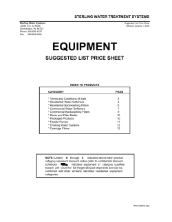
FIGURE 1-1 - COMPRESSION
COMPRESSOR - The Gardner-Denver” Rotary Screw
compressor is a single stage, positive displacement
rotary machine using meshing helical rotors to effect
compression. Both rotors are supported between high
capacity roller bearings located outside the compression chamber. Single width cylindrical roller bearings are
used at the inlet end of the rotors to carry part of the
radial loads. Tapered roller bearings at the discharge
end locate each rotor axially and carry all thrust loads
and the remainder of the radial loads.
COMPRESSION
PRINCIPLE (Figure l-l) - Compression is accomplished by the main and secondary rotors
synchronously meshing in a one-piece cylinder. The
main rotor has four (4) helical lobes 90В° apart. The
secondary rotor has six (6) matching helical grooves 60В°
apart to allow meshing with main rotor lobes.
The air inlet port is located on top of the compressor
cylinder near the drive shaft end. The discharge port is
near the bottom at the opposite end of the compressor
cylinder. Figure 1-1 is an inverted view to show inlet and
discharge ports. The compression cycle begins as rotors unmesh at the inlet port and air is drawn into the
cavity between the main rotor lobes and secondary rotor
grooves (A). When the rotors pass the inlet port cutoff,
air is trapped in the interlobe cavity and flows axially with
the meshing rotors (B). As meshing continues, more of
the main rotor lobe enters the secondary rotor grove,
normal volume is reduced and pressure increases.
Oil is injected into the cylinder to remove the heat of
13-9/10-641
CYCLE
compression and seal internal clearances. Volume reduction and pressure increase continues until the air/oil
mixture trapped in the interlobe cavity by the rotors
passes the discharge port and is released to the oil
reservoir (C). Each rotor cavity follows the same “fillcompress-discharge” cycle in rapid succession to produce a discharge airflow that is continuous, smooth and
shock free.
AIR FLOW IN THE COMPRESSOR SYSTEM (Figure
5-1, page2, Section 5) -Air enters theairfilterand passes
through the inlet unloader valve to the compressor. After
compression, the air/oil mixture passes into the oil reservoir where most of the entrained oil is removed by
velocity change and impingement and drops back into
the reservoir. The air and remaining oil passes into the
separator and separator housing where the oil is separated and passes through tubing connecting the separator housing and compressor. The air passes through
the minimum pressure valve, discharge check valve
and cooler, then to the plant air lines.
LUBRICATION,
COOLING AND SEALING - Oil is
forced by air pressure from the oil reservoir through the
oil cooler, thermostatic mixing valve, and oil filter and
discharges into the compressor main oil gallery. A portion of the oil is directed through internal passages to
the bearings, gears and shaft oil seal. The balance of the
oil is injected directly into the compression chamber to
remove heat of compression, seal internal clearances
and lubricate the rotors.
Section 1
Page 1
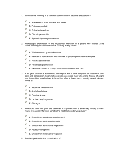
INSTRUMENT
WINDOW
DISPLAY
f
I
/
-EMERGENCY
STOP
ad
=
STARTER
CONTROL
BOX
EMERGENCY
STOP
7
AUTO SENTRY ES
CONTROL
PANEL
CONTROL
\
TRANSFORMER=
.
o
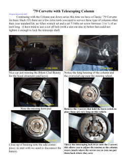
FIGURE 1-2 - STARTER BOX
a
—MAIN
MOTOR
STARTER
�FAN
MOTOR
STARTER
.
o
FIGURE1-3
DRIVE
AIR
MOTOR
FILTER
.–--–.-y-.~.--– 1
FIGURE 1-4-
- PACXAGE -CONTROLLER&STARTERS
1
COOLING
\
jr
PACKAGE - DRIVE MOTOR & AIR FILTER
13-9/1 0-641
Section 1
Page 2
FAN
SAFETY PRECAUTIONS
Safety is everybody’s business and is based on your use of good common sense. All situations or circumstances
cannot always be predicted and covered by established rules. Therefore, use your past experience, watch out for
safety hazards and be cautious.
Some general safety precautions are given below:
~DANGER
Failure to observe these notices could result in injury to or death of personnel.
.Keep
fingers and clothing a way from revolving fan, drive coupling, etc.
. Do not use the air discharge
human consumption.
в—Џ
from this unit for breathing
- not suitable for
Do not loosen or remove the oil filler plug, drain plugs, covers, the thermostatic
mixing valve or break any connections, etc. in the compressor air or oil system
until the unit is shut down and the air pressure has been relieved.
. Electrical shock can and may be fatal.
в—Џ
Compressor unit must be arounded in accordance with the National Electrical
Code. Aground jumper equal in size to the equipment ground conductor must
be used to connect the compressor motor base to the unit base.
в—Џ
Fan motors and must remain arounded to the main base through the starter
mounting panel in accordance with the National Electrical Code.
. Open main disconnect
в—Џ
switch and lockout before working on the control.
Disco nnect the compresso r unit from its power source, tag and lockout before
working on the unit - this machine is automatically controlled and may start at
any time.
13-9/10-641
Section 1
page 4
~WARNING
Failure to observe these notices could result in damage to equipment.
в—Џ
Stopunit
the if any repairs or adjustments
required.
on or around the compressor
are
. Disconnect the compressor unit from its power source, tag and lockout before
working on the unit - this machine is automatically controlled and may start at
any time.
. An Excess Flow Valve should be on all compressed air supply hoses exceeding 1/2 inch inside diameter. (OSHA Regulationj Section 1518.302)
. Do not exceed the rated maximum pressure values shown on the nameplate.
в—Џ
Do not ope rate unit if safety devices are not operating
periodically. Never bypass safety devices.
13-9/10-641
Section 1
Page 5
properly.
Check
DECALS
@
DiSCHARGE AIR USED FOR
BREATHING WILL CAUSE
SEVEREINJURY OR DEATH.
CONSULT FILTRATION
AIR AND OIL UNDER PRESSURE
WILL CAUSE SEVEREPERSONAL
INJURY OR OEATH.
SHUTDOWNCOMPRESSORAND
RELIEVE SYSTEM OF ALL
PRESSURE BEFORE REMOVING
VALVES, CAPS, PLUGS,
SPECIALIST FOR
ADDITIONALFILTRATION
AND TREATMENTEQUIPMENT
TO MEET HEALTH AND
SAFETY REGULATIONS.
—
FITTINGS, BOLTS, AND FILTERS.
—
212EAQ077
208 EAQ077
HIGH vOLTAGE.
ROTATING MACHINERY.
AIR AND 0IL
UNDERPRESSURE.
IMPROPERMODIFICATION
OF EQUIPMENTWILL
CAUSE SEVERE PERSONAL
INJURY OR DEATH.
DO NOT MODIFY
UNIT WITHOUT
WRITTEN PERMISSION
FROM MANUFACTURER.
218EAQ077
o.
0
%
0
UNIT CANAUTOMATICALLY
MACHINERYCAN
CAUSE INJURY OR DEATH.
KEEP ALL GUARDSAND
SAFETY DEVICES IN
PLACE.
ROTATING
RESTART.
CAN CAUSE PERSONAL INJURY
OR DEATH.
KNOW MODE OF OPERATION
BEFORE WORKING ON OR
NEAR THE MACHINE.
—
207 EAQ077
211 EAQ077
13-9/10-641
Section 1
Page 6
ELECTRICAL SHOCK FROM
IMPROPER GROUNDING CAN
CAUSE INJURY OR DEATH.
GROUND UNIT AND RELATED
EQUIPMENT ACCORDINGTO
NATIONAL ELECTRIC CODE
AND LOCAL REGULATIONS.
—
216EAQ077
ELECTRICAL SHOCKCAN
CAUSE INJURY OR DEATH.
DISCONNECTALL CIRCUITS
BEFORE WORKING ON T HIS
CONTROL.
SEE WIRING DIAGRAM.
AIR AND OIL UNDER
PRESSURE.
CAN CAUSE SEVERE
PERSONAL INWRY
OR OEATH.
INSPECT OIL RESERVOIR
FOR CRACKS AT LEAST
ANNUALLY.
—
—
I
217EAQ077
@
ELECTRICAL ARCING CAN
CAUSEA FIRE WHENUNIT IS
MOUNTEDON A COMBUSTIBLE
SURFACE RESULTING IN
PERSONAL INJURY OR
PROPERTY DAMAGE.
UNIT MUST BE MOUNTEDON
A FLOOR PLATE EXTENDING
ON ALL SIDES.
SEE INSTALLATION
DRAWINGFOR PROPER
DIMENSIONS.
MACHINE
DAMAGEOR INJURY
CAN OCCUR DUETO IMPROPER
LIFTING.
D0 NOT LIFT MACHINEWITH
THE MOTOR EYEBOLT.
—1
I
—
221 EAQ077
206EAQ077
13-9/10-641
Section 1
Page 7
SECTION 2
INSTALLATION
GENERAL - On receipt of the unit, check for any damage that may have occurred during transit or handling.
Report any damage or missing parts as soon as possible.
~cAuTlON
Do not electric weld on the compressor
or base; bearings can be damaged by
passage of current.
LIFTING UNIT - Proper lifting and/or transporting methods must be used to prevent damage.
I
from the compressor operating area. Atypical inlet-outlet air flow arrangement is shown in Figure 2-1.
AIR-COOLED UNIT - A combination oil/aftercooler is
supplied as standard equipment on all air-cooled units.
The air-cooled unit with the standard enclosure requires
sufficient flow, Figure 2-2, for the compressor
oil/aftercooling system and for electric motor cooling.
Air is drawn into the unit at the motor side of the enclosure and is exhausted at the oil cooler side. Do not block
the air flow to and from the unit. Allow three and one-half
(3-1/2) feet to the nearest obstruction on the starter end
and control box end of the unit. Allow three (3) feet to
the nearest obstruction above and on other sides of unit.
For continuous efficiency, oil cooler cores must be periodically cleaned with either vacuum or compressed air.
I
~CAUTION
~wARNING
Lift compressor unit by base only. Do
not use other places such as enclosure, motor, compressor oil discharge
manifold and piping as lifting points.
r
t
~DANGER
The eyebolts or lugs provided on the
motor are for lifting the motor only and
should not be used to lift any additional
weight. All eyebolts must be securely
tightened. When lifting the motor the
lifting angle must not exceed 15 degrees. failure to observe this warning
may result in damage to equipment or
personal injury.
For aluminum oil coolers, do not use
any cleaning solution that is not compatible with aluminum. Use of improper
solution
may result in damage
to
cooler.
EXHAUST
LOUVEREO
FAN
LOUVERED
WINDOW
Wlfioow
.*L~:,,,,,!..
i.
bY
I
-
11
., :.,
1
~ >
LJ
..
AIR OUT
AIR
AIR
IN
lN
*
~’
I
.
$
k
.
I
UNIT
1
�
�
Lifting slots are provided in the base for towmotor use.
Unit fray also be moved into location by rolling on bars.
A75179
LOCATION - The compressor should be installed,
whenever possible, in a clean, well-lighted, well-ventilated area with ample space all around for maintenance.
Select a location that provides a cool, clean, dry source
of air. In some cases it may be necessary to install the
air filter at some distance from the compressor to obtain
proper air supply.
Both the air-cooled and water-cooled units require cooling air as well as air to the compressor inlet. Proper
ventilation MUST be provided; hot air must be exhausted
13-9/1 0-641
-
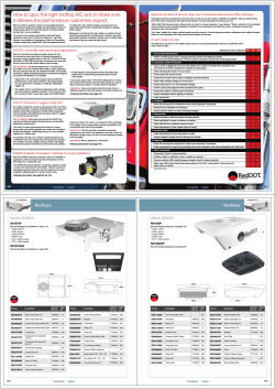
FIGURE 2-1 - TVPICAL COMPRESSOR
ROOM
Minimum Air Flow* For Compression
And cooling (Cubic Feet/Minute)
HP
Air Cooled
Water Cooled
40& 50
6,500
1,400
60,75, 100
12,500
1,700
* 80”F inlet air
Section 2
FIGURE 2-2
Page 1
I
COMPRESSOR
MOTOR
8 FT.
PLYWOOD
fENCE-
8
FT.
PLYWOOD
“FENCE”
\/r
\/
WELL MAN
RADIANT
2-CLEMENT
HEATER
(OR EOUAL)
RH400
WI TH (2) RH4502
ELEMENTS
- 2 REO”D.
3.200
WATTS
EACH
4 ET.
7
pb
�._
/
/
/
L RESERVOIR
\’
�/
\
HEATER
(OR
RH7000
WITH
ELEMENTS
6200
WATTS
DIANT
2-ELEMENT
EOUAL)
(2) RH7502
Z REOD
EACH
FIGURE 2-3 - COLD WEATHER
ELEVATION
FOUNDATION
- The G-D Rotary Screw compressor
requires no special foundation, but should be mounted
on a smooth, solid surface. Whenever possible installthe
unit near level. Temporary installation may be made at
a maximum 10В° angle lengthwise or 10В° sidewise.
Mounting bolts are not normally required. However,
installation conditions such as piping rigidity, angle of
tilt, or danger of shifting from outside vibration or moving
vehicles may require the use of mounting bolts and
shims to provide uniform support for the base.
OIL RESERVOIR DRAIN - The oil drain is piped from
the bottom of the reservoir to the side of the frame. This
drain is approximately 4.50 inches above the floor level.
If this is not sufficient to conveniently drain the oil some
other methods of providing drain are:
1.
Elevate the compressor unit on raised blocks to
obtain the desired drain height.
13-9/1 0-641
VIEW
INSTALLATION
If wet cleaning is required, shield motor and spray on a
mild soap solution and flush with clean water.
WATER-COOLED
UNITS - The water-cooled unit with
the standard enclosure requires sufficient airflow, Figure
2-2, previous page, for electric motor cooling. Air is
drawn into the unit at the top of the enclosure and is
exhausted at the motor side. Do not block airflow to and
from unit. Allow three and one-half (3-1/2) feet to the
nearest obstruction on the starter end and control box
side of the unit. Allow three (8) feet to the nearest
obstruction above and on other sides of the unit.
/
~CAUTION
If the compressor unit base is raised
above floor level, the space between
the floor and the base bottom must be
closed with solid material all around to
prevent recirculation of hot air from the
oil cooler end and over temperature
operation.
2.
Construct an oil sump or trough below the floor
level and pump or bail the drained oil.
3.
Pump oil from the reservoir filler opening or drain
to a container.
ENCLOSURE - The compressor, electric motor, oil
cooler and aftercooler are mounted inside the enclosure.
Service doors are provided for maintenance access. Be
sure to allow enough space around the unit for the doors
to open completely.
Any of the enclosure doors maybe removed by opening
the door and lifting it up slightly to disengage the hinges.
The motor inspection/air filter service panel is held by
two latches and lifts away from the enclosure. The air
outlet panel is attached by screws to the enclosure and
is not readily removable.
INSTALLATION FOR COLD WEATHER OPERATION
- Itis recommended that whenever possible the unit be
installed inside a shelter that will be heated to tempera-
Section 2
Page 2
above
freezing
(32”F, O“C). This will eliminate
many of the problems associated with operating the
units outside in cold climates where freezing rain, drifting
snow, freezing condensate and bitter cold temperatures
are encountered.
tures
2.
Auto operation should not be used in extreme
environments.
3.
Some means of providing heat during shutdown
should be provided. There are various methods to
accomplish this, but since openings are not provided for sump heaters, the use of radiant heaters
is recommended. The heaters should be sized to
provide at least a + 10В°F environment for coolers,
motor and sump.
Figure 2-3, previous page,
shows how these might be located in a typical
installation and sizes required.
Refer to Engineering Data Sheet 13-9-411 for the advantages of using the heat recovered from rotary compressors. This heat recovery could easily pay for an adequate
shelter for the unit.
When an outside installation must be made, the precautions required will depend on how severe the environment. The following are general guidelines for outside
installations:
Cold Weather (Down To + 10”F)
1.
Be sure all control lines, drains and traps are heated
to avoid freezing of condensate. Heat tape with
thermostat control is generally satisfactory for this
purpose and can be obtained at various local
plumbing or hardware outlets at nominal cost.
2.
If an air-cooled aftercooler is to be used, provisions
to bypass the aftercooler should be made. Since
cold air contains very little moisture, successful
operation can be achieved without the aftercooler.
3.
Provide at least some simple shelter such as a
plywood windbreak to protect against drifting
snow.
4.
Use only Gardner-Denver@ AEON �M 9000 lubricant.
5.
Monitor unit carefully during start-up and operation
to be sure it is functioning normally.
6.
Specify NEMA 4 enclosure for electrical devices.
Extreme Cold Weather Operation
(Down To -40”F)
In addition to the above, the following should be provided:
1.
It will probably be necessary to provide shutters or
to block off part of the cooler in some manner since
the cooler is greatly oversized for operation in these
low temperatures. Since shutters are not provided
as a factory option, blocking off a portion of the
cooler with plywood should be satisfactory.
Remember unsheltered (outside) installations should be
avoided where possible. Installation next to a heated
building where enough heat can be used to keep the
compressor room above freezing will save many complications in the operation and installation of the unit.
Refer to Engineering Data Sheet 13-9-411 for the advantages of using the heat recovered from rotary compressors. This heat recovery could easily pay for an
adequate shelter for the unit.
AUXILIARY AIR RECEIVER - An auxiliary air receiver is
not required if the piping system is large and provides
sufficient storage capacity to prevent rapid cycling.
When used, an air receiver should be of adequate size,
provided with a relief valve of proper setting, a pressure
gauge and a means of draining condensate.
MOISTURE
SEPARATOR/TRAP
- Since
unit is
equipped with a built-in aftercooler, a combination moisture separator and trap is furnished with the unit.
CONTROL PIPING - External control piping is not necessary since the unit is factory wired and piped for the
control system specified.
INLET LINE - Where an inlet line is used between the air
filter and the compressor, it must be thoroughly cleaned
on the inside to prevent dirt or scale from entering the
compressor. If welded construction is used, the line
must be shot blasted and cleaned to remove welding
scale. In either case, the inlet line must be coated
internally by galvanizing or painting with a moisture and
oil-proof sealing lacquer. Up to ten (10) feet in length,
the inlet line should be the full size of the inlet opening
on the compressor. If an extra-long line is necessary,
the pipe size should be increased according to Inlet Line
Chart below.
INLET LINE LENGTHS
Length of Inlet Line
Diameter of Pipe Size
Oto 10 Feet .......................................................................................................... Same as Compressor Inlet Opening
10to 17 Feet .......................................................................................................... One Size Larger Than Inlet Opening
17t038 Feet .........................................................................................................Two Sizes Larger Than Inlet Opening
13-9/1 0-641
Section 2
Page 3
HEAT EXCHANGER
Water Temperature To Heat Exchanger
60”F
70”F
80”F
90”F
Max Water
Flow (GPM)
Approx. Water Press. Dro
@ 90В°F Water Temp. (PSI)
EBHSHA
EBHSHC
3.4
3.4
4.3
4.3
5.7
5.7
8.6
8.6
30.0
30.0
1.0
1.0
50 HP
50 HP
EBHSJA
EBHSJC
4.1
4.1
5.1
5.1
6.8
6.8
10.2
10.2
30.0
30.0
1.5
1.5
60 HP
60 HP
EBMSKA
EBMSKC
5.0
5.0
6.2
6.2
8.3
8.3
12.5
12.5
40.8
40.8
2.0
2.0
75 HP
75 HP
EBMSLA
EBMSLC
6.0
6.0
7.6
7.6
10.1
10.1
15.1
17.1
40.8
40.8
1.5
1.5
100 HP
100 HP
100 HP
EBPSMA
EBPSMC
EAPSMD
8.4
8.4
8.4
10.5
10.5
10.5
14.1
14.1
14.1
21.1
21.1
21.1
40.8
40.8
40.8
5.0
5.0
5.0
Approx. Water Press. Drop
@ 90F Water Temp. (PSI)
HP
Model
40 HP
40 HP
AFTERCOOLER
Water Temperature To Heat Exchanger
60”F
70”F
80В°F
90”F
Max Water
Flow (GPM)
EBHSHA
EBHSHC
.5
.5
.7
.7
.9
.9
1.3
1.3
26.0
26.0
50 HP
50 HP
EBHSJA
EBHSJC
.7
.7
.9
.9
1.2
1.2
1.8
1.8
26.0
26.0
Less than 1 PSI for
60 HP
60 HP
EBMSKA
EBMSKC
.8
.8
1.0
1.0
1.4
1.4
2.1
2.1
26.0
26.0
any flow rate shown
75 HP
75 HP
EBMSLA
EBMSLC
1.2
1.2
1.5
1.5
2.0
2.0
3.0
3.0
26.0
26.0
2.1
2.1
2.1
2.8
2.8
2.8
4.1
4.1
4.1
26.0
26.0
26.0
HP
Model
40 HP
40 HP
100 HP
100 HP
100 HP
EBPSMA
EBPSMC
EAPSMD
1.7
1.7
1.7
FIGURE 2-4-
HEAT EXCHANGER
APPROXIMATE
in the
table.
(OIL COOLER-AFTERCOOLER)
WATER FLOW - U.S. GALLONS/MINUTE
Accessibility for inlet air filter servicing must be considered when relocating the filters from the unit to a remote
location.
~DANGER
Discharge air used for breathing
cause severe injury or death.
DISCHARGE SERVICE LINE - The discharge service
line connection on both water-cooled and air-cooled
units is made at the right hand corner of the unit, viewed
from the opposite end from control panel side. When
manifolding two or more rotary screw units on the same
line, each unit is isolated by the check valve in the unit
discharge line. If a rotary screw unit is manifolded to
another compressor, be sure the other compressor has
a check valve in the line between the machine and the
manifold. If a rotary screw and a reciprocating compressor are manifolded together, an air receiver must be
located between the two units.
13-9/10-641
will
Consult filtration specialists for additional filtration and treatment equipment to meet health
and safety
standards.
BLOWDOWN VALVE PIPING - The blowdown valve is
fitted with a muffler for operation indoors. If the installation requires, the muffler may be removed and the blowdown valve piped to the outside with a pipe size the same
as the blowdown valve outlet connection.
Section 2
Page 4
C76683
\ THERMOSTATIC
MIXINGVALVE
---—
---—-~-
______
* WATER
_
~NTROL
V/UVL�“”
““’
,
VALVE
A
HEAT EXCHANGER
OUT
1
I
~~.~J*~ L“’’?JER
*.ATER
AFTER COOLER
WATER
IN
<,,,
C76682
yq::::”~=
AIR
IN
SEPARATOR / TRAP
*
(OPTIONAL) WATER CONTROL VALVE AND WATER SHUTOFF VALVE MUST BE ORDERED SEPARATELY.
FIGURE 2-6-
FIGURE 2-5 - SERIES PIPING
WATER PIPING (Water-Cooled
Heat Exchanger
Models Only) - On machines equipped with watercooled heat exchangers, the water inlet and outlet connections are located in the unit base flange on the left
side of the unit.
The water source should be capable of supplying up to
the maximum flow shown in Figure 2-4, previous page,
at a minimum pressure of 40 psig; maximum allowable
water pressure is 150 psig. The water flow rates shown
in Figure 2-4, previous page, are approximate and a
guide to sizing piping, cooling tower and other water
system equipment.
The heat exchanger system is designed to operate with
water inlet temperatures from 60”F to 90”F and a water
outlet temperature not to exceed 11O“F. If water cooler
than 60В°F is used, high water outlet temperatures (over
110”F) will be experienced along with shottened heat
exchanger life caused by tube fouling and corrosion. If
water warmer than 90”F is used, higher compressor oil
inlet temperatures and high water usage will result.
Most water systems will require control of impurities:
filtration, softening or other treatment. See “Compressor Oil Cooler - Water-Cooled Heat Exchanger” for more
information on the water system.
SERIES PIPING (Figure 2-5) - Water flow must be
through aftercooler first for effective cooling of discharge air and is so piped on the standard water-cooled
unit.
PARALLEL PIPING (Figure 2-6) - A separate water
control valve is required to control the discharge air
temperature. If a remote (externally mounted) water-
13-9/10-641
cooled
aftercooler
exchanger,
PARALLEL PIPING
is piped
provide
in parallel
a separate
the aftercooler
and pipe separate
the aftercooler
and
The water
out
control
of the
range
heat
heat
valve
long as a minimum
with
the
control
heat
valve
inlet waterlines
for
to both
exchanger.
is to be adjusted
exchanger
regardless
water
within
of inlet water
flow
flow for a given
the
to maintain
140В°
to
150В°
or temperature
temperature
oil
F.
as
is met
5 for
adjustment instructions and maximum allowable lubricant temperature.
(Figure
2-4,
page
4, this
section).
See
Section
ELECTRICAL WIRING - Standard Units - The ElectraSaver” compressor is factory wired for all starter to
motor and control connections for the voltage specified
on the order. It is necessary only to connect the unit
starter to the correct power supply. The standard unit is
supplied with an open drip-proof motor, a NEMA 12
starter and control enclosure. See “Location” paragraph
for distance to nearest obstruction on starter and control
box sides of the unit.
Lower operating voltages (200/208) require that the unit
starter be remote mounted since the starter is too large
to be mounted within the control enclosure. If not supplied with the compressor unit, the starter is to be a size
6 full voltage non-reversing type in NEMA (CEMA) enclosure suitable for the environment, with two (2) rejection type control circuit fuses (size according to motor
starter manufacturer’s standard), a 200 (208) volt coil,
and three (3) overload heaters for 200 (208) volt 100 HP,
1.15 service factor motor. The overload heaters are to
be selected according to starter manufacturer’s tables
based on motor nameplate full load amperage.
Section 2
Page 5
I
A
!
1.
Stop the unit.
2.
Disconnect the unit, tag and lockout from the
power supply.
3.
Remove the relief plug and free hole of hardened
grease.
4.
Wipe lubrication fitting clean and add grease with
a hand-operated grease gun.
5.
Leave the relief plug temporarily off. Reconnect
unit and run for about 20 minutes to expell the
excess grease.
6.
Stop the unit. Replace the relief plug.
7.
Restart the unit.
WARNING
Electrical shock can cause injury or
death. Open main disconnect switch
before working on starter/control box.
GROUNDING - Equipment
must
be grounded
in accor
dance with Table 250-95 of the National Electrical Code
~wARNING
Failure to properly ground the compressor package could result in controller malfunction.
MOTOR LUBRICATION - Long time satisfactory operation of an electric motor depends in large measure on
proper lubrication of the bearings. The charts on the
next page show recommended grease qualities and
regressing intervals for ball bearing motors. For additional information, refer to the motor manufacturer’s
instructions. The following procedure should be used in
regressing:
ELECTRIC
I
~WARNING
Rotating machinery can cause injury or
death. Open main disconnect, tag and
lockout before working on electric
motor.
MOTOR GREASE RECOMMENDATIONS
Standard
Service
High
Temperature
Worked Penetration ..........................................................................
265-296
220-240
Viscosity, SSU At 1000F.....................................................................
400-550
475-525
Soap Type .........................................................................................
Lithium
Lithium
N-H Bomb, Minimum Hours For 20 PSI Drop at 21 O”F....................
750
1000
Bleeding, Maximum Weight % In 500 Hours 212”F. ..... ...................
10
3
Rust inhibiting ....................................................................................
Yes
Yes
ELECTRIC
MOTOR REGREASING
INTERVAL
Typical Examples
Rating
One- or Two-Shift Operation
150 HP & Below
18 Months
Severe
Continuous Operation
150 HP & Below
9 Months
Very Severe
Dirty Locations, High
Ambient Temperature
150 HP & Below
4 Months
Type of Service
Standard
13-9/10-641
Section 2
Page 6
Relubrication Interval
SECTION 3
STARTING & OPERATING
PROCEDURES
PRESTART-UP
INSTRUCTIONS
- A new unit as rehas been prepared for shipping
only. Do not attempt to operate the unit until checked
and serviced as follows:
ceived
1.
from
2.
Air Filter and
the factory
Filter,”
fill, or filling
after
a complete
draining
show
the
oil level
air filter
complete
Refer
servicing
to be sure
to
Section
instructions.
it is clean
6,
Be
“Air
sure
Coupling - Check all bolts and cap screws for
tightness. See Section 7.
4.
Piping - Refer to Section 2, “installation,” and make
sure piping meets all recommendations.
5.
Electrical - Check the wiring diagrams furnished
with the unit to be sure it is properly wired. See
Section 4, “Controls and Instruments,” for general
wiring diagrams and Section 2 for installation instructions.
6.
Groundina - Equipment must be arounded in accordance with Table 250-95 of the National Electrical Code.
of the
“EXCESS OIL” range. After start-up, the oil will fall into
the green operating range as system components
are filled. if necessary, add oil to bring the level to
the top of the green range as read when the unit is
operating at full load and normal pressure. See
Figure 5-4, page 4, Section 5.
may
the
assembled.
3.
REPLACE OIL FILTER EVERY 1000 HOURS.
Initial
for
Inspect
the inlet line, if used, is tight and clean.
Compressor Oil - Check oil level in the reservoir.
Add oil only if the oil level gauge reads in the red
“ADD OIL’ range. Do not mix different type oils.
Unit is shipped filled with Gardner-Denver”
AEON �M9000 Lubricating Coolant which is suitable
for the first 8000 hours under normal operating
conditions.
system,
tightly
in the yellow
~WARNING
I
NOTICE
Regular maintenance and replacement
at required intervals of the oil filter, air
filter and air-oil separator is necessary
to achieve maximum service and extended drain intervals of AEON 9000
synthetic lubricant. Use only genuine
Gardner-Denver
filters designed and
specified for this compressor.
Failure to properly ground the compressor package could result in con~
7.
Rotation - Check for correct motor rotation using
“JOG MODE.” Compressor drive shaft rotation
must be clockwise standing facing the compressor
sheave.
~wARNING
I
~DANGER
Operation with incorrect motor rotation
can damage equipment and cause oil
eruption from the compressor
inlet.
When checking motor rotation, induce
minimum rotation (less than one revolution if possible). Never allow motor to
reach full speed.
Always stop the unit and release air
pressure
before removing oil filler
plug. Failure to release pressure may
result in personal injury or death.
During unloaded operation and after shutdown, the
system will partially drain back into the oil reservoir
and the oil level may read higher than when operating on load. DO NOT DRAIN OIL TO CORRECT;
on the next loaded cycle or start, oil will again fill
the system and the gauge will indicate the operating level.
13-9/10-641
8.
Section 3
System Pressure - Set the controls to the desired
unload pressure and differential. DO NOT EXCEED
MAXIMUM OPERATING PRESSURE ON COMPRESSOR NAMEPLATE. See Section 4, “Controls
and Instruments,” for procedure.
Page 1
I
~wARNING
Operation at excessive discharge air
pressure can cause personal injury or
damage to equipment.
Do not adjust
the full discharge air pressure above
the maximum stamped on the unit
nameplate.
9.
Operating Mode - Refer to Section 4 for detailed
information on the control system.
10.
Enclosure - Check for damaged panels or doors.
Check all screws and latches for tightness. Be sure
doors are closed and latched.
STARTING THE UNIT- OBSERVE UNIT COLD OR HOT
STARTING PROCEDURES
Unit Cold - If the unit is a water-cooled heat exchanger
model, open any manual water inlet valves wide open.
Start the unit by pushing either the “CONSTANT RUN”
button or one of the “AUTO” buttons. Since the unit is
equipped with a minimum (65 psig) pressure discharge
valve, no special procedure to maintain unit reservoir
pressure is required.
Unit Hot - No warm-up period is required. If the unit is a
water-cooled heat exchanger model, open any manual
water inlet valves wide open. Start the unit by pushing
either the “CONSTANT RUN” button or one of the
“AUTO” buttons.
DAILY CHECK
Schedule.”
- Refer to Section 8, “Maintenance
STOPPING THE UNIT - Press “STOP-RESET” button.
The oil reservoir will automatically blow down as the
motor stops. If the unit is a water-cooled heat exchanger
type, close any manual water inlet valves.
SEQUENCING COMPRESSORS
Sequencing compressors with the AUTO SENTRY-ES
controller is as simple as plugging in a telephone to a
wall jack. The only item required to make the system
functional is a standard telephone cable identical to
cables that connect nearly every telephone to its wall
jack. One less cable than the number of compressors to
be sequenced is required. For example, to sequence
four compressors, three cables are required. A kit,
200 EAP752, is available which contains all material
needed to sequence up to five compressors. This kit
contains 500 feet of cable, eight modular connectors and
a crimping tool to install the connectors.
In spite of the fact that it is a standard feature, and its
inherent installation simplicity, the sequencing function
of a multi-compressor “AUTO SENTRY-ES” system is
the most fully-featured, functionally-complete available
today.
1.
INSTALLATION
A proper sequencing installation requires two or more
Gardner-Denver rotary air compressors complete with
“AUTO SENTRY-ES” controllers, piped into a common
air system, interconnected as described above. All standard practices common to sound air compressor installations such as proper sizing of discharge piping, proper
13-9/1 0-641
electrical supply and conductor sizing, and grounding
are to be observed. The serial communications interface
meets RS-485 standards, the most widely used interface
in harsh, industrial environments today. However it is still
recommended that the communications cables be
routed through metallic conduit to provide them with
both mechanical protection and electromagnetic shielding.
Each control circuit board has two modular jacks which
accept standard RJ-12 telephone plugs. One jack is
vacant; the other has a short pigtail plugged into it. To
interconnect two compressors, plug the cable into the
vacant jack on each controller. For installations of more
than two units, the pigtail plug must be disconnected on
all controllers except the two at each end of the communications line. The order of interconnection has no effect
on the system operation. The following conditions are
necessary and sufficient for proper operation:
1.
Every compressor must have a cable connecting it to another compressor. One less cable
than the number of units sequenced, must be
used.
2.
Each board that has only one cable connected
to it must have its pigtail plugged into the
unused jack. All installations will have two such
units.
Section 3
Page 2
Il.
OPERATION
A.
ESTABLISHING THE INITIAL SEQUENCE
Operation of compressors in sequence requires only a
press of the �sequence’ key on each compressor in the
system. Since the sequencing algorithm includes provisions for automatic replacementof a failed master or �lead’
compressor, it is important for the operator to be aware
of the hierarchy of events when starting the system.
The first compressor placed in sequence mode will become the master. However, since any compressor first
placed in sequence has no way of knowing whether or
not a master exists, it will first assume the highest rotation
number available. For example if the number of units to
be sequenced is programmed at four, any compressor
will start out in position four when placed in sequence
mode. It will then listen on the communications line for a
call from the master.
If no call is received, it will assume position three and
again wait for a call from the master. After another lack
of master call, it assumes position two. Subsequently, it
assumes position one which makes it the master. As
soon as a master is established, it immediately attempts
to call all other units and assigns them successive rotation positions. The system is now active.
Before a master is established, the system is not deprived
of air. This is due to one of the outstanding features of
the “AUTO SENTRY-ES” sequencing system: pressure
control is always executed locally at each individual
compressor. The effective setpoint for compressor control is the programmed setpoint minus 3(rotation number
1). So whiie a compressor (or compressors) is/are
counting down towards establishing a master, they are
also capable of delivering air at a pressure determined
by the above formula.
To insure that two or more machines do not simultaneously decrement their rotation numbers and simultaneously become masters, it is advisable to p!ace the
desired master in sequence mode first and wait until the
first decrement in rotation number is seen (about 7 seconds) before placing subsequent compressors in sequence mode. If it is desired to dictate the complete initial
sequence manually, wait until the previous machine decrements one position and then place the next desired
compressor in sequence mode. If it is acceptable to let
the master determine the initial sequence, simply wait
until the master has decremented its rotation number
once, and then place all remaining compressors in sequence mode. Remember that once a master is established, no further self-decrementing is done by the
individual compressors. Instead, they will wait until the
master assigns them a rotation number.
13-9/10-641
Rotation numbers are displayed in the bottom display
line, with the mode indication. For example, the mode
indication for the current master is SEQI; for the first lag
compressor, SEQ2; second lag SEQ3,etc.
B.
HOW THE “AUTO SENTRY-ES”
PRESSURE WHILE SEQUENCING
CONTROLS
Each compressor operates exactly the same as if it were
in AUTO mode with one exception: it has a dynamic
setpoint. The initial setpoint is determined by the equation shown above. A compressor is started when the
system pressure drops below its programmed reset
point, after waiting for [’LAG START INTERVAL’ times
(rotation number - 1)] seconds. This prevents all lag
compressors
from starting at once. Note that a
compressor’s [’LAG START INTERVAL’ times (rotation
number 1)1timer is not reset to zero until that compressor
is started. This means that the time for the next lag
compressor to come on is aiways somewhat less than
�LAG START INTERVAL’.
EXAMPLE:
In a three compressor sequence system, SET PRESSURE = 100 PSI; RESET PRESSURE = 90 PSI; LAG
START INTERVAL = 15 seconds. The lead compressor
is running alone, maintaining 100 PSI by modulation
when an air tool is brought on line causing the air demand
to exceed the capacity of the lead compressor. When the
pressure drops to 90 PSI, the #2 unit times out its 15
second timer and starts. It takes 5 additional seconds for
the pressure to rise above 90 PSI. The #3 unit whose
timer was initialiy set at 30 seconds (15 x [3 - 1]), has
counted down 20 seconds (the total time that system
pressure was below 90 PSI). If air demand increases
again, the pressure will have to fall below 90 PSI for only
10 seconds more to start unit #3.
As was previously stated, a lag compressor’s modulation
setpoint (PSET for short) is [SET PRESSURE - 3(rotation
number - 1)]. Thus in the above example, the first lag
compressor (rotation #2) has a PSET of 97 PSI; the
second lag, 94 PSI, and so on. But look what happens in
an eight compressor installation: The eighth compressor
will have an initial setpoint of [100 - 3(8 - 1)], or 79 PSI.
Does this mean that an eight compressor installation
must operate 21 PSI below the desired operating point
when all compressors are running? NO! This iswhere the
“AUTO SENTRY-ES” dynamic setpoint controi takes
over. This is how it works: Whenever the system pressure is below the programmed RESET PRESSURE, the
PSET of each lag compressor is incremented 1 PSI every
thirty seconds. Thus, after a short interval (about five
minutes in this example), the PSET of the last sequenced
compressor will ciimb up until either it equals the RESET
PRESSURE, or a decrease in demand causes the actual
Section 3
Page 3
system pressure to rise above the RESET PRESSURE.
It can be seen then, that except for short periods just
after a sudden increase in demand, the “AUTO SENTRYES”, with its dynamic setpoint control, will maintain system pressure between the limits of RESET PRESSURE
and SET PRESSURE. Remember, RESET and SET
PRESSURE values are programmed by the operator so
the operating range is completely programmable and
predictable.
Dynamic
setpoint control will also work in reverse of the
operation described above. Obviously, incrementing
setpoints will cause overlap of the compressors’ modulation ranges. While this enables us to maintain a higher
pressure than competitor’s sequencers, overlap is undesirable as demand decreases, because a system could
end up with several compressors running partially
loaded instead of running the minimum number of fully
loaded compressors. To overcome this, as pressure
rises through the range between RESET and SET, the
lag compressors’ PSET’S are now decremented, reversing the effect described above during periods of high
demand. - The “AUTO SENTRY-ES’ keeps track of all
functions at all times so there is never any mix-up of
setpoints and the proper rotation sequence is always
maintained.
ill.
THE AUTOMATIC
SEQUENCE
CHANGE
After the master (lead) compressor has served for the
duration programmed (TRANSFER INTERVAL), it relinquishes control and assigns itself the highest available
rotation number. The lag compressors detect the loss of
the master and decrement their rotation numbers. Number 2 becomes number 1, the new master, number 3
becomes number 2, etc.
It should be noted also that whenever the master detects
a missing rotation number, such as when a compressor
is turned off that was previously in the rotation, it will
automatically �close the gap’ by decrementing the rotation numbers of all compressors whose rotation numbers were greater than the missing number. Likewise, if
for whatever reason, the master compressor fails to
carry out its role, all lag compressors begin decrementing their rotation number until a new master is established. Regardless of the scenario, the end result will
always be that the compressors that remain in rotation
will always end up with the lowest possible rotation
numbers.
13-9/10-641
IV.
OTHER FEATURES
Any air system will exhibit pressure differences from one
point to the next. Even a well designed multi-compressor
installation will show �minor’ pressure variations between
one compressor’s
discharge
point and another
compressor’s discharge. These points will also vary with
the central system (normally the air storage receiver).
These pressure differences wreak havoc with conventional sequencers. If a central sequencer is used, it will
be sensing a lower pressure than is seen at each compressor. With such systems, there is always a chance
that the sequencer could cause a compressor to over
pressure due to this pressure drop. The alternative has
been to set the control sequencer to a lower pressure to
prevent this or allow local override of the sequencer by
the local pressure control, neither of which is desirable
in the scheme of maintaining plant pressure efficiently
with sequencing.
The “AUTO SENTRY-ES” sequencing system lets each
compressor control itself independent y about a setpoint
(PSET) derived to cause staggered operation, or sequencing. The aforementioned pressure drops can also
cause derogatory effects (mainly skewed, or out of sequence operation) to the sequencing algorithm used by
the “AUTO SENTRY-ES”.
Since these pressure variations are not constant (they
will vary due to demand changes, compressor load
percentage changes, and number of compressors running), any scheme to compensate for the pressure variations must be dynamic. That is, corrections must be
applied rather frequently, and on the fly. The exclusive
dynamic setpoint control feature enables this error correction scheme to be accomplished rather easily.
Here’s how it works: The master continually receives
system pressure values from every machine in the sequence rotation. The values are averaged and this average is then distributed to all lag compressors. This
happens approximately once per second. All compressors, lead and lag, then compare their local pressure
reading to the average and adjust their PSET by the
amount of error. The effect is that all compressors are
controlling to a single pressure reading, a reading that
is not one that is picked up somewhere removed from
the compressor, but an average of actual discharge
pressures.
It should be noted that the pressure displayed on the top
line by all sequenced compressors is this average.
Section 3
Page 4
SECTION 4a - EBH, EBM, EBP UNITS
CONTROLS & INSTRUMENTS
GENERAL DESCRIPTION - The Gardner-Denver Rotary Screw compressor is prewired with all controls,
motor and wiring, and starter for the voltage and horsepower specified at the time of the order. It is necessary
only to connect the compressor unit to the correct
power supply, to the shop airline, and to the shop water
line, if the compressor is watercooled. A standard compressor unit consists of the compressor, oil reservoir, oil
cooling system and oil filters, motor enclosure specified,
NEMA 12 starter/control box, and controls as described
below.
This compressor features the programmable control,
which integrates all the control functions under microprocessor control. Its functions include safety and shutdown, compressor regulation, operator control, and
advisory/maintenance indicators. The keypad and display provide the operator with a logical and easily operated control of the compressor and indication of its
condition.
PROTECTIVE
DEVICES AND SHUTDOWN
- The
“Auto Sentry-ES” will shut down the unit following any
fault detected in the following devices. Following a shutdown, a message will be displayed to indicate the cause.
The shutdown light will be on if the cause still exists, or
will flash if the cause has been cleared. To resume
operation, the cause of shutdown must be corrected and
the controller reset by pressing the “STOP/RESET” key.
Motor Protection Devices - Overload heaters are furnished for the starter in the voltage range specified.
There are three (3) overloads in the starter of proper size
for the starter and its enclosure. Note that motor nameplate current must by multiplied by .577 for wye-delta
starters. The display will indicate which overload relay
tripped. The overload relay is reset by pressing the
button on the relay itself. Motor current (amps) and
voltage must be measured to locate the cause for high
current. Proper starter coil and contact action is also
monitored and errors in operation will cause a shutdown
with the cause displayed.
High Temperature - The compressor is protected from
high discharge and separator temperature by two independent thermistor probes. One probe is located in the
discharge housing to sense the compressor discharge
air-oil mixture temperature. The second probe is located at the separator discharge and senses the temperature of the air at the oil separator. The “Auto
Sentry-ES” will shut the compressor down if temperature sensed at either location exceeds 225° F. (or lower
per user adjustment) or if a rapid temperature rise is
detected. The location of the high temperature will be
displayed. Shutdown will also occur if a shorted probe,
open probe, or extreme low temperature is detected.
The display will indicate the location of the defective
thermistor probe.
13-9/10-641
~CAUTION
Machine damage will occur if compressor is repeatedly restarted after high
temperature stops operation. Find and
correct the malfunction before resuming operation.
Separator Differential Pressure - The separator differential pressure is continually monitored by the “Auto
Sentry-ES”. At a differential pressure of approximately
15 psi, the unit will be shut down.
High Pressure - The “Auto Sentry-ES” will shut down
the unit if excessive pressures are detected in the reservoir or system. Shut down will occur if a defective
transducer is detected. The display will indicate the
location of the high sensed pressure or transducer
(xducer) error. Check that all adjustments have been
made, and all connections are secure.
Relief Valve - A pressure relief valve(s) is (are) installed
in the final discharge line and set to approximately 120%
of the unit’s full load operating pressure for protection
against overpressure. Periodic checks should be made
to ensure its (their) proper operation.
The relief valves should be tested for proper operation
at least once every year. To test the relief valve, raise the
system operating pressure to 75% of relief valve set
pressure and manually open the valve with the hand
lever. Hold the valve open for a few seconds and allow
t to snap shut.
“
~WARNING
When relief valve opens, a stream of
high velocity air is released, resulting in
a high noise level and possible discharge of accumulated dirt or other debris. Always
wear
eye and ear
protection and stand clear of the discharge port when testing the relief
valve to prevent injury.
~CAUTION
Never paint, lubricate or alter a relief
valve. Do not plug vent or restrict discharge.
Section 4a
Page 1
r
MUFFLER
BLOW DOWN VALVE —
PRESSURE
REGuLAToR
SHUTTLE
INLET
\
P
/
1
ORIFICE
~
CHECK VA
VALVE z
VALVE
7
1/1
\~
�–H
------- .-
VALVE
�URGEVALVE=
_
1
I -1
AIR
FILTER SWITCH
I
I
TRANSDUCER
7-I
II
II
OIL COOLER
I
u
��s””=
1-
In
FIGURE 4a-1 - SCHEMATIC
OIL
RESERVOIR
TUBING DIAGRAM
P
~wARNING
Operation of unit with improper reliet
valve setting can result in severe personal injury or machine damage.
Ensure properly set valves are installed
and maintained.
Low Oil Pressure - The programmable controller will
shut down the unit if inadequate oil pressure to the
compressor is detected. If this occurs, check the wiring
and piping to the solenoid valves.
/“
Emergency Stop - Pressing the emergency stop button
will shut down the unit and the controller. To restart, pull
the button out to its normal position and reset the
controller.
Power Failure - Following power interruptions, the controller will remain in a shutdown state.
High Vibration (optional) - This optional feature will
shut down the unit if abnormally high vibration is detected.
CHECK CN 7 (8, 9) - This indicates a wiring error or
connection problem. Remove power and correct all
wiring
13-9110-641
FIGURE4a-2 - BLOWDOWNVALVE
Blowdown Valve -The blowdown solenoid valve releases pressure from the oil reservoir during any shutdown condition, and during some operating conditions.
See Figure 4a-2 and description under “AirControl Components” in this section for construction and operation
information.
GAUGES AND DISPLAYS
Oil Level - The oil level gauge is located on the side of
Section 4a
Page 2
AIR
INLET
(OPEN
FROM
FILTER
VALVE
POSITION)
/
MUFFLER
ORIFICE
/
11
<
CHECK
VALVE
(
-------
VALVE
. . . . ..
.VE
IVO
\sHuTTLE
VALVE
SOLENOID VALVE IVC
PRESSURE REGULATOR
TO
SEPARATOR
HOUSING
d
TO
AFTERCOOLER
L
j
~
SEPAiiTOR
HOUSING
TO
TRANSDUCER
FlGURE4a-3 - INLETVALVE
the reservoir. See Section 5, page 5, “Lubrication, Oil
Cooler, Oil Filter and Separator” for information on how
to correctly read the gauge. All other instruments are
part of the programmable controller.
AIR CONTROL COMPONENTS - Refer to Figures 4a-1,
page 2, 4a-6, 4a-7 and 4a-8, pages 9, 10 and 11, this
section, for schematic tubing diagrams.
Inlet Valve (Figure 4a-3) - The inlet valve restricts the
inlet to control capacity and closes to unload the compressor. At shutdown, the inlet valve closes to prevent
backflow of air.
The inlet valve position is controlled by air pressure in its
piston cylinder, which is controlled by the “Auto SentryES’ through solenoid valves IVC and IVO. As pressure
to the piston is increased, the valve closes to restrict air
flow and compressor delivery (Figures 4a-6, 4a-7 and
4a-8, pages 9, 10 and 11, this section).
Minimum Discharge Pressure Valve (Figures 1-5,
page 3, Section 1 and 4a-4) -An internal spring-loaded
minimum pressure valve is used in the final discharge
line to provide a positive pressure on the oil system of
the compressor even when the air service valve is fully
open.
The valve incorporates an orifice which, when air is
flowing through it, maintains approximately 65 psig in
the oil reservoir. A spring-loaded piston valve senses air
pressure on the upstream (oil reservoir side) of the valve.
When the system pressure rises above 65 psig, the
spring is overridden and the valve opens to full porting.
The valve does not require maintenance or adjustment.
If the valve fails to function, check the valve stem O-ring
for sealing, valve orifices for restriction, or valve and
13-9/10-641
AIR IN
FIGURE4a-4 - MINIMUM DISCHARGEPRESSUREVALVE
valve seat for burrs and dirt.
The valve is adjustable within a small range. It is adjusted
by a screw on the side of the valve body. The minimum
pressure can be adjusted as follows:
1.
Start the compressor.
2.
Reduce pressure downstream of minimum pressure valve to below desired minimum pressure. DO
NOT REDUCE UPSTREAM PRESSURE OR ADJUST VALVE BELOW 65 PSIG.
3.
Loosen locknut on adjusting screw.
4.
Turn set screws into increase, or out to decrease
minimum pressure to be held.
Section 4a
Page 3
System Pressure Transducer - This transducer is connected after the minimum pressure valve and discharge
check valve. It converts the pressure in the plant air
system to an electrical signal for use by the programmable controller for modulation and control.
Reservoir Pressure Transducer - This transducer is
connected to the oil reservoir. Its signal is used to
prevent loaded starts, monitor oil pressure, and for
separator differential.
Air Filter Vacuum Switch - This switch is used to
monitor air filter condition and alert the user if the filter
requires service or replacement.
FIGURE 4a-5 - SHUITLE
5.
VALVE
Hold set screw at desired point and tighten locknut.
Check Valve (Oil Reservoir) - A renewable seat swing
type check valve in the final discharge manifold prevents
backflow of air from the shop airline when the unit stops,
unloads or is shut down.
Purge Air Valve - The purge valve is a normally closed
two-way air actuated valve that admits purge air from the
final discharge manifold to the compressor to counteract the oil knock which occurs in oil-flooded rotary screw
compressors when they are completely unloaded with
pressure in the oil reservoir. This valve is controlled by
the same control pressure which controls the inlet valve.
Solenoid Valves IVC and IVO - These valves control
position of the inlet valve in response to signals from the
“Auto Sentry-ES”. With both valves de-energized, the
normally open IVC valve allows control pressure to the
inlet valve piston to close the valve. If IVC only is energized, the inlet valve is held in its current position. If both
valves are energized, control pressure is relieved from
the inlet valve piston to allow the valve to open.
Pressure Regulator - The pressure regulator is used to
supply a constant and low control pressure to prevent
damage to the inlet valve from “slamming.” The regulator
should be set for 25-30 psig.
Shuttle Valve - (Figure 4a-5) Also known as a double
check valve, the shuttle valve is a device which will take
two (2) supply signals and allow the one with the highest
pressure to pass through. The shuttle valve is used to
provide control air pressure from either the reservoir or
plant air system, as required during different operating
conditions.
Blowdown Valve - (Figure 4a-2, page 2, this section)
The blowdown valve is a two-way solenoid valve which
is piped into the oil reservoir outlet but ahead of the
check valve. When the solenoid is de-energized, the
valve opens and the oil system is blown down. When the
solenoid is energized, the valve closes to allow the oil
system to pressurize. A control air check valve is provided to ensure that the inlet valve closes during blowdown. See Figure 4a-6, page 9, this section.
13-9/1 0-641
Vibration Switch (Optional Equipment) - The optional
vibration shutdown switch, mounted on the compressor
coupling cover, detects an increase in vibration that
could bean indication of impending damage to the unit.
The switch actuates when the selected level of vibration
is exceeded.
The switch MUST BE ADJUSTED when the unit is first
installed. Refer to switch manufacturer’s instruction
manual for complete details.
STARTER/CONTROL
PANEL
The following items are located in the electrical enclosure and provide the main control of the compressor unit
and switching of the motor(s). Refer to Figure 1-3, page
2, Section 1.
AUTO SENTRY-ES - The “Auto Sentry-ES” is located on
the upper section of the panel. It provides all the control
of the motors and control devices for safe and efficient
operation of the compressor unit. Its display provides all
gauging functions, shutdown causes, and maintenance
recommendations. The keypad provides the user with
selection of operating modes and adjustment to tune the
controls for the application. It is connected to other
devices inside the panel and external devices through
the terminal strip. The “Auto Sentry-ES” requires no
maintenance.
Emergency Stop -This is a maintained pushbutton, and
removes power from the controller outputs regardless
of controller status. It is located on the upper section of
the panel, next to the keypad.
w
I
~WARNING
Automatic restarting or electrical shock
can cause injury or death. Open and
lock main disconnect and any other
circuits before servicing unit.
Control Transformer - This changes the incoming
power voltage to 110/1 20 volts for use by all unit control
devices. Two primary and one secondary fuse are provided. Refer to the adjacent Iabelling for replacement
information.
Section 4a
Page 4
Terminal Strip - This provides connections for all
110/1 20 volt devices not contained within the control
panel.
The starter is used to
Fan Starter - (where applicable)
provide control and overload protection for the cooling
fan on air-cooled
units and ventilation
fans of
watercooled units with enclosure. Overload heaters
should be selected based on the nameplate current of
the fan motor. Three fuses are provided. Refer to adjacent Iabelling for replacement information.
Main Starter - This starter is used to provide control and
overload protection for the main drive motor. For wyedelta starters, overload heaters should be selected
based on the motor nameplate current times .577 for
proper protection. Wye-delta starters employ three contractors which are controlled sequentially to provide low
current starting. Full-voltage starters employ a single
contactor; overload selection should be based on the
full load current of the motor, and adjacent Iabelling.
During low demand periods, the controller will open the
blowdown valve and fully close the inlet valve to minimize the motor load. See Figure 4a-8, page 11, this
section. A timer is started when this occurs. While in this
state, control air pressure is supplied from the plant air
system. When system air pressure drops due to increased demand, the blowdown valve recloses and the
controls resume their normal modulation sequence.
Operation of the AUTO SENTRY-ES is dependent on
selection of an operating mode from the controller keypad. Prior to starting, the “STOP/RESET” key must be
pressed to place the control in its ready state. Operation
may then be started by selecting an operating mode
from the controller keypad. Once operating, the operating mode may be changed
at any time. The
STOP/RESET key may be pressed at any time to stop
the compressor under normal conditions.
Subsequent blowdown periods are not allowed until the
timer has completed its cycle. This cycle eliminates the
problems of oil foaming and carryover which can occur
if the oil reservoir of an oil-flooded compressor is blown
down too often. The timer is adjustable from 5 to 20
minutes.
An optional control may be wired to the control to
interrupt and restart the unit based on controls by others.
When stopped by these controls, the display will indicate
“REMOTE STOP.”
i
I
I
~WARNING
As demand increases, the controller will modulate the
inlet valve by passing pressure with the solenoid valves
as required to provide the most economical means of
matching delivery to demand. See Figure 4a-7, page 10,
this section.
Low Demand Mode Operation -The Iowdemand mode
reduces power consumption by relieving pressure in the
reservoir during unloaded operation. Under loaded conditions, it will operate identically to the constant-run
mode described above.
OPERATION
h
controller operates the solenoid valves to pass pressure
to the inlet valve piston and the inlet valve closes enough
to match air system demand. See Figure 4a-6, page 9,
this section.
Automatic Mode Operation - This mode provides automatic start and timed stop, and is best used in applications with long unloaded periods. Operation during
periods of demand or moderately long unloaded periods
is identical to the low demand mode.
Automatic restarting or electrical shock
can cause injury or death. Open and
lock main disconnect and any other
circuits before servicing unit.
The Auto time delay is adustable from 5 to 30 minutes.
If the controller operates unloaded for this period with
no demand, the compressor drive motor is halted to
eliminate its power consumption. The controls will remain in this state until demand is again indicated by a
drop in pressure.
In any mode, the compressor will start only if reservoir
pressure is below 5 psig. The display will indicate if the
control is waiting for blowdown. The controls will keep
unloaded
until the start cycle has been
the compressor
Sequence Mode Operation - This mode provides for
communication between controllers, operating only as
many as are required for economical operation. The lead
unit operates identically to the automatic mode; operation will be automatically staged for each lag unit.
completed.
Constant Run Mode Operation - This mode is best
used in applications where there are no long periods of
unloaded operation. The compressor unit will start and
run continuously, using its modulation controls to match
delivery to demand.
As demand falls below the compressor capacity, the
pressure will rise to the setpoint of the control. When the
pressure reaches the setpoint the AUTO SENTRY-ES
13-9/10-641
Communication between controllers is achieved by interconnection of a communications link to circuit board
connectors. A “unit number” must be assigned to each
unit to operate in this mode (see “Programming and
Setup” in this section).
CONTROLLER
DISPLAY
The display above the keypad is used to provide operating information to the user. If a shutdown has oc-
Section 4a
Page 5
curred, the display will indicate the cause as noted
above.
During normal operation the display will show the operation mode, system pressure, compressor discharge
temperature, and total running hours. Alternate displays
are available by pressing keypad cursor keys, and will
be identified on the display. These include reservoir
pressure, separator differential pressure, reservoir temperature, system pressure, and compressor discharge
temperature. In Low Demand, Automatic, and Sequence
modes, alternate displays also indicate remaining times
of delays. If no keys are pressed for 5 seconds, the
display will return to its normal mode.
I
NOTICE
Between each step it is necessary to
press the “ENTER” key to store the new
value and advance to the next step.
Press the “ENTER” key to begin programming. If
the enable switch on the circuit board is in the set
position, the control proceeds to the setup adjustments starting with step 2 below. If the slide switch
is down in the “+” position, push “ENTER” to go
from OIL FILTER CHANGE to OIL CHANGE and
then push “ENTER” again to proceed to Step 2.
Press “AUTO” to display the hours remaining until
oil change or filter change is recommended.
If
service has been performed early, press the
“AUTO” key to reset the timers to their full number
of hours. Press “ENTER” to proceed to the next
display without affecting timers.
1.
The display is also used as a service reminder for normal
maintenance items. These include the separator, air
filter, and oil filter change intervals. All intervals are based
on recommended parts as noted in the maintenance
section of this manual. Oil change intervals are also
automatically calculated, based on actual operating
conditions. This allows maximum utilization of AEON
9000 oil. Messages will also be displayed if operation has
occurred during low ambient temperatures, or if high
temperature operation has occurred.
Clearing Advisories - Temperature advisories may be
cleared while the unit is running by simply pressing the
ENTER key. To reset the service messages, press the
STOP/RESET key to stop operation of the compressor.
Disconnect power and service the unit as required.
Following service, put the enable switch in the down
position,
restore power to the unit, and press
STOP/RESET to clear the controller. Proceed through
the service selection described in step 1 below. Active
advisories will be displayed and may be cleared by
pressing the ENTER key. After the messages have been
cleared, press STOP/RESET and select an operating
mode to resume operation.
PROGRAMMING
AND SETUP INSTRUCTIONS
THE AUTO SENTRY-ES (R) CONTROLLER
In the top line, DISPLAY UNITS is indicated. The
bottom line will indicate ENGLISH (PSIG, Fahrenheit) or METRIC (Bars, Celsius). Select the desired
mode and press ENTER to save and proceed.
In the top line, NUM OF SEQ UNITS is displayed.
The bottom line will indicate a number in the range
of one through eight. This will be factory set at”1”.
This should be set to a number corresponding to
the number of compressors that are currently installed on this air system that also have AUTO
SENTRY-ES controllers. It should be noted that all
AUTO SENTRY-ES compressors on the system
must have the same number programmed here to
operate correctly in “SEQUENCE" mode.
3.
NOTICE
FOR
Programming and setup is accomplished with the “PROGRAM” keys. In all steps, the “ENTER” key will cause the
controller to accept the displayed value into memory
and advance to the next programming function. The plus
“+“ and minus “ -“ keys will increase and decrease
displayed values, respectively. The right and left arrow
keys, “-” and” —“, position the cursor (flashing digit).
The number at the cursor will be the number that is
changed by the “+” and “-” keys. At any point in the
programming and setup routine, the “STOP-RESET” key
can be pressed to exit and return to the ready mode.
Setting the value in step 1 to one indicates that no sequencing
is to take
place. Consequently, steps 4,5, and 6,
which relate
to sequencing,
are
skipped by the “AUTO SENTRY-ES”;
Programming commences at step 7.
4.
In all steps of the programming routine, the top line of
the display will give a description of the parameter to be
programmed, while the bottom line shows the variable
that is capable of being altered by programming.
The following is a step by step guide to programing the
“AUTO SENTRY-ES” Controller.
13-9/1 0-641
I
Section 4a
In the top line, UNIT NUMBER is displayed. The
bottom line will again indicate a number of one
through eight. This will be factory set at”1”. Each
“AUTO SENTRY-ES” in a sequenced system must
have a unique number here. The sequence mode
will not function if two or more compressors have
the same UNIT NUMBER. Most efficient machineto-machine communications will occur when the
lowest possible numbers are used. Example: 1, 2,
and 3 for a three compressor installation.
Page 6
5.
In the top line, TRANFER INTERVAL is displayed.
The bottom line will indicate a number of hours in
the range of 1 to 5000. It is factory set at 24. This is
the number of hours that this machine will stay in
the role of “master” or “lead” compressor. Normally
it is desirable to set this value the same on all
sequenced units to equalize running hours.
11.
In the top line, SET PRESSURE is displayed.The
bottom line will indicate a pressure value in the
range of 50 to 180 PSI. It is to be set at the nameplate rating of the compressor for normal operation. Under NO circumstances, is this adjustment
to be set in excess of the compressor nameplate
pressure.
6.
In the top line, LAG START DELAY is displayed.
The bottom line will indicate a number in the range
of 15 to 600 seconds. It is factory set at 30. This is
the length of time this machine will wait before
starting when the pressure drops below the reset
point. Again, this is normally set to the same value
for all sequenced units. Its setting will depend on
the amount of air storage volume in the system.
12.
7.
In the top line, BLOWDOWN TIME is displayed.
The bottom line will indicate a time between 5 and
20 minutes. It is factory set at 10 minutes. This is
the minimum time interval between blowdowns.
Limiting the blowdown frequency has been shown
to prevent oil foaming and minimize wasteful
dumping of compressed air when loading is likely
to occur in a short time.
In the top line, RESET PRESSURE is displayed.
The bottom line will indicate a pressure value in the
range of 45 to 175 PSI. This setting determines the
point at which machine startup occurs in AUTO and
SEQUENCE modes and when the compressor will
load up from the blown down condition. Note that
RESET PRESSURE cannot be set within 5 PSI of
the SET PRESSURE. It is necessary that all machines to be sequenced have the same SET and
RESET PRESSURE setpoints.
13.
The top line displays REMOTE STOP. Select either IMMEDIATE or TIMED STOP as the desired
response to the remote input.
14.
Inthetop line, FILTER CHNG INT is displayed. The
bottom line will indicate a time interval of 1000
hours. This may be adjusted lower (down to 500
hours) if severe operating conditions are anticipated. After the machine has run for the programmed setting, an advisory will be displayed
requesting an oil filter change.
15.
In the top line, OIL CHNG INTERVAL is displayed.
The bottom line will indicate a time interval of 8000
hours. 8000 hours is the maximum setting, and is
the proper change interval for AEON 9000 synthetic
oil. See Section 5, page 4 for proper setting for
AEON lubricants.
16.
In the top line, HI TEMP LIMIT is displayed. The
bottom line will indicate 225 degrees F. This is the
maximum (and proper) setting for compressor operation. It may be temporarily lowered to verify the
function of the temperature shutdown system.
17.
In the top line, FAN TYPE is displayed. The bottom
line will indicate either AIR COOLED or WATER
COOLED. Selecting AIR COOLED places the fan
under thermostatic control while WATER COOLED
operation runs the fan whenever the main motor
runs.
18.
In the top line, AUTO RESTART is displayed. The
bottom line will indicate either OFF or ON. Set this
feature to ON when it is necessary to have the
compressor automatically restart after a power interruption. This feature shall only be enabled when
the owner determines that it is safe to do so. It is
recommended that compressor access be limited
to only trained service personnel when this feature
is enabled.
19.
This step is onlv encountered ifthe AUTO RESTART
function was set to ON in step 13. In the top line,
RESTART TIME is displayed. The bottom line will
indicate a time between 5 and 60 seconds. It is
8.
In the top line, AUTO TIME is displayed. The bottom line will indicate a time between 5 and 30
minutes. It too, is factory set at 10 minutes. Its
function is to prevent too frequent motor starting,
and to allow the motor a �cool-down’ period before
stopping.
In the top line, START TIME is displaved. The
bottom line will indicate a time between 3 and 10
seconds. This is the time that the wye-delta starter
spends in the �start’ mode. It should be set to
transfer the starter to the �run’ mode as soon as the
motor reaches its maximum attainable speed in the
�start’ mode. If the set switch is off, the control
returns to the “READY’ state and may then be
restarted.
9.
NOTICE
This concludes
operator accessible
adjustments. The following are considered �service adjustments’. The “SET’
switch on the circuit board must be
turned �on’ to proceed to the next set of
programmable adjustments. The “SET”
switch is located beneath the power
transformer mounting plate on the left
edge of the main circuit board.
10.
In the top line, HY SYS PRES LIM is displayed. This
should be set 20-25 PSI above nameplate pressure (equal to the relief valve setting). If this pressure is approached, the control will be forced to a
blowdown and shutdown condition.
13-9/10-641
Section 4a
Page 7
factory
set at 10 seconds. This is the amount of
delay introduced before restarting after power has
been restored.
20.
21.
In the top line, AIR END TYPE is displayed. The
bottom line will indicate either TURNVALVE or NON
TURNVALVE. It is to be set as is appropriate for the
compressor.
1.0 gallon per CFM.
IARGE if estimated volume is greater than 1.0
gallon per CFM.
22.
In the top line, REMOVE SYS PRESS is displayed.
The bottom line displays the current pressure being
sensed at the package discharge. At this point
steps must be taken to ensure that the system
pressure is, in fact, zero. If necessary, remove the
line to the system pressure transducer. Pressing
ENTER will now cause the “AUTO SENTRY-ES” to
calibrate the transducer output to zero PSI. Obviously, pressure measurement errors will be encountered if �zeroing’ is done with pressure at the
transducer.
23
In the top line, REMOVE RES PRESS is displayed.
The bottom line displays the current pressure being
sensed in the air/oil reservoir. The reservoir pressure transducer may now be �zeroed’ by following
the steps outlined in 19 above.
24
The display now reads PRESS CNST RUNTO JOG
RUN” key will
MOTOR. Pressing the “CONSTANT
briefly energize
the starters, causing the compressor to rotate 1/4` to 1-1/2 revolutions to allow a
rotation check.
In the top line, SYSTEM VOLUME is displayed. The
bottom line mav be selected as SMALL, MEDIUM,
or LARGE. This’tunes the response of the modulation control loops to optimize loop stability. It is
factory set to MEDIUM. Set as follows:
NOTICE
The setting of this parameter is not
critical. When set to its most appropriate value, the controller will maintain
the discharge at the closest possible
value. If not set correctly, pressure will
vary from the desired setpoint to a
somewhat greater degree but the compressor and its components will not be
adversely affected.
SMALL if estimated volume is less than .25 gallon
per CFM.
MEDIUM
if estimated volume is between .25 and
13-9/10-641
This completes the programming and setup procedures
for the “AUTO SENTRY-ES” controller. Press the “STOPRESET’ key to return the compressor to the �READY’
mode.
Section 4a
Page 8
\
r
w
v
—
v
1
I
Section 4a
n
“1>”
13-9/10-641
Page 9
<“mun
m
1,
m
~1
13-9/10-641
II
Section 4a
Page 10
n
-
kmvn
II
“11
-.
a
A
w
>
<
>-
K
0
13-9/10-641
Section4a
n
Page 11
,,,
.“=
I
.
13.g/10-641
Section 4a
вќ‘
00
0000
Page 13
SECTION 4b - EAP UNITS
CONTROLS & INSTRUMENTS
GENERAL
pressor
and
- The Gardner-Denver
is prewired
starter
for
with
the
voltage
rotary
all controls,
and
screw
motor
horsepower
rected and the controller
“STOP/RESET” key.
com-
and
wiring,
specified
at
time
of the
trol
box,
and
This
which
controls
compressor
integrates
processor
down,
order.
It is
as described
features
all the
control.
the
control
Its functions
compressor
regulation,
below.
programmable
functions
include
control,
under
safety
operator
and
microshut-
control,
and
The keypad and display provide the operator with a logical and easily operated control of the compressor and indication of its
condition.
advisory/maintenance
by pressing
indicators.
High Temperature - The compressor is protected from
high discharge and separator temperature by two independent thermistor probes. One probe is located in the
discharge housing to sense compressor discharge airoil mixture temperature. The second probe is located at
the separator discharge and senses the temperature of
the air at the oil separator. The “Auto-Sentry-ES” will shut
the compressor down if temperature sensed at either
location exceeds 225В° F. (or lower per user adjustment)
or if a rapid temperature rise is detected. The location of
the high temperature will be displayed. Shutdown will
also occur if a shorted probe, open probe, or extreme
PROTECTIVE
DEVICES AND SHUTDOWN
- The
“AUTO SENTRY-ES” will shut down the unit following
any fault detected in the following devices. Following a
shutdown, a message will be displayed to indicate the
cause. The shutdown light will be on if the cause still
exists, or will flash if the cause has been cleared. To
resume operation, the cause of shutdown must be cor-
VE
IR
FILTER SWITCH
TRANSDUCER
Ml
PR
1
I
I
u- IT
OIL
RESERVOII
FIGURE 4b-1 - SCHEMATIC
13-9/1 0-641
the
Motor Protection Devices - Overload heaters are furnished for the starter in the voltage range specified.
There are three (3) overloads in the starter of proper size
for the starter and its enclosure. Note that motor nameplate current must by multiplied by .577 for wye-delta
starters. The display will indicate which overload relay
tripped. The overload relay is reset by pressing the
button on the relay itself. Motor current (amps) and
voltage must be measured to locate the cause for high
current. Proper starter coil and contact action is also
monitored and errors in operation will cause a shutdown
with the cause displayed.
necessary only to connect the
compressor unit to the correct power supply, to the shop
air line, and to the shop water line, if the compressor is
watercooled. A standard compressor unit consists of the
compressor, oil reservoir, oil cooling system and oil
filters, motor enclosure specified, NEMA 12 starter/conthe
reset
TUBING DIAGRAM
Section 4b
Page 1
Iowtemperature is detected. The display will indicate the
location
of the
defective
thermistor
probe,
~CAUTION
Machine damage will occur if compressor is repeatedly restarted after high
temperature stops operation. Find and
correct the malfunction before resuming operation.
/
Separator Differential Pressure - The separator differential pressure is continually monitored by the “Auto
Sentry-ES”. At a differential pressure of approximately
15 psi, the unit will be shut down.
High Pressure - The “Auto Sentry-ES” will shut down
the unit if excessive pressures are detected in the reservoir or system. Shut down will occur if a defective
transducer is detected. The display will indicate the
location of the high sensed pressure or transducer
(xducer) error. Check that all adjustments have been
properly made, and all connections are secure.
/“
FIGURE 4b-2 - BLOWDOWN
Relief Valve - A pressure relief valve(s) is (are) installed
in the final discharge line and set to approximately 120%
of the unit’s full load operating pressure for protection
against overpressure. Periodic checks should be made
to ensure
its
(their)
proper
at least once
year.
To test the relief valve,
The relief valves should be tested for proper operation
INLET VALVE
(OPEN POSITION)
FROM
[
m
/-MUFFLER
/-oRIFlcE
/
1
P
/
,’
A
11
.-
CHECK
w“”
PuRGE
VALVE
ORIFICE
IL
VALVE Y
-
BLOW
DOWN
VAL
I
[
SOLENOID
�
L
J
TO
AFT~RCOOl~~
-
VAI .VE
\ SHUTTLE
VALVE
SOLENOID
SEPARATOR
A
HOUSING
raise the
system operating pressure to 75% of relief valve set
pressure and manually open the valve with the hand
lever. Hold the valve open for a few seconds and allow
it to snap shut.
operation.
AIR FILTER
every
VALVE
SEPATiTOR
HOLISING
TO
T~ANS~U~[R
FIGURE 4b-3 - INLET VALVE
VALVE
IVC
~WARNING
When relief valve opens, a stream of
high velocity air is released, resulting in
a high noise level and possible discharge of accumulated dirt or other debris.
Always
wear
eye and ear
protection and stand clear of the discharge port when testing the relief
valve to prevent injury.
I
~CAUTION
I
Never paint, lubricate or alter a relief
valve. Do not plug vent or restrict discharge.
FIGURE 4b-4 - SHUTTLE VALVE
Emergency Stop - Pressing the emergency stop button
will shut down the unit and the controller. To restart, pull
the button out to its normal position and reset the
controller.
~WARNING
Power Failure - Following power interruptions, the
controller will remain in a shutdown state.
Operation of unit with improper relief
valve setting can result in severe personal injury or machine damage.
High Vibration (optional) - This optional feature will
shut down the unit if abnormally high vibration is detected.
Ensure properly set valves are installed
and maintained.
Check CN 7 (8, 9) - This indicates a wiring error or
conection problem. Remove power and correct wiring.
Low Oil Pressure - The “Auto Sentry-ES” will shut
down the unit if inadequate oil pressure to the compressor is detected. If this occurs, check the wiring and
piping
solenoid
valves.
Blowdown Valve - (Figure 4b-2, page 2, this section)
The blowdown solenoid valve releases pressure from
the oil reservoir during any shutdown condition, and
during some operating conditions.
See description
under “Air Control Components”, page 4, for construction and operation information.
—_
b
SOLENOID
�No
FIGURE 4b-5 - TURN VALVE ACTUATOR
13-9/1 0-641
Section 4b
(SECTIONED)
Page 3
VALVE
damage to the inlet valve from “slamming.’’The regulator
should be set for 25-30 psig.
Shuttle Valve - (Figure 4b-4, page 3, this section) Also
known as a double check valve, the shuttle valve is a
device which will take two (2) supply signals and allow
the one with the highest pressure to pass through. The
shuttle valve is used to provide control air pressure from
either the reservoir or plant air system, as required
during different operating conditions.
AIR
Blowdown Valve - (Figure 4b-2, page 2, this section)
The blowdown valve is a two-way solenoid valve which
is piped into the oil reservoir outlet but ahead of the
check valve. When the solenoid is de-energized, the
valve opens and the oil system is blown down. When the
solenoid is energized, the valve closes to allow the oil
system to pressurize. A control air check valve is provided to ensure that the inlet valve closes during blowdown. See Figure 4b-3, page 2, this section.
IN
FIGURE 4b-6 - MINIMUM
DISCHARGE
PRESSURE VALVE
GAUGES AND DISPLAYS
Oil Level - The oil level gauge is located on the side of
the reservoir. See Section 5, page 5, “Lubrication, Oil
Cooler, Oil Filter and Separator” for information on how
to correctly read the gauge. All other instruments are
part of the programmable controller.
AIR CONTROL COMPONENTS - Refer to Figures 4b-1,
page 1, 4b-7, 4b-8 and 4b-9, pages 10, 11 and 12, this
section, for schematic tubing diagrams.
Inlet Valve (Figure 4b-3, page 3, this section) - The inlet
valve restricts the inlet to control capacity and closes to
unload the compressor. At shutdown, the inlet valve
closes to prevent backflow of air.
The inlet valve position is controlled by air pressure in its
piston cylinder, which is controlled by the programmable controller through solenoid valves IVC and IVO. As
pressure
restrict
4b-8
to the
air flow
and
4b-9,
piston
and
pages
is increased,
compressor
10,
the
delivery
11 and
12, this
valve
closes
(Figures
to
4b-7,
section).
Purge Air Valve - The purge valve is a normally closed
two-way air actuated valve that admits purge air from the
final discharge manifold to the compressor to counteract the oil knock that occurs in oil-flooded rotary screw
compressors when they are completely unloaded with
pressure in the oil reservoir. This valve is controlled by
the same control pressure which controls the inlet valve.
Solenoid Valves IVC and IVO - These valves control
position of the inlet valve in response to signals from the
“Auto Sentry-ES”. With both valves de-energized, the
normally open IVC valve allows control pressure to the
inlet valve piston to close the valve. If IVC only is energized,
valves
the inlet valve
are
energized,
the inlet valve
piston
is held in its current
control
pressure
to allow
the valve
position.
is relieved
If both
from
to open.
Pressure
Regulator
- The pressure
regulator
is used to
supply a constant and low control pressure to prevent
13-9/1 0-641
Solenoid Valves TVO and TVC - These valves control
position of the turn valve in response to signals from the
“Auto Sentry-ES”. With both valves de-energized, equal
pressure is supplied to both sides of the actuator to hold
it in its present position. If TVC only is energized, the right
side of the turn valve actuator is exhausted to the compressor inlet cavity, causing the turn valve to move
towards the full load position. If TVO only is energized,
the left side of the turn valve actuator is exhausted to the
compressor inlet cavity, causing the turn valve to move
towards the unload position. See “Control System Operation” in this section for a description of how the turn
valve components respond during operation.
Turn Valve - The turn valve is a helical valve which, when
rotated, opens and closes a series of ports cast into the
compressor cylinder. When these ports are open, they
direct some of the air which would otherwise be compressed back to the inlet, reducing both capacity and
power consumption.
Turn Valve Actuator - (Figure 4b-5, page 3, this section)
The turn valve actuator is a rotary rack and pinion device
which positions the turn valve according to system
demand. Filtered oil from the compressor sump is directed to the outboard end of the two actuating cylinders
to move the rack and rotate the valve. Located on the
end of the cylinders are adjusting screws which limit the
travel of the actuator. When looking at the rear of the
compressor, the adjusting screw on the right on the
compressor adjusts the fully closed (full load) position
of the valve. The full load position of the actuator may
be checked by removing the adjusting screw at the
unloaded end of the actuator (left side of the compressor) and using a rod to push the pistons to the full load
position. The rod must be clean and free of burrs and
scale. Take care not to scrape the cylinder walls when
moving the pistons.
Minimum Discharge Pressure Valve (Figures 1-5,
page 3, Section 1 and 4b-6, above) -An internal springIoaded minimum pressure valve is used in the final
discharge line to provide a positive pressure on the oil
Section 4b
Page 4
system of the
valve
is fully
compressor
even
when
the
air
sure and provide the main control of the compressor unit
and switching of the motor(s). Refer to Figure 3-1.
service
open.
The
valve
incorporates
an orifice
which,
when air is
flowing through it, maintains approximately 65 psig in
the oil reservoir. A spring-loaded piston valve senses air
pressure on the upstream (oil reservoir side) of the valve.
When
the
spring
is overridden
system
pressure
rises
and the valve
above
opens
65
psig,
the
to full porting.
The valve does not require maintenance or adjustment.
If the valve fails to function, check the valve stem O-ring
for sealing, valve orifices for restriction, or valve and
valve seat for burrs and dirt.
The valve is adjustable within a small range. It is adjusted
by a screw on the side of the valve body. The minimum
pressure can be adjusted as follows:
1.
Start the compressor.
2.
Reduce pressure downstream of minimum pressure valve to below desired minimum pressure. DO
NOT REDUCE UPSTREAM PRESSURE OR ADJUST VALVE BELOW 65 PSIG.
3.
Loosen locknut on adjusting screw.
4.
Turn set screws into increase, or out to decrease
minimum pressure to be held.
5.
Hold the set screw at the desired point and tighten
locknut.
Check Valve (Oil Reservoir) - A renewable seat swing
type check valve in the final discharge manifold prevents
backflow of air from the shop airline when the unit stops,
unloads or is shut down.
System Pressure Transducer - This transducer is connected after the minimum pressure valve and discharge
check valve. It converts the pressure in the plant air
system to an electrical signal for use by the programmable controller for modulation and control.
Discharge Pressure Transducer - This transducer is
connected to the oil reservoir. Its signal is used to
prevent loaded starts, monitor oil pressure, and for
separator different ial.
Air Filter Vacuum Switch - This switch is used to
monitor air filter condition and alert the user if the filter
requires service or replacement.
Vibration Switch (Optional Equipment) - The optional
vibration shutdown switch, mounted on the compressor
coupling cover, detects an increase in vibration that
could bean indication of impending damage to the unit.
The switch actuates when the selected level of vibration
is exceeded.
The switch MUST BE ADJUSTED when the unit is first
installed. Refer to switch manufacturer’s instruction
manual for complete details.
STARTER/CONTROL
PANEL
The following items are located in the electrical enclo-
13-9/1 0-641
AUTO SENTRY-ES - The “Auto Sentry-ES” is located
on the upper section of the panel. It provides all the
control of the motors and control devices for safe and
efficient operation of the compressor unit. Its display
provides all gauging functions, shutdown causes, and
maintenance recommendations. The keypad provides
the user with selection of operating modes and adjustment to tune the controls for the application. It is connected to other devices inside the panel and external
devices through the terminal strip. The “Auto Sentry-ES”
requires no maintenance.
Emergency Stop - This is a maintained pushbutton, and
removes power from the controller outputs regardless
of controller status. It is located on the upper section of
the panel, next to the keypad.
~WARNING
Automatic restarting or electrical shock
can cause injury or death. Open and
lock main disconnect and any other
circuits before servicing unit.
Control Transformer - This changes the incoming power
voltage to 110/120 volts for use by all unit control devices. Two primary and one secondary fuse are provided. Refer to the adjacent Iabelling for replacement
information.
Terminal Strip - This provides connections for all
110/1 20 volt devices not contained within the control
panel.
Fan Starter - (where applicable) The starter is used to
provide control and overload protection for the cooling
fan on air-cooled
units and ventilation
fans of
watercooled units with enclosure. Overload heaters
should be selected based on the nameplate current of
the fan motor. Three fuses are provided, Refer to adjacent labelling for replacement information.
Main Starter - This starter is used to provide control and
overload protection for the main drive motor. For wyedelta starters, overload heaters should be selected
based on the motor nameplate current times .577 for
proper protection. Wye-delta starters employ three contractorswhich are controlled sequentially to provide low
current starting. Full-voltage starters employ a single
contactor; overload selection should be based on the
full load current of the motor, and adjacent Iabelling.
OPERATION
Operation of the “AUTO SENTRY-ES” is dependent on
selection of an operating mode from the controller keypad. Prior to starting, the “STOP/RESET” key must be
pressed to place the control in its ready state. Operation
Section 4b
Page 5
may then be started by selecting an operating mode
from the controller keypad. Once operating, the operating mode may be changed
at any time. The
STOP/RESET key may be pressed at any time to stop
the compressor under normal conditions.
An optional control may be wired to the control to
interrupt and restart the unit based on controls by others.
When stopped by these controls, the display will indicate
REMOTE”STOP.-
~WARNING
Automatic restarting or electrical shock
can cause injury or death. Open and
lock main disconnect and any other
circuits before servicing unit.
In any mode, the compressor will start only if reservoir
pressure is below 5 psig. The display will indicate if the
control is waiting for blowdown. The controls will keep
the compressor unloaded until the start cycle has been
completed.
Constant Run Mode Operation - This mode is best
used in applications where there are no long periods of
unloaded operation. The compressor unit will start and
run continuously, using its modulation controls to match
delivery to demand.
As demand falls below the compressor capacity, the
pressure will rise to the setpoint of the control. When the
pressure reaches the setpoint the AUTO SENTRY-ES
controller operates the solenoid valves to pass pressure
to the inlet valve piston and the inlet valve closes enough
to match air system demand. See Figure 4b-8, page 11,
this section.
As demand increases, the controller will modulate the
inlet valve by passing pressure with the solenoid valves
as required to match delivery to demand. See Figure
4b-7, page 10, this section.
As demand further increases, the inlet valve is held open,
and delivery is controlled by the turn valve solenoids.
This provides the most efficient delivery to match demand under all conditions.
Low Demand Mode Operation -The low demand mode
reduces power consumption by relieving pressure in the
reservoir during unloaded operation. Under loaded conditions, it will operate identically to the constant-run
mode described above.
During low demand periods, the controller will open the
blowdown valve and fully close the inlet valve to minimize the motor load. See Figure 4b-9, page 12, this
section. A timer is started when this occurs. While in this
state, control air pressure is supplied from the plant air
system. When system air pressure drops due to increased demand, the blowdown valve recloses and the
controls resume their normal modulation sequence.
13-9/10-641
Subsequent blowdown periods are not allowed until the
timer has completed its cycle. This cycle eliminates the
problems of oil foaming and carryover which can occur
if the oil reservoir of an oil-flooded compressor is blown
down too often. The timer is adjustable from 5 to 20
minutes.
Automatic Mode Operation - This mode provides automatic start and timed stop, and is best used in applications with long unloaded periods. Operation during
periods of demand or moderately long unloaded periods
is identical to the low demand mode.
The Auto time delay is adustable from 5 to 30 minutes.
If the controller operates unloaded for this period with
no demand, the compressor drive motor is halted to
eliminate its power consumption. The controls will remain in this state until demand is again indicated by a
drop in pressure.
Sequence Mode Operation - This mode provides for
communication between controllers, operating only as
many as are required for economical operation. The lead
unit operates identically to the automatic mode; operation will be automatically staged for each lag unit.
Communication between controllers is achieved by interconnection of a communications link to circuit board
connectors. A “unit number” must be assigned to each
unit to operate in this mode (see “Programming and
Setup” in this section).
CONTROLLER
DISPLAY
The display above the keypad is used to provide operating information to the user. If a shutdown has occurred, the display will indicate the cause as noted
above.
During normal operation the display will show the operation mode, system pressure, compressor discharge
temperature, and total running hours. Alternate displays
are available by pressing keypad cursor keys, and will
be identified on the display. These include reservoir
pressure, separator differential pressure, reservoir temperature, system pressure, and compressor discharge
temperature. In Low Demand, Automatic, or Sequence
modes, alternate displays also indicate remaining times
of delay. If no keys are pressed for 5 seconds, the display
will return to its normal mode.
The display is also used as a service reminder for normal
maintenance items. These include the separator, air
filter, and oil filter change intervals. All intervals are based
on recommended parts as noted in the maintenance
section of this manual. Oil change intervals are also
automatically calculated, based on actual operating
conditions. This allows maximum utilization of AEON
9000 oil. Messages will also be displayed if operation has
occurred during low ambient temperatures, or if high
temperature operation has occurred.
Clearing Advisories - Temperature advisories may be
cleared while the unit is running by simply pressing the
ENTER key. To reset the service messages, press the
Section 4b
Page 6
The bottom line will indicate a number in the range
of one through eight. This will be factory set at”1”.
This should be set to a number corresponding to
the number of compressors that are currently installed on this air system that also have AUTO
SENTRY-ES controllers. It should be noted that all
AUTO SENTRY-ES compressors on the system
must have the same number programmed hereto
operate correctly in “SEQUENCEY mode.
STOP/RESET key to stop operation of the compressor.
Disconnect power and service the unit as required.
Following service, put the enable switch in the down
position,
restore power to the unit, and press
STOP/RESET to clear the controller. Proceed through
the service section described in step 1 below. Active
advisories will be displayed and may be cleared by
pressing the ENTER key. After the messages have been
cleared, press STOP/RESET and select an operating
mode to resume operation.
NOTICE
PROGRAMMING
AND SETUP INSTRUCTIONS
THE AUTO SENTRY-ES (R) CONTROLLER
FOR
Programming and setup is accomplished with the “PROGRAM” keys. In all steps, the “ENTER” key will cause the
controller to accept the displayed value into memory
and advance to the next programming function. The plus
“+” and minus “-” keys will increase and decrease displayed values, respectively. The right and left arrow
keys, “—”
and "-",
position the cursor (flashing
digit). The number at the cursor will be the number that
is changed by the “+” and “-” keys. At any point in the
programming and setup routine, the “STOP-RESET” key
can be pressed to exit and return to the ready mode.
Setting the value in step 1 to one indicates that no sequencing is to take
place. Consequently, steps 4,5, and 6,
which relate
to sequencing,
are
skipped by the “AUTO SENTRY-ES”;
Programming commences at step 7.
4.
In the top line, UNIT NUMBER is displayed. The
bottom line will again indicate a number of one
through eight This will be factory set at”1”. Each
“AUTO SENTRY-ES” in a sequenced system must
have a unique number here. The sequence mode
will not function if two or more compressors have
the same UNIT NUMBER. Most efficient machineto-machine communications will occur when the
lowest possible numbers are used. Example: 1, 2,
and 3 for a three compressor installation.
5.
In the top line, TRANFER INTERVAL is displayed.
The bottom line will indicate a number of hours in
the range of 1 to 5000. It is factory set at 24. This is
the number of hours that this machine will stay in
the role of “master” or “lead”compressor. Normally
it is desirable to set this value the same on all
sequenced units to equalize running hours.
In all steps of the programming routine, the top line of
the display will give a description of the parameter to be
programmed, while the bottom line shows the variable
that is capable of being altered by programming.
The following is a step by step guide to programing the
“AUTO SENTRY-ES” Controller.
I
NOTICE
I
Between each step it is necessary to
press the “ENTER” key to restore the
new value and advance to the next step.
6.
DELAY
is displayed.
In the top line, LAG START
bottom line will indicate a number in the range
of 15 to 600 seconds. It is factory set at 30. This is
the length of time this machine will wait before
starting when the pressure drops below the reset
point. Again, this is normally set to the same value
for all sequenced units. Its setting will depend on
the amount of air storage volume in the system.
The
1.
2.
3.
Press the “ENTER” key to begin programming. If
the enable switch on the circuit board is in the set
position, the control proceeds to the setup adjustments starting with step 2 below. If the slide switch
is down in the “+” position, push “ENTER” to go
from OIL FILTER CHANGE to OIL CHANGE and
then push “ENTER” again to proceed to Step 2.
Press “AUTO” to display the hours remaining until
oil change or filter change is recommended.
If
service has been performed early, press the
“AUTO” key to reset the timers to their full number
of hours. Press “ENTER” to proceed to the next
display without affecting timers.
In the top line, DISPLAY UNITS is indicated. The
bottom line will indicate ENGLISH (PSIG, Fahrenheit) or METRIC (Bars, Celsius). Select the desired
mode and press ENTER to save and proceed.
7.
In the top line, BLOWDOWN TIME is displayed.
The bottom line will indicate a time between 5 and
20 minutes. It is factory set at 10 minutes. This is
the minimum time interval between blowdowns.
Limiting the blowdown frequency has been shown
to prevent oil foaming and minimize wasteful
dumping of compressed air when loading is likely
to occur in a short time.
8.
In the top line, AUTO TIME is displayed. The bottom line will indicate a time between 5 and 30
minutes. It too is factory set at 10 minutes. Its
function is to prevent too frequent motor starting,
In the top line, NUM OF SEQ UNITS is displayed.
13-9/10-641
Section 4b
Page 7
and to allow the motor a �cool-down’ period before
stopping.
9.
In the top line, START TIME is displaved. The
bottom line will indicate a time between 3 and 10
seconds. This is the time that the wye-delta starter
spends in the �start’ mode. It should be set to
transfer the starter to the �run’ mode as soon as the
motor reaches its maximum attainable speed in the
�start’ mode. If the set switch is off, the control
returns to the “READY’ state and mav then be
restarted.
NOTICE
This concludes
operator accessible
adjustments. The following are considered �service adjustments’. The “SET’
switch on the circuit board must be
turned �on’ to proceed to the next set of
programmable adjustments. The “SET’
switch is located beneath the power
transformer mounting plate on the left
edge of the main circuit board.
IO.
In the top
line,
HY
SYS
PRES
LIM
is displaved.
hours)
12.
13.
14.
In the top line, RESET PRESSURE is displayed.
The bottom line will indicate a pressure value in the
range of 45 to 175 PSI. This setting determines the
point at which machine startup occurs in AUTO and
SEQUENCE modes and when the compressor will
load up from the blown down condition. Note that
RESET PRESSURE cannot be set within 5 PSI of
the SET PRESSURE. It is necessary that all machines to be sequenced have the same SET and
RESET PRESSURE setpoints.
The top line displays REMOTE STOP. Select either IMMEDIATE or TIMED STOP as the desired
response to the remote input.
In the top line, FILTER CHNG INT is displayed. The
bottom line will indicate a time interval of 1000
hours. This may be adjusted lower (down to 500
13-9/10-641
the
operating
machine
conditions
has
are
antici-
run
In the top line, OIL CHNG INTERVAL is displayed.
The bottom line will indicate a time interval of 8000
hours. 8000 hours is the maximum setting, and is
the proper change interval for AEON 9000 synthetic
oil. See Section 5, page 4 for proper setting for
AEON lubricants.
16.
In the top line, HI TEMP LIMIT is displayed. The
bottom line will indicate 225 degrees F. This is the
maximum (and proper) setting for compressor operation. it may be temporarily lowered to verify the
function of the temperature shutdown system.
17.
In the top line, FAN TYPE is displayed. The bottom
line will indicate either AIR COOLED or WATER
COOLED. Selecting AIR COOLED places the fan
under thermostatic control while WATER COOLED
operation runs the fan whenever the main motor
runs.
18.
In the top line, AUTO RESTART is displayed. The
bottom line will indicate either OFF or ON. Set this
feature to ON when it is necessary to have the
compressor automatically restart after a power interruption. This feature shall only be enabled when
the owner determines that it is safe to do so. It is
recommended that compressor access be limited
to only trained service personnel when this feature
is enabled.
19.
This step is only encountered ifthe AUTO RESTART
function was set to ON in step 13. In the top line,
RESTART TIME is displayed. The bottom line will
indicate a time between 5 and 60 seconds. It is
factory set at 10 seconds. This is the amount of
delay introduced before restarting after power has
been restored.
20.
In the top line, AIR END TYPE is displayed. The
bottom line will indicate either TURNVALVE or NON
TURNVALVE. It is to be set as is appropriate for the
compressor.
21.
Inthetop line, SYSTEM VOLUME is displayed. The
bottom line may be selected as SMALL, MEDIUM,
or LARGE. This tunes the response of the modulation control loops to optimize loop stability. it is
factory set to MEDIUM. Set as follows:
This
In the top line, SET PRESSURE is displayed.The
bottom line will indicate a pressure value in the
range of 50 to 180 PSI. It is to be set at the nameplate rating of the compressor for normal operation. Under NO circumstances, is this adjustment
to be set in excess of the compressor nameplate
pressure.
After
15.
should be set 20-25 PSI above nameplate pressure (equal to the relief valve setting). If this pressure is approached, the control will be forced to a
blowdown and shutdown condition.
11.
if severe
for the programmed setting, an advisory will be displayed
requesting an oil filter change.
pated.
SMALL if estimated volume is less than .25 gallon
per CFM.
MEDIUM if estimated volume is between .25 and
1.0 gallon
per CFM.
Section 4b
Page 8
system pressure transducer. Pressing ENTER will
now cause the “AUTO SENTRY-ES” to calibrate the
transducer output to zero PSI. Obviously, pressure
measurement errors will be encountered if �zeroing’
is done with pressure at the transducer.
LARGE if estimated volume is greater than 1.0
gallon per CFM.
NOTICE
The setting of this parameter is not
critical. When set to its most appropriate value, the controller will maintain
the discharge at the closest possible
value. If not set correctly, pressure will
vary from the desired setpoint to a
somewhat greater degree but the compressor and its components will not be
adversely affected.
23.
In the top line, REMOVE RES PRESS is displayed.
The bottom Iinedisplaysthe current pressure being
sensed in the air/oil reservoir. The reservoir pressure transducer may now be �zeroed’ by following
the steps outlined in 19 above.
24.
The displav now reads PRESS CNST RUN TO
JOG MOTOR.
Pressing the �ICONSTANT RUN”
key will briefly energize the starters, causing compressor to rotate 1/4 to 1-1/2 revolutions to allow a
rotation
22.
In the top line, REMOVE SYS PRESS is displayed.
The bottom Iinedisplaysthe current pressure being
sensed at the package discharge. At this point
steps must be ta”kentoensure thatsystem pressure
is, in fact, zero. If necessary, remove the line to the
13-9/10-641
check.
This completes the programming and setup procedures
for the “AUTO SENTRY-ES” controller. Press the “STOPRESET” key to return the compressor to the �READY’
mode.
Section 4b
Page 9
m
<
—)
u
>
>
n
(
13-9/10-641
n
Section 4tJ
Page 10
,,
,,
\
1[
{f
13-9/10-641
i
Section 4b
m
Page 11
n
.
13-9/10-641
.
�;ll
Q
Section 4b
Page 12
II
R
/
I*
.n
11,
n
13-9/10-641
Section 4b
I
Page 13
I
—
13-9/10-641
m-
1
Page 14
вќ‘
+
c1
Section 4b
00
SECTION 5
LUBRICATION
OIL COOLER, OIL FILTER & SEPARATOR
COMPRESSOR
OIL SYSTEM (Figures 5-1 and 5-2,
pages 2 and 3, this section) cools the compressor,
lubricates moving parts and seals internal clearances in
the compression chamber.
The oil inlet line is connected
at the
bottom
of the
oil
forces oil
reservoir.
Air pressure
in the oil reservoir
through the oil cooler, thermostatic mixing valve, oil filter
and into the compressor main oil gallery.
The oil passes through internal passages for lubrication,
cooling and sealing. The air-oil mixture is then discharged to the oil reservoir where a large part of the
entrained oil drops out of the air stream; the air then
passes through the final oil separator where most of the
remaining oil is removed. The separated oil is returned
to the compressor and the air passes to the final discharge line.
RECOMMENDED
LUBRICANT
- Gardner-Denver
compressors are factory filled with AEON �M !ubricants.
These lubricants are formulated to the highest quality
standards and are factory authorized, tested and approved for use in rotary screw compressors. AEON
lubricants are avai!able through your authorized Gardner-Denver compressor distributor.
OIL SPECIFICATIONS
- This compressor is factory
filled with AEON �M9000 lubricating coolant. AEON 9000
is a synthetic extended life lubricant which can extend
lubricant change intervals 4 to 10 times that of a petroleum based lubricant. A lubricant analysis program for
a periodic check of lubricant quality and remaining life
can maximize the change interval.
tained discharge temperature up to 21OВ°F when unusually high ambient air temperature is encountered.
h
I
,,~i DANGER
Oil under pressure will cause severe
personal injury or death. Shut down
compressor and relieve system of all
pressure
before removing
waives,
caps, plugs, fittings, bolts and filters.
~WARNiNG
High temperature operation can cause
damage 10 equipment or personal injury. Do not repeatedly restart after
high temperature stops operation. Find
and correct the malfunction before resuming operation.
~WARNING
All materials used in Gardner-Denver
compressor units are compatible with
AEON 90(30 Lubricating Coolant. Use
caution when selecting downstream
components such as air line lubricating
bowls, gaskets and valve trim.
CAUTION
AEON 9000 Synthetic Lubricant is not
compatible with low nitrile Buna N or
acrylic paints. AEON 9000 is compatible with most air system down stream
components.
Use of improper lubricants will cause
damage to equipment. Do not mix different types of lubricants or use inferior
lubricants.
~cAuTloN
Material Safety Data Sheets (MSDS) are available for all
AEON lubricants from your authorized Gardner-Denver
distributor or by calling 217-222-5400.
Improper equipment maintenance with
use of synthetic lubricants will damage
equipment. Oil filter and oil separator
change intervals must be adhered to
for maximum compressor protection
-- See maintenance
and efficiency
schedule, Section 8.
High Temperature
Operation - Gardner-Denver@
AEON 9000 lubricating coolant will operate at a sus-
13-9/10-641
REMOTE MOUNTED ELEVATED COOLER ASSEMBLY PROCEDURE - The compressor package will be
built and tested with the coolers mounted on the package. On enclosed units, the fan motor will be disconnected after test and the vent fan motor connected in its
place. The vent fan will be mounted in the enclosure. A
contactor (starter) will be shipped loose and remote
mounted with the cooler by others upon start-up at the
job site. The control box will be wired for remote elevated coolers at the factory.
Section 5
Page 1
.
,.
u
,,
I
,..0
d
n
I
H
13-9/1 0-641
.
Section 5
Page 2
n
m
u
.
..
i
1.
,.G:,
[u
-J
...
(,
1
вќ‘
-.. *
x
3.
13-9/10-641
-.. *
-.
...*
..0
Page 3
-.. +
rl-
Section 5
+---
c
AIR
-.\
�i
—
0!1
+---
AIR/OIL
+
m
-i
A -
MAIN
B
C
D
E
F
COMPRESSOR
INLET
FILTER
OIL RESERVOIR
OIL SEPERATOR
OIL COOLER
-
MOTOR
G - AFT ERCOOLER
H - MIXING
VALVE
OIL
J
K
L
M
N
P
R
F
—
L
-
BODY
OIL FILTER
OIL STOP VALVE
CHECK
VALVE
RELIEF
VALVE
CHECK
VALVE
MIN PRESS VALVE
PNEUMATIC
3 WAY
VALVE
+
AIR
FLOW
[l EVAIFD COO1tRS
FIGURE 5-3 - OIL FLOW DIAGRAM REMOTE OVERHEAD
Refill Capacity For Normal Oil Change ...............................
Redto Yeilow Range ............................................................
FIGURE 5-4 - APPROXIMATE
40 &50 HP
60, 75, 100 HP
5.5 U.S. Gallons
1.25 U.S. Gallons
8.5 U.S. Gallons
2.o U.S. Gallons
OIL SYSTEM CAPACITIES
NOTICE
All requirements
be followed.
MOUNTED
AFTERCOOLER
of local codes should
,.,
/
K
,. ----—-- . .
...
�\
�,,
/
~~
;
11
When connecting pipe fittings to the cooler, support the
threaded coupling with a pipe wrench when tightening
the connection.
Use silicone sealant on all steel to
aluminum threaded connections. All piping should be
firmly supported to avoid strain on the cooler manifold
and connections. Flexible connections should be installed in all interconnecting piping, adjacent to the
cooler, to avoid transmitting piping weight or vibrations
to the cooler elements. Before beginning installation,
check to be sure that no debris or foreign matter remains
in the couplings or cooler bodies. Be certain interconnecting piping is clean to avoid clogging the cooler
passages.
/;
�\
:’
�\
/’
�.
~
�\
,/ /“
..
�----
~
-----+
m’
.50
-J
.50
--
R(.339) DRILL
118 NPT
ONE HOLE
THRU
$
AFTERCOOLER PIPING -At shutdown of the system,
all units should be drained completely of condensate if
there is any possibility of freezing or corrosion damage.
To help remove the condensate, the cooler may be
tapped per Figure 5-5 and a drain cock installed After
opening the drain cock blow air into the cooler from a
13-9/10-641
LOWER NOZZLE
(OUTLET)
�\
/’
,’
FIGURE 5-5-
WELO
COOLER DRAIN DETAIL
connection on the opposite side of the cooler. At the
same time the connection on the drain side of the cooler
should be plugged. The drain cock should be left open
until the machines are ready for start-up.
Section 5
Page 4
Failure to install these parts could result in high oil
carryover and causing the machine to shutdown on high
discharge temperature.
~WARNING
Failure to remove condensate from an
idle cooler in freezing temperatures will
cause permanent
cooler damage.
Drain condensate after system shutdown. It is the owner/operator’s
responsibility to ensure that condensate
has been drained and cooler dried out
to prevent cooler damage.
COLD AMBIENT OPERATION - See “installation for
Cold Weather Operation,” Section 2.
ADDITION OF OIL BETWEEN CHANGES must be
made when the oil level is at the bottom of the red range
on the gauge as read while the unit is on. To add oil,
follow these steps:
HEAT EXCHANGER
(OIL) PIPING - All remote elevated cooler applications must be sent through Engineering for approval and for recommending the pipe
size. When the cooling module is removed from the
package, the thermal mixing valve (H) remains on the
package. Control group part number 200 ECM4002 will
be mounted on the package at the factory. This group
controls the oil stop valve as well as not allowing the
machine to run unloaded. See Figure 5-3, page 4, this
section.
Remote
mounted
elevated
coolers
have a maximum pipe length of 30 feet
(each way) and a maximum height of 20
feet with a minimum of fittings. Engineering will review all remote elevated
cooler applications
and recommend
pipe size on an individual basis. customer service should include the engineering recommendation in the special
order sent to Engineering.
coolers
per Figure
instructions.
5-3, page
Mount
4, this section,
Disconnect, tag and lockout the power supply to
the starter.
3.
Wipe away all dirt around the oil filler plug.
4.
Remove the oil filler plug and add oil as required to
return the oil level to the center of the green range
on the gauge.
Air/oil under pressure will cause severe
personal injury or death. Shut down
compressor, relieve system of all pressure, tag and lockout power supply to
starter before removing valves, caps,
plugs, fittings, bolts, and filters.
h
~CAUTION
and
check valve
(9oJl 13) as shown. Mount the drain valves in the lowest
section of the pipe on each side of the cooler connections. Mount the oil stop valve (90AR243) in the line after
the thermal mixing valve as shown. Modifications to the
control lines will be made at the factory per 288 ECM81 O
schematic. Air to the oil stop valve must come from the
upper fitting in the separator housing, then pass through
the 3-way pneumatic valve. Control air to the valve must
be from the line between the tee and the orifice in the
blowdown muffler line per Figure 5-3, page 4, this section. When the machine blows down, it will activate the
pneumatic valve and it will shut off the air and vent the
line between the pneumatic control valve and the oil
stop valve to atmosphere. This will shut the oil stop valve
and prevent excessive oil from running into the resevoir.
following
2.
~DANGER
Kit number EAQ68330 includes the oil stop valve, check
valve and flanges and must be installed on all remote
elevated
Be sure the unit is completely off and that no air
pressure is in the oil reservoir.
DO NOT OVERFILL. The quantity required to raise the
oil level from the red range to the center of the green
range is shown in Figure 5-6, page 6, this section.
Repeated addition of oil between oil changes may indicate excessive oil carry-over and should be investigated.
NOTICE
the
1.
the
13-9/1 0-641
Excess oil carryover
can damage
Never fill oil reservoir
equipment.
above “FULL” marker.
LUBRICANT CHANGE PROCEDURE - Following are
the primary steps to be completed when upgrading or
changing the type of lubricant.
1.
Thoroughly drain system:
Section 5
- Drain oil from air end and cooler while hot.
- Break low point connections and drain oil from
pipe runs.
Page 5
- Dump oil from filter and reinstall used filter.
o
2.
Fill system with 50 percent charge of new lubricant.
- Start machine and stay there to observe.
- Allow machine to run about five minutes at temperature, or until temperature stabilizes, then shut
down.
3.
Thoroughly drain machine.
4.
Change to new filter and separator.
5.
Fill system with full charge of the new lubricant.
6.
Machine should then be run normally, however,
total run time after the initial changeout should be
50 percent of normal anticipated service life of the
new lubricant.
- Drain all lubricant from system, change filter and
separator, and replace with full charge of new
lubricant.
7.
Subsequent lubricant chanaeouts
normal
“intervals
OIL LEVEL GAUGE
indicates
the amount
(see
chart,
(Figure
Page
3, Section
of oil in the oil reservoir.
Read
1)
oil
MOISTURE IN THE OIL SYSTEM -In normal humidity
and with normal operating temperatures and pressures,
the thermal mixing valve controls the oil temperature
and prevents moisture contamination of the oil. Unusual cooling of the oil reservoir, short loaded cycle in
high humidity, malfunctions of the thermal valve or
cooling water system may result in moisture in the oil
system which is detrimental to compressor lubrication.
If moisture is observed in the oil reservoir, drain the
moisture and correct the condition causing the accumulation. See “Compressor Oil System Check,” page 10,
and “Thermal Control (Thermostatic Mixing) Valve, ”
page 7, in this section.
OIL CHANGE INTERVAL - Recommended oil change
intervals based on oil temperature.
AEON 4000
Change Interval
180”F
180 to 190В°F
190 to 200”F
200 +
6000
4500
3000
1500
hrs.
hrs.
hrs.
hrs.
HI
0,
0
FIGURE 5-6 - OIL LEVEL GAUGE
DRAINING AND CLEANING
OIL SYSTEM -
~DANGER
AEON 9000
Change Interval
Air/oil under pressure will cause severe personal injury or death.
Shut
down compressor, relieve system of
all pressure, disconnect, tag and lockout power supply to starter before removing valves, caps, plugs, fittings,
bolts, and filters.
Always drain the complete system. Draining when the
oil is hot will help to prevent varnish deposits and carry
away impurities. To drain the system, use one of the
following methods:
If the unit is not elevated high enough to use the oil
reservoir drain line to drain oil, a small hand, electric or
air operated pump should be used to drain reservoir
through the oil filler opening or from the drain valve.
If the unit is elevated so that the oil reservoir drain can
be used, empty the oil reservoir through the drain valve
to a suitable container or sump.
If drained oil and/or oil filter element are contaminated
with dirt, flush the entire system: reservoir, oil cooler,
mixing valve and lines. Inspect the oil separator element
for dirt accumulation; replace if necessary. If a varnish
deposit exists, contact the factory for recommendations
or”removal of the deposit and prevention of varnish.
FILLING OIL RESERVOIR
up to
b
GARDNER
DENVER
should be at
level only when unit is on. In operation
the oil level will
fluctuate as the compressor loads and unloads. Add oil
only when the oil level is at the bottom of the red range
on the gauge as read when the compressor is on. Drain
oil only when the oil level is past the center of the green
range when the compressor is on.
Discharge
Temperature
LO
o
this page).
1-5,
~’
0-0
8000
6000
4000
2000
When operating conditions are severe (very dusty, high
humidity) it will be necessary to change the oil more
frequently. Operating conditions and the appearance
of the drained oil must be surveyed and the oil change
intervals planned accordingly by the user. A good lubricant analysis program is helpful in planning the
change interval.
13-9/10-641
-
~DANGER
Air/oil under pressure will cause severe personal injury or death.
Shut
down compressor, relieve system of
all pressure, disconnect, tag and lockout power supply to starter before removing valves, caps, plugs, fittings,
bolts, and filters.
Section 5
Page 6
1.
Be sure the unit is completely off and that no air
pressure is in the oil reservoir.
2.
Disconnect, tag and lockout the power supply to
the starter.
3.
Wipe away all dirt around the oil filler plug.
4.
Remove the oil filler plug and add oil as required to
return the oil level to the center of the green range
on the gauge.
5.
Operate the unit for about a minute allowing oil to
fill all areas of the system.
6.
Shut down the unit, allowing the oil to settle, and
be certain all pressure is relieved.
7.
Add oil, if necessary, to bring the level to the center
of the green range on the gauge.
Use only CLEAN containers and funnels so no dirt
enters the reservoir. Provide for clean storage of oils.
Changing the oil will be of little benefit if done in a
slipshod manner.
CAUTION
Excessive oil carryover can damage
equipment.
Never fill oil reservoir
above “FULL” marker.
COMPRESSOR OIL FILTER (Figure 1-5, page 3, Section 1) - This replaceable element filter is a vital part in
maintaining a trouble-free compressor, since it removes
dirt and abrasives from the circulated oil. The filter is
equipped with a relief valve that opens in the event the
element becomes dirty enough to block the flow of oil.
Improper
oil filter maintenance
will
cause damage to equipment. Replace
filter element every 1000 hours of operation. More frequent
replacement
could be required depending on operation conditions. Filter element left in
service too long may damage equipment.
13-9/10-641
I
~DANGER
Air/oil under pressure will cause severe
personal injury or death. Shut down
compressor,
relieve system of all
pressure, disconnect, tag and lockout
power supply to starter before removing valves, caps, plugs, fittings, bolts,
and filters.
J
On unloaded operation and after shutdown some oil will
drain back into the oil reservoir and the oil level will read
over “FULL.” DO NOT DRAIN OIL TO CORRECT. On
the next start, oil will again fill the system and the gauge
will indicate operating at the proper level. DO NOT
OVERFILL as oil carryover will result. The quantity of oil
required to raise the oil level from “ADD” to “FULL’ is
shown in figure 5-6, page 6, this section. Repeated
addition of oil between changes may indicate excessive
oil carryover and should be investigated.
~CAUTION
Use only the replacement element shown on the filter
tag or refer to the parts list for the part number. Use the
following procedure to replace the filter element. Do not
disturb the piping.
“
1.
Stop unit and be sure no air pressure is in the oil
reservoir.
2.
Remove the spin-on element.
3.
Clean the gasket face of the filter body.
4.
Coat the new element gasket with clean lubricant
used in the unit.
5.
Screw new element on filter body and tighten by
hand. DO NOT OVERTIGHTEN ELEMENT.
6.
Run the unit and check for leaks.
COMPRESSOR
OIL COOLER - RADIATOR TYPE
(Figure 1-5, page 3, Section 1) - The oil cooler motor
and fan is mounted on the oil cooler module; air is
exhausted through the oil cooler and away from the unit.
Do not obstruct airflow to and from the oil cooler. Allow
a minimum of three (3) feet clearance around the cooler.
Keep both faces of the cooler core clean for efficient
cooling of the compressor oil.
THERMAL CONTROL
(THERMOSTATIC
MIXING)
VALVE (Figure 5-7, page 8, this section) is installed in
the system as shown in Figure 1-5, Section 5, page 2.
This valve is used to control temperature of the oil in
both air-cooled radiator and water-cooled heat exchanger type oil cooler systems. On start-up with unit
cold, element is open to bypass, allowing oil to pass
directly from the reservoir to compressor during warm-up. As oil warms, element gradually closes to the
bypass allowing more of the oil from the cooler to mix
with oil from the bypass.
After the unit is warmed up, the mixing valve maintains
oil injection temperature into the compressor at a minimum of 160”F. This system provides proper compressor
warm-up and prevents moisture contamination of oil.
To check element, heat in oil -it should be fully extended
at 160В° F. If unit shuts down due to high air discharge
temperature, the cause may be that the element is stuck
open to the bypass, in which case bypass lines (Figure
5-1, page 2, this section) will be hot to touch and lines
out of mixing valve much cooler. When flushing the oil
Section 5
Page 7
“c”
OIL
CAPILLARY
IN
FROM
TUBE
A74099A
COOLER
“
B“
OIL lNBYPASS
FROM
RESERVOIR
WA
ADJuSTING
SCREW
SETTING
SCALE”
�
w
\
w
D
OIL
VALVE
�OUT
“A’
HEAT
FIGURE 5-7 - THERMOSTATIC
Oil cooler malfunction may be traced by checking pressure at oil inlet and outlet. At normal operating air service
pressure (65 to 150 psig) with the unit warm, a pressure
drop of 3 to 15 psi can be expected between the oil inlet
and the oil outlet.
pressure
drop
from
and
water
amount
inlet to outlet
of water
pressure
drop
may
range
from
m
Hex head zinc anodes are used in the return bonnet
(opposite end to the water pipe connections) of heat
exchangers to provide internal water system corrosion
protection. These anodes should be inspected periodically and replaced when the zinc has been reduced to
about 1/2 inch in length.
will vary
flowing.
A
to 10 psi. Any
change in the pressure drop from that normally held
may indicate tube leakage or fouling and should be
investigated.
normal
BULB
sand and/or salt in the cooling water supply. However,
chemical treatment methods may be necessary in certain instances to inhibit corrosion and/or remove dissolved solids, to alter the water’s tendency to form scale
deposits, or prevent the growth of microorganisms. The
normal maintenance program for the unit should also
include periodic cleaning of the tubes (waterside) of the
heat exchanger to remove deposits which enhance
fouling and corrosion.
COMPRESSOR
OIL COOLER - WATER-COOLED
HEAT EXCHANGER (Figure 5-1, page 2, this section)
- The heat exchanger oil cooler is a multiple pass type,
with water in the tubes and oil in the shell. The oil
temperature is controlled by the thermal (thermostatic mixing) valve. The optional water control valve
may be used to consetve water.
Water
SENSING
FIGURE 5-8 - WATER CONTROL VALVE
MIXING VALVE
system, remove mixing valve and clean all parts thoroughly.
with the inlet pressure
BODY
&8407
5
In many instances, the cooling water supply for the heat
exchanger will contain impurities in solution and/or suspension. These substances can cause scale formation,
corrosion and plugging of any water-cooled heat exchanger equipment. Disregarding the possibility that
one or more of these conditions exist may result in
increased maintenance and operation expense, reduced equipment life and emergency shutdown. It is
strongly recommended that a reputable, local water
treatment concern be engaged to establish the corrosion, scale forming and fouling tendency of the cooling
water and take steps necessary to remedy the situation
if a problem does exist. The need for water treatment
may involve only filtration (screening) to remove debris,
13-9/10-641
WATER FLOW CONTROL VALVE FOR HEAT EXCHANGER (Optional Equipment) (Figure 5-8) - The
water flow control valve is adjustable to compensate for
varying water inlet temperatures and pressures and is
to be mounted in the water outlet line after the oil cooler
(Figure 5-1, page 2, this section). Use the compressor
discharge air temperature gauge on the instrument
panel in setting the flow control valve. The compressor
discharge temperature must be maintained a minimum
of 10В° F above the dew point temperature at the maximum anticipated ambient; refer to Figure 5-9, Section 5,
page 9, for the dew point temperature at the operating
pressure and ambient temperature of the application.
To decrease water flow (increase compressor discharge air temperature) turn the adjusting screw from
left to right, increasing spring tension. To increase
water flow (decrease compressor discharge air temperature) turn the adjusting screw in the opposite direction. The groove at the lower edge of the adjusting screw
Section 5
Page 8
240220AL AIR
CHARGE
200.
180.
160.
OIL SEPARATOR
HOUSING
140.
fATCD
SEPARATOR
120.
100 “
80.
IL RETURN
:1~
20
40
80
60
AMBIENT
TEMP.
100
LINE
120
. “F
FIGURE 5-9DEW POINT TEMPERATURE VS. AMBlENT
TEMPERATURE
(100% RELATIVE HUMIDITY)
FIGURE 5-10 - OIL SEPARATOR
is an index line for use with the index scale O to 8 in
obtaining a desired setting.
and Section 4b, page 13.
These valves must be handled with care and proper
tools and techniques must be used when working on
the valve.
bines
Care must be used when handling the capillary tube; a
kink or break in the tubing or connections will make the
valve inoperative. Never attempt to change capillary
length. Excess capillary tube should be carefully coiled
and placed so that damage will not occur in normal
maintenance or traffic past the unit.
If the leak develops through the packing, tighten the
packing gland nut firmly with a wrench to reseat the
packing around the valve stem, then back off the nut
until loose, and finally retighten the nut finger tight.
Tightening the packing nut too tight may cause erratic
operation. An occasional drop of oil on the valve stem
at the packing nut will prolong packing life.
If valve malfunctions, check for bent or binding (paint
or corrosion) valve stem, foreign material in valve,
erosion, or thermal system (capillary) failure. If foreign
material or scale is likely, the use of a strainer in the inlet
water line is recommended.
WATER SHUTOFF VALVE - WATER-COOLED HEAT
EXCHANGER (Optional Equipment) (Figure 5-1, page
2, this section) - A magnetic solenoid-operated water
shutoff valve rated at 150 psig water pressure should be
mounted in the water outlet line after the oil cooler. The
valve should be wired into the compressor control circuit so that the valve opens to allow water to flow any
time the compressor is running. When compressor
stops under automatic control, or is shut off manually,
the valve should close, stopping water flow through the
system. See Wiring Diagrams, Section 4a, page 4a-12,
13-9/10-641
OIL RESERVOIR
multiple
- The
functions
oil
into
reservoir-separator
one
vessel.
The
comlower
half
for the
system and the top portion, a primary oil separation
means. The reservoir also provides limited air storage
for control and gauge actuation.
is the
oil reservoir,
providing
oil storage
capacity
COMPRESSOR
(G-D ELIMINATOR)
OIL SEPARATOR (Figure 5-1 O) located in a separate housing, consists of a renewable cartridge-type separator element
and provides the final removal of oil from the air stream.
Oil impinging on the inside of the separator element
drains directly back into the oil reservoir by gravity. Oil
collected outside the element is returned through tubing
to the compressor cylinder.
Oil carryover through the service lines may be caused
by a faulty oil separator, faulty minimum
pressure
valve, over-filling of the oil reservoir, oil that foams, oil
return line malfunction or water condensate in the oil. If
oil carryover occurs, inspect the separator only after it
is determined that the oil level is not too high, the oil is
not foaming excessively, the oil return line from the
separator housing to the compressor cylinder is not
clogged or pinched off, the check valve in the oil return
line is functioning properly, and there is not water or an
oil/water emulsion in the oil.
Oil carryover malfunctions of the oil separator are usually due to using elements too long, heavy dirt or varnish
deposits caused by inadequate air filter service, use of
improper oil or using oil too long for existing conditions.
A ruptured or collapsed separator element is usually due
to heavy dirt or varnish buildup in the filtering material.
Excessive tilt angle of the unit will also hamper separation and cause oil carryover.
Section 5
Page 9
Oil separator
greatly
quality
element
depending
life cannot
on the
be predicted;
conditions
it will vary
of operation,
of the oil used and the maintenance
the
of the oil and
4.
Lift the separator from the separator housing.
5.
Inspect and/or replace the separator as necessary.
Be sure the o-ring is not damaged. Before installing (or re-installing) any separator, apply grease to
the o-ring. Oil will be wiped off by the chamfer and
the o-ring could be damaged.
6.
Remove any gasket material adhering to the top
plate or separator housing, and install new gasket.
7.
Lower the separator into the housing and center
separator on the chamfer. Press separator down
into the housing. Do not use excessive force as
separator damage can occur.
8.
Place spacer on indent in the separator. Seat top
plate to separator, spacer and separator housing.
Install and tighten all cap screws.
9.
Run unit and check for leaks.
The condition of the separator can be determined by pressure differential gauging or by inspection.
air filters.
PressureDifferentialGauging- The “CHANGE SEPARATOR” advisory will flash when the pressure differential
across the oil separator reaches approximately 8 PSI.
Replace the oil separator element at this time. If ignored,
the unit will shut down and the advisory will illuminate
steadily when the pressure differential reaches 15 PSI.
~CAUTION
Using an oil separator element at excessive pressure differential can cause
damage to equipment. Replace separator when “Change Separator” Advisory appears.
COMPRESSOR OIL SYSTEM CHECK - The following
readings are based on ambient temperature of 80”F for
air-cooled oil cooler and 80В°F inlet water on watercooled oil cooler, with the system in good condition.
Compressor should beat operating temperature at the
time of checks. One-half hour of loaded operation is
usually sufficient to reach level-out operating temperatures.
NOTICE
A sudden drop to zero pressure differential or sudden heavy oil carryover
may indicate a ruptured element.
Air and Oil DischargeTemperature-165В° to 195В° F Read at gauge on the instrument panel or check with a
thermometer at the discharge housing.
Inspection- After removal of separator element, shine
a light inside the element to reveal areas of heavy dirt or
varnish deposits or breaks (ruptures) in the element
media.
Removal Of Oil Separator For InspectionOr Replacement:
. .
~DANGER
relieve system of all pres-
sure, disconnect, tag and lockout
power supply to the starter before removing valves, caps, plugs, fittings,
2.
Be certain unit is completely off and that no air
pressure is in the oil reservoir.
Disconnect,
tag
and
lockout
the
power supply to
the starter.
3.
Remove screws holding the top plate to the separator housing. Lift the top plate from the separator
housing.
13-9/10-641
Oil Inlet Pressure - Check at the fitting in the line near
the compressor oil inlet. With air receiver pressure at
100 psi, oil inlet pressure should be 55-60 psig.
Oil Cooler Oil Pressure Differential (Water-Cooled
Heat Exchanger) -2 to 25 PSI (65 to 150 PSIG Receiver
Pressure) - Check that oil inlet pressure is correct or
measure the differential between drains on the oil cooler
shell.
bolts, and filters.
1.
Install a tee at the oil filter outlet and check with a
thermometer.
ra Oil Cooler Oil Pressure Differential (Air-Cooled Radiator) - Check differential across oil system by measuring oil inlet pressure as described above.
Air/oil under pressure will cause severe
personal injury or death. Shut down
compressor,
CompressorOil Inlet Temperature-150В° to 160В° F -
Oil Cooler Temperature Differential (Air-Cooled Radiator) - The oil temperature differential depends on the
temperature of the air at the oil cooler fan and cleanliness of the core faces. As ambient temperatures and
core restrictions increase, the oil cooler outlet temperature will increase. The oil inlet temperature is approximately the same as air discharge temperature - seethe
gauge on the instrument panel. The outlet oil tempera-
Section 5
Page 10
ture
may
be checked
by installing
instrument panel. The oil outlet temperature may be
checked by installing a tee at the oil filter outlet.’
a tee at the oil filter
outlet.
TemperatureDifferential(Water-Cooled
Heat Exchanger)- The oil temperature differential de-
Oil Cooler
pends on the inlet water temperature and the water flow
rate permitted by the water flow control valve setting.
The oil inlet temperature is approximately the same as
the air discharge temperature - see the gauge on the
Oil Cooler Water Pressure Differential
(WaterCooled Heat Exchanger) - The water pressure differential through the heat exchanger will depend on the
supply pressure, flow rate, cooler tube cleanliness and
outlet pressure. The inlet and outlet water pressure may
be checked at the pipe fiiings supplied by the customer.
-: .
.,,
13-9110-641
Section
5
Page 11
SECTION 6
AIR FILTER
AIR
pleated media; replace the element if any are
found. Inspect the gasket on the bottom (outlet
end) of the element; replace the entire element if
the gasket is damaged, a spare element will keep
down time to a minimum.
IMTL[l
5.
AIR
OUTLET
Allow the element to air dry COMPLETELY. Do not
expose the element to heat over 150В° F. Install the
element in the filter body and fasten securely with
the wing nut.
+
~
I
AUTOMATIC UNLOADER F
FIGURE 6-1 - HEAW
~WARNING
Do not oil this element. Do not wash in
inflammable cleaning fluids. Do not use
solvents other than water. Improper
cleaning may damage element.
DUTV AIR FILTER (STANDARD)
HEAVY-DUTY AIR FILTER (Figure 6-1 ) furnished as
standard equipment on units with an enclosure is a
heavy-duty washable element dry type air filter. The air
filter must receive proper maintenance if maximum service is to be obtained from the unit. Establishing adequate and timely filter service is MOST IMPORTANT.
Improperly maintained air filter can cause a loss of
compressor air delivery.
~CAUTION
Never operate the unit without the element. Never use elements that are
damaged, ruptured or wet. Never use
gaskets that won’t seal. Keep spare
elements and gaskets on hand to reduce downtime. Store elements in a
protected area free from damage, dirt
and moisture. Handle all parts with
care.
Filter Element - Service the air filter element when the
“CHANGE AIR FILTER” LED is illuminated. Clean every
50 to 150 operating hours depending on dust conditions.
NOTICE
Use only genuine Gardner-Denver
air
filter elements
on Gardner-Denver
compressor units. Genuine parts are
available
through
your authorized
Gardner-Denver distributor.
Filter Element Life - The element should be replaced
after six (6) cleanings or if:
1.
Visual inspection indicates a rupture, crack or pin
hole in the pleated media. Inspection should be
done by placing a bright light inside the element.
2.
Pressure drop throuah a filter with a freshlv cleaned
element is below 3 inches of water with compressor
running at full load - this would indicate a rupture
or crack.
Toservice:
1.
Remove wingnut and pull out filter element.
2.
Visually inspect the element. If cleaning is not
necessary, reinstall the filter element. If the element
requires cleaning, go through steps 3, 4 and 5.
3.
Wash the element by soaking about 15 minutes in
warm water with a mild nonsudsing detergent.
Rinse the element thoroughly with clean water; a
hose may be used if the water pressure does not
4
exceed
40 PSIG.
Inspect
the
element
for ruptures
or cracks
in the
13-9/1 0-641
Inlet Tube - Inspect the inlet screen and tube for dirt
accumulation each time the filter is serviced. Clean the
tube when required by ramming a clean dry cloth
through the tube. Wipe the inside of the filter body to
remove any dirt falling from the inlet tube before reinstalling the element.
Causes of short element life include: severe dust conditions, infrequent servicing, improper cleaning, or contamination by oil or chemical fumes.
Section 6
Page 1
SECTION 7
COUPLING
UP
TOWARO
DIAMETER
RADIUS
OUTSIDE
OF
COUPLING
EDGE
SET
SCREWS
50 FT-LBS
4*
+
DOWN
TOWARD
/~DANGER
Rotating machinery
can cause personal injury or death.
Turn the unit
completely off, open main disconnect,
tag and lockout before servicing coupling
CUSHIONS
2.
Assemble
3.
Working
through
coupling
over gap between
4.
If maintenance on mating parts is required, reassemble
coupling as follows:
7-1)
Slide coupling halves over shaft extensions. Be
sure collar is installed on shaft behind one coupling
body.
13-9/1 0-641
OF COUPLING
motor
on compressor.
coupling
guard
opening,
shafts,
maintaining
center
gap
as shown in Figure 1-7 between the ends of the jaws
on one coupling body and the flange on the opposite coupling body. Tighten set screws in each
coupling body.
COUPLING - The motor and compressor are direct
connected bv a resilient type flexible coupling with several individual cushions, Figure 7-1. Coupling does not
require lubrication.
1.
l/8MAx
SHAFT
FIGURE 7-1 - INSTALLATION
Individual Cushion Design (Figure
l/16MiN
Insert individual cushions as shown in Figure 7-1
and slide collar over cushions and secure with cap
screws. Reinstall the coupling guard.
~DANGER
Rotating machinery can cause personal injury or death. Do not operate
unit with either the coupling guard or
the collar removed.
All bolts and
screws must be properly tightened.
Alignment - The coupling is permanently aligned by the
flanges on the compressor and motor.
Section 7
Page 1
SECTION 8
MAINTENANCE
SCHEDULE
SERVICE CHECK LIST Air Filter - Operating
conditions
determine
frequency
faces and the cooling fan. If cieaning is required,
clean the exterior fin surfaces of the cores by blowing compressed air carrying a nonflammable safety
solvent in a direction opposite that of the cooling
fan air flow. This cieaning operation wiii keep the
exterior cooiing surfaces ciean and ensure effective heat dissipation.
of
AIR FILTER” LED will illuminate
to signal that the air filter requires servicing or changing.
See “Air Fiiter,” Section 6.
service.
The
“CHANGE
Oil Separator - Operating conditions determine frequency of service. The “CHANGE SEPARATOR” LED wil!
flash to signal that oii separator element requires changing. See “Compressor Oil Separator,” Section 5, page 8.
Every 1000 Hours Operation
1.
Motor Lubrication - Refer to Section 2 and Maintenance
Schedule Chart beiow.
Change oii fiiter eiement.
Every 8000 Hours Operation
Every 8 Hours Operation
1.
1.
Check the reservoir oil level - add oil if required.
See Section 5, page 5. if oil consumption is high,
refer to “Excessive Oil Consumptionr’ in Section 9,
page 3. DO NOT MIX LUBRICANTS.
2.
Observe if the unit ioads and unloads properly.
3.
Check discharge pressure and temperature.
4.
Drain the moisture trap in the control system.
5.
Check Panei LED’s for advisories.
Change the compressor iubricant. UNDER ADVERSE
CONDITIONS,
CHANGE
MORE
FREQUENTLY (refer to “Oii Change Interval” in
Section 5). Flush system if required. DO NOT MIX
LUBRICANTS.
Every 4000
1.
Hours Operation
Inspect the oii separator element. See Section 5,
page 8.
Every Year
Every 125 Hours Operation
1.
1.
Check the relief vaive for proper operation. See
Section 4a, page 1 or Section 4b, page 2.
Check for dirt accumulation on oil/aftercooier core
MAINTENANCE
SCHEDULE
As
Indicated
3y Autoentry-ES
Maintenance Action
Change Air Filter
в—Џ
Change Oii Separator
в—Џ
(See detail notes above)
Every
8
iours
Check Reservoir Oii Levei
в—Џ
Check For Proper Load/Unload
в—Џ
Check Discharge Pressure/Temp.
6
Every
125
Hours
Every
1000
Hours
Every
4000
-lours
Every
Year
в—Џ
Check Dirt Accumulation on Cooler
в—Џ
Change Oii Fiiter Eiement
в—Џ
Inspect Oil Separator Eiement
Change Compressor Lubricant
в—Џ
9
в—Џ
Check Reiief Vaive
*
Every
8000’
Hours
See Continuous Operating Temperature Chart, Section 5, page 5, for specific Iubricant life.
13-9/10-641
Section 8
Page 1
SECTION 9
TROUBLE SHOOTING
Symptom
Compressor
fails to start.
Possible Cause
1.
2.
Remedy
1.
Change leads.
in control
2.
Replace fuse.
starter overload
tripped.
3.
Reset and investigate
cause of overload.
4.
Inspect blowdown valve
and muffler.
5.
Replace switch.
6.
Replace switch or jumper.
Wrong
lead
connections.
Blown
fuses
box.
3. Motor
heaters
4.
Pressure
in reservoir.
5. Read error message
control
panel.
6. Remote
(terminals
Compressor
stops after
starts but
a short time.
Compressor does not
unload (or load).
See
on
Section
4.
contact
is open
6 & 9).
1. High discharge
temperature.
1. See “High Discharge
Air Temperature”
this section.
in
2.
High discharge
temperature
switch
malfunction.
2.
Replace
3.
Blown fuse in starter/
control box.
3.
Replace fuse
(investigate if fuses
continue to blow).
4.
Motor starter
heaters trip.
4.
Reset
cause
1.
Refer to Section
4
and adjust control.
1. Improperly
overload
adjusted
control.
2.
Air leak
lines.
in control
2.
switch.
and investigate
of overload.
Determine
source
of
leak and correct.
3. Restricted control line.
3. Clean control lines.
4.
4.
Blowdown
13-9/10-641
valve
malfunction.
Section 9
Page 1
Repair,
valve.
clean
or replace
Possible Cause
Symptom
Compressor
cycles from
load to unload excessively.
Compressor is low on
delivery and pressure.
1.
Insufficient
receiver
2.
Restriction
tubing.
in control
capacity.
High discharge
temperature.
air
Minimum pressure valve
stuck closed.
Dirty or clogged cooler face.
3. Insufficient cooling
air flow.
4.
Excessive Oil Consumption
2.
Inspect
control
and clean
tubing.
size.
3. Adjust unload pressure.
pressure. See
Section 4.
4. Disassemble and clean
valve.
1. Repair or replace valve.
1. Thermostatic mixing
valve stuck open.
2.
receiver
2. Inspect and clean
inlet valve.
Sticking inlet valve.
3. Unload pressure adjusted
too low.
4.
Increase
1. Clean or replace filter.
1. Restricted air filter.
2.
1.
2. Clean cooler.
3.
Clogged oil filter
or cooler (interior).
Provide unrestricted
supply of cooling air.
4. Replace filter or
clean cooler.
5. Low Compressor oil.
5. Add oil to proper level.
1. Oil carryover through lines.
1. See “Oil Carryover
in this section.
2.
Oil leaks at all fittings
and gaskets.
13-9/10-641
Section 9
2.
Page 2
Tighten or replace
fittings or gasket.
Oil Carry-Over
Remedy
Possible Cause
Symptom
1. Overfilling the reservoir.
1. Drain excess oil
from system.
I
~DANGER
Air/oil under pressure will cause severe personal injury or death. Shut down compressor, relieve system of all pressure, disconnect, tag and lockout power supply to
the starter before removing valves, caps, plugs, fittings, bolts, and filters.
Tighten or replace
faulty lines.
2.
Clogged, broken or loose
oil return lines
2.
3.
Ruptured oil separator
element.
3. Replace element.
4.
Loose assembly.
4.
5.
Foam caused by use of
incorrect oil.
5. Use Gardner-Denver”
AEON 9000 Lubricating
Coolant.
6.
Inoperative minimum
pressure valve, causing low
operating pressure.
6. Clean out or replace.
7.
Operation at elevated
discharge temperatures.
7. Reduce temperature. See
High Discharge Air Temperature - in this section.
8.
Scavenge line check valve
failure.
8. Replace check valve.
9.
Water condensate in oil.
9. Check oil reservoir temperature. If low, change thermal
mixing valve element to
higher temperature.
13-9/1 0-641
Section 9
Page 3
Tighten all fittings
and gaskets.
AUTO SENTRY ES CONTROLLER
TROUBLE SHOOTING GUIDE
ADVISORIES
ACTION
READING
“CHANGE SEPARATOR” Light
(Flashing or on steadily)
On Startup
Separator differential is greater than 8 psid
Change separator.
CHANGE AIR FILTER
Inspect/Replace
LOW AMBlENT
The advisory comes on -- if the receiver or air end discharge is less
than 40В° F (4.4В° C). Refer to corrective measures for low ambient
conditions in the Operator’s Manual.
HIGH TEMPERATURE
The advisory comes on -- when the temperature
(99В°
-- air filter if needed
exceeds210В°
F
c.)
Probable cause -- plugged or dirty cooler, high ambient conditions,
or blown fuses on fan motor.
I
I
NOTICE
Gardner-Denver factory remanufactured replacement compressor air end units are
available from your authorized distributor, on an exchange basis, for all rotary screw
compressor units.
13-9/1 0-641
Section 9
Page 4
#
COOPER
Gardner-Denver
GENERAL
Industrial
PROVISIONS
Gardner-Denver
“Company”)
(“Purchaser”)
Machinery
AND LIMITATIONS
Industrial
warrants
to
of its new
Machinerv
each
original
products
from
Division
�retail
(the
purchaser
the Company
or its
such products are, at the time
of delivery 10 the Purchaser, made with good material and
workmanship. No warranty is made with respect to:
authorized
1.
distributor
Any
product
that
which
has
been
repaired
or altered
such a way, in the Company’s judgment,
the product adversely.
2. Any product which has,
been
subject
storage,
to
in the company’s
negligence,
or improper
judgment,
accident,
installation
in
as to affect
improper
or application.
product
which has not been operated
or
maintained in accordance with the recommendations
of the Company.
3. Any
4. Components
or accessories manufactured,
and serviced by others.
5. Any reconditioned
warranted
or prior owned product.
Claims for items described
directly
WARRANTY
SCREW COMPRESSORS
OIL INJECTED в—Џ OIL FREE
ROTARY
in (4) above
should
Labor costs in excess
of the Company
rate schedule
amounts or labor provided by authorized service personnel
is not provided for by this warranty.
All costs of
not
to be
transportation
as
warranted
of product,
and,
of
labor
repaired
or parts
or
claimed
replacement
to or from such service facility shall be borne by the
Purchaser. The Company may require the return of any
part claimed not to be as warranted 10 one of its facilities
as designated by Company, transportation
prepaid by
Purchaser, to establish a claim under this warranty.
parts
Replacement parts provided under the terms of this warranty
are warranted for the remainder of the Warranty Period
of the product upon which installed to the same extent as
if such parts were original components.
WARRANTY
REGfSTRATION
VALIDATION
A warranty registration form is provided with each machine.
The form must be completed by the Purchaser and mailed
within ten days after machine start-up to validate the
warranty.
be submitted
to the manufacturer.
DISCLAIMER
WARRANTY
PERIOD
The Company’s obligation under this warranty is limited
to repairing or, at its oplion, replacing, during normal
business hours at an authorized service facility of the
Company, any part which in its judgment proved not to
be as warranted within the applicable Warranty Period as
follows.
AIR ENDS
COMPRESSOR
air ends, consisting of ail parts within and
including the compressor cylinder and gear housing, are
warranted for 24 months from date of initial use or 27 months
from date of shipment to the first purchaser, whichever
Compressor
occurs first.
Any disassembly
or partial disassembly
failure
the
to
return
instructions,
OTHER
All
first
will be cause
air
for denial
of the air end, or
end
per
Company
of warranty.
COMPONENTS
other
date
“unopened”
components
of initial
purchaser,
use
are
warranted
or 15 months
whichever
occurs
from
for
date
12
months
of shipment
from
THE FOREGOING WARRANTY IS EXCLUSIVE AND IT
IS EXPRESSLY AGREED THAT, EXCEPT AS TO TITLE,
THE COMPANY MAKES NO OTHER WARRANTIES,
EXPRESSED, IMPLIED OR STATUTORY, INCLUDING
ANY IMPLIED WARRANTY
OF MERCHANTABILITY.
THE REMEDY PROVIDED UNDER THIS WARRANTY
SHALL BE THE SOLE, EXCLUSIVE AND ONLY REMEDY
AVAILABLE TO THE PURCHASER AND IN NO CASE
SHALL THE COMPANY BE SUBJECT TO ANY OTHER
OBLIGATIONS
OR
LIABILITIES.
UNDER
NO
CIRCUMSTANCES
SHALL THE COMPANY BE LIABLE
FOR ANY SPECIAL,
INDIRECT,
INCIDENTAL
OR
CONSEQUENTiAL
DAMAGES, EXPENSES, LOSSES OR
DELAYS HOWSOEVER CAUSED.
No statement, representation, agreement or understanding,
oral or written,
made
by any agent,
distributor,
representative, or employee of the Company which is not
contained in this Warranty will be binding upon the Company
unless made in writing and executed by an officer of the
Company.
to
first.
The Company willprovidelabor,by Company representative
or authorized service personnel, for repair or replacement
This warranty shall not be effective as to any claim which
is not presented within 30 days after the date upon which
the product is claimed not to have been as warranted. Any
action for breach of this warranty must be commenced within
one year after the date upon which the cause of action
occurred.
of any product or part thereof which in the Company’s
judgment is proved not to be as warranted. Labor shall
be limited to the amount specified in the Company’s labor
rate schedule.
Any adjustment made pursuant to this warranty shall not
be construed as an admission by the Company that any
product was not as warranted.
LABOR TRANSPORTATIONAND INSPECTION
AU-20
R 1/91
© Copyright 2026 Paperzz