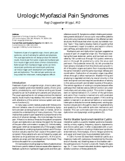
Pelvic & Acetabular Fractures Pelvis Pelvic & Acetabular Fracture Treatment Solutions Operative Technique Matta Asnis III Hoffmann Matta Hoffmann Asnis III Pelvic & Acetabular Fracture Treatment Solutions Acknowledgments Stryker acknowledges Joel Matta, M.D. and Henry Claude Sagi, M.D. for their support in the preparation of this brochure. This publication sets forth detailed recommended procedures for using Stryker Osteosynthesis devices and instruments. It offers guidance that you should heed, but, as with any such technical guide, each surgeon must consider the particular needs of each patient and make appropriate adjustments when and as required. A workshop training is recommended prior to first surgery. All non-sterile devices must be cleaned and sterilized before use. Follow the instructions provided in our reprocessing guide (L24002000). Multi-component instruments must be disassembled for cleaning. Please refer to the corresponding assembly/ disassembly instructions. See package insert (V15011, V15013 and V15034) for a complete list of potential adverse effects, contraindications, warnings and precautions. The surgeon must discuss all relevant risks, including the finite lifetime of the device, with the patient, when necessary. Warning: Fixation Screws: Stryker Osteosynthesis bone screws are not approved or intended for screw attachment or fixation to the posterior elements (pedicles) of the cervical, thoracic or lumbar spine. 2 Contents Page 1.Introduction 5 2. Rationale for Stryker Pelvis & Acetabulum Products 6 Matta Pelvic System (MPS) 6 External Fixation 6 Apex Pin Fixation 6 Asnis Screw Fixation 6 HydroSet 6 3. Precautions & Contraindications for Stryker Pelvis & Acetabulum Products7 Precautions 7 Contraindications7 4. Indications, Features & Benefits for the Matta Pelvic System 8 Matta Pelvic System Indications 8 Features and Benefits 8 Plates 8 Screws8 Instruments 9 Trays 9 5. Plate Types of the Matta Pelvic System10 Female Pelvis 10 Male Pelvis 10 6. The Pelvic Ring and Acetabulum – Fracture Types 11 Pelvic Ring 11 Acetabulum 11 7. Assessment of Pelvic Ring and Acetabulum Fractures 12 Inlet Projection 12 Outlet Projection 12 8. Pelvic Ring Fracture Types & Fixation 13 Symphysis Pubis Disruption13 Iliac Fracture 13 Sacroiliac Dislocation 14 Sacroiliac Fracture – Dislocation 14 Sacrum Fracture 15 9. Acetabular Fracture Types & Fixation 16 Posterior Wall 16 Posterior Column 16 Anterior Wall 17 Anterior Column 17 Transverse18 T-Shaped 18 Posterior Column & Posterior Wall 19 Transverse & Posterior Wall 19 Anterior Column Posterior-Hemitransverse 20 Both Column 20 3 Contents - Continued 10. 11. 12. 13. 14. 15. 16. 17. 19. Page Matta Pelvic System – Plate Bending 21 Matta Pelvic System – Screw Fixation 23 Matta Pelvic System –Reduction Instruments 25 External Fixation Pelvic Frame 28 Hoffmann II MRI 28 Apex Pins 28 Hoffmann II MRI-Pin Placement Techniques 29 Hoffmann Xpress Immediate Care 30 Features and Benefits 30 Apex Pin Fixation 31 Technical Details – Self-Drilling/Self-Tapping Apex Pin 31 Asnis III Screw Fixation 32 Features and Benefits 32 Acetabular Articular Fragments Augmentation with HydroSet33 Features and Benefits 33 Ordering Information – MPS Plates34 Ordering Information – MPS Screws35 Ordering Information – MPS Instruments37 Ordering Information – MPS Cases and Trays39 Ordering Information – Hoffmann II MRI Components40 Ordering Information – Hoffmann II MRI Instruments41 Ordering Information – Hoffmann Xpress42 Ordering Information – Apex Pelvic Pins43 Ordering Information – Apex Instruments 44 Ordering Information – Asnis III Screws46 Ordering Information – HydroSet Injectable HA Bone Substitute49 4 Introduction “The perfect restoration of the articular surface and associated osseous architecture” was the goal set forth by R. Judet and E. Letournel in their surgical treatment of fractures of the pelvis and the acetabulum. However, before surgical intervention in a fractured acetabulum can be accepted as a means of treatment, accurate diagnosis based on radiology is essential. As in other conditions, classification also aids in the accurate understanding of these sometimes complex fractures. No one surgical approach is applicable for all acetabulum fractures. After examination of the plain films as well as the CT scan the surgeons should be knowledgeable of the precise anatomy of the fracture they are dealing with. A surgical approach is selected with the expectation that the entire reduction and fixation can be performed through the surgical approach. The Letournel classification was first published in 1961. Apart from some minor early modifications, it has since remained unchanged and is now the most widely used classification system for acetabular fractures. This classification proposes the division of the various fracture types into two large groups: Elementary Fractures comprise those in which a part or all of one or both columns supporting the acetabulum has been detached by a single fracture line. The five elementary fracture types are: - Fracture of the posterior wall - Fracture of the posterior column - Fracture of the anterior wall - Fracture of the anterior column - Transverse fracture Associated Fractures comprise those in which two or more elementary patterns are combined. The five associated fracture types are: - T-shaped fracture - Posterior column and posterior wall fracture - Transverse and posterior wall fractures - A nterior column or anterior wall with posterior hemi-transverse fracture - Both-column fracture Judet and Letournel concluded early on the most important factor in a successful operation was a thorough pre-operative three-dimensional understanding of the X-Rays and fracture pattern. The same is true today. The surgeon’s knowledge, skill and dedication remain the primary determinants of the patient’s outcome, and the Stryker Pelvic & Acetabular Fracture Treatment Solutions seek to facilitate this. 5 Rationale for Stryker Pelvis & Acetabulum Products Matta Pelvic System (MPS) The Matta Pelvic System (MPS) is designed to address all fractures of the acetabulum and pelvis. The shape, material properties, plate malleability and hole spacing of the plates take into account today’s physician’s need for sufficient fatigue strength, excellent transfer of loading forces and a standardized operative technique with broad applicability. The current set also includes a variety of clamps and reduction aids that are most valuable in pelvic and acetabular reduction technique. External Fixation Hoffmann II External Fixation plays a definitive role in the treatment of unstable pelvic fractures using the device as provisional fixation. In contrast to internal fixation, this method has three potential advantages: ease-of-use, versatility and potential to increase OR efficiency. Apex Pin Fixation Solid pin fixation is essential for effective external fixation frames. The Apex Pin uses advanced thread geometry designed to yield outstanding cutting performance and excellent pin fixation. Asnis Screw Fixation Asnis III 6.5mm or 8.0mm cannulated screws can be utilized in surgical stabilization of sacroiliac joint disruption and/or sacral fractures using a minimally invasive approach. HydroSet HydroSet injectable HA bone void substitute can be utilized in comminuted posterior wall fractures as an effective osteoconductive and osteointegrative material, as well as to help support pelvic bone fragments. 6 Precautions & Contraindications for Stryker Pelvis & Acetabulum Products Precautions* Stryker Osteosynthesis systems have not been evaluated for safety and compatibility in MR environment and have not been tested for heating or migration in the MR environment, unless specified otherwise in the product labeling or respective operative technique. Contraindications* The physician’s education, training and professional judgment must be relied on to choose the most appropriate device and treatment. • Obesity. An overweight or obese patient can produce loads on the implant that can lead to failure of the fixation of the device or to failure of the device itself. Conditions presenting an increased risk of failure include: • Any active or suspected latent infection, or marked local inflammation in or about the affected area. • Patients having inadequate tissue coverage over the operative site. • Compromised vascularity that would inhibit adequate blood supply to the fracture or the operative site. • Any mental or neuromuscular disorder that would create an unacceptable risk of fixation failure or complications in postoperative care. • Bone stock compromised by disease, infection or prior implantation that cannot provide adequate support and/or fixation of the devices. • Implant utilization that would interfere with anatomical structures or physiological performance. • Other medical or surgical conditions that would preclude the potential benefit of surgery. • Material sensitivity, documented or suspected. * Please refer also to Precautions and Contraindications listed in the respective Instructions for Use: V15011, V15013, V15034, 90-01616. 7 Indications, Features & Benefits for the Matta Pelvic System Matta Pelvic System Indications • • • • • • • Acetabulum fracture Pelvic Ring fracture Sacrum fracture Ilium fracture Sacroiliac joint dislocations Symphysis Pubis disruption Revision surgery of pseudoarthroses, non-unions and malunions • Osteotomies • Pelvic arthrodeses Features and Benefits Plates Stainless steel cold-worked and Variety of rigid and flexible plates annealed plates allows excellent fit to pelvis surface characteristics. Curved Plates for male and fe- Excellent precontoured fit to pelvic male pelvis brim radii contribute to broader indi- cations. Dedicated pubic symphysis Plate thickness offers increased stabilplates ity and anatomical plate shape may reduce bending needs. Equal hole spacing on plates Great operative flexibility for screw & plate placement. Round and tapered plate edges Facilitation of plate sliding sub-mus- cularly. Increased screw angulation with Optimized for better screw placement 3.5mm screws options especially for posterior wall fixations. Screws Compatibility of 3.5/4.5mm Flexibility in screw choice according to screws with all plates bony structures. Self-tapping cortical screws Quick, simple and more efficient screw placement. Low screw head profile in plate Helps to prevent screw head promihole nence. 8 Indications, Features & Benefits for the Matta Pelvic System Instruments Range of reduction instruments Great variety of reduction forceps and optimized clamp design offer many options for repositioning. Advanced plate bender Excellent three dimensional bending and curving of MPS Plates. Screwdriver Holding Sleeve Efficiency in screw pick-up and inser- tion as well as removal via “no-touch” technique. Elastosil or Canevasit handles Surgeon can choose handle according to his/her preference. Four options of reduction pins Great flexibility to select pin option. (ø5mm or ø6mm and 150mm or 180mm length) Specific Nerve Retractors Availability of 2 sizes creates potential for excellent soft tissue protection. Spiked Disk Usability options with reduction for- ceps and ball spike for increased bone contact. MPS Plate Templates Allow plate bending away from opera- tive field. Trays Four MPS Cases with modular Flexibility for storage and sterilization. case design Dedicated Basic Instruments Options offer intra-operative freedom Case with all instruments for of choice and comfort to surgeon. three screw sizes Pre-formed inserts for Basic Logical instrument arrangement and instruments easy access to the instruments. 9 Plate Types of the Matta Pelvic System Female Pelvis Radius 88mm Male Pelvis Radius 108mm Curved and Straight Plates Hard (cold-worked) material, 2.5mm thick, 16mm spacing between the holes. Flex Plates Soft (annealed) material, 2.5mm thick, 12mm spacing between the holes, higher malleability than in hard plates. Symphysis Plates Hard (cold-worked) material, 3.2mm thick, 16mm spacing between the holes, 75mm radius. 10 The Pelvic Ring and Acetabulum – Fracture Types Pelvic Ring Fracture Types: - Pubis Symphysis, Pubis Disruption Ilium Fracture Sacroiliac Dislocation Sacroiliac Fracture Dislocation - Sacrum Fracture Acetabulum Fracture Types: Elementary Fractures - Posterior Wall Posterior Column Anterior Wall Anterior Column Transverse Associated Fractures - T-Shaped Posterior Column & Posterior Wall Transverse & Posterior Wall Anterior Column PosteriorHemitransverse - Both Column 11 Assessment of Pelvic Ring and Acetabulum Fractures The evaluation of a pelvic injury has to be based on repeated checks of the patient’s vital parameters, a detailed clinical examination and a structured radiographic evaluation. Emergency decisions can usually be based on a pelvis AP X-Ray, whereas the detailed classification is assigned after additional oblique projections. Inlet Projection Positioning for Inlet projection (Fig.1) and drawing of the X-Ray appearance obtained from the Inlet projection (Fig 1a). Fig 1a Fig 1 Outlet Projection Positioning for Outlet projection (Fig 2) and drawing of the X-Ray appearance obtained from the Outlet projection (Fig 2a). Fig 2a Fig 2 12 Pelvic Ring Fracture Types & Fixation Symphysis Pubis Disruption Approach: The Symphysis (Anterior)/Pfannenstiel approach to the the anterior pelvic ring represents a standard for ORIF of a disrupted Symphysis Pubis. Fixation: • Isolated Symphysis Pubis Disruptions can be fi xed using a dedicated MPS Symphysis four-hole or six-hole Plate. Reduction/Fixation through the Symphysis (Anterior) Surgical Approach (Pfannenstiel Type Aapproach). Iliac Fracture Approach: Fractures of the Ilium can be operated through the first window using the Ilioinguinal approach or a Posterior Pelvic Ring surgical approach is used. Fixation: • One 6.5mm partially threaded cancellous screw is inserted from the anterior-inferior iliac spine, passing 1cm to 2cm above the acetabulum. Reduction/Fixation through the Ilioinguinal or Posterior Pelvic Ring Surgical Approach. • Additionally a 3.5mm independent lag screw in the iliac crest is placed starting from the anterior branch. • One MPS Straight four-hole Plate can be used over the fracture line in the area of the pelvic brim. 13 Pelvic Ring Fracture Types & Fixation Sacroiliac Dislocation Approach: Sacroiliac Dislocations can be operated through the Posterior or Anterior Pelvic Ring approach. Fixation: • A sacroiliac dislocation is fi xed by using a 6.5 or 8.0mm Asnis III cannulated iliosaccral screw. Reduction/Fixation through the Posterior or Anterior Pelvic Ring Surgical Approach. Sacroiliac Fracture – Dislocation Approach: A Posterior Pelvic Ring surgical approach is used to reduce/fi x a sacroiliac fracture dislocation. Fixation: • One 4.5 or 6.5mm independent lag screw is placed starting from the posterior-inferior iliac spine to stabilize the reduction of the inferior aspect of the iliac wing. • One MPS Flex six-hole Plate stabilizes the reduction of the iliac crest. Reduction/Fixation through the Posterior Pelvic Ring Surgical Approach. • One 6.5 or 8.0mm Asnis III cannulated ilio-sacral lag screw fi xes the sacroiliac joint. 14 Pelvic Ring Fracture Types & Fixation Sacrum Fracture Approach: A Posterior Pelvic Ring surgical approach allows an ORIF of Sacrum Fractures. Fixation: • A sacrum fracture is fi xed by placing two 6.5 or 8.0mm Asnis III cannulated lag screws (preferably 16mm thread). Alternatively a 6.5mm cancellous screw is placed into the S1 or S2 vertebral bodies through the lateral iliac wing. Reduction/Fixation through the Posterior Pelvic Ring Surgical Approach. 15 Acetabular Fracture Types & Fixation Posterior Wall Approach: Posterior Wall Fractures are reduced/ fi xed through the Kocher-Langenbeck approach. Fixation: • Two 3.5mm independent lag screws initially fi x the fragments with the desired anatomical reduction. • One MPS Curved R108 six or seven-hole Plate or alternatively a MPS Flex eight-hole Plate spans the fragments along its axis (neutralization plate). Reduction/Fixation through the Kocher-Langenbeck Surgical Approach. Posterior Column Approach: A Kocher-Langenbeck approach is used to reduce/fi x the Posterior Column. Fixation: • Definitive fi xation can be started with an independent lag screw from the distal fragment into the posterior buttress of the ilium. Reduction/Fixation through the Kocher-Langenbeck Surgical Approach. • One MPS Curved six-hole Plate, alternatively, a Flex eight-hole plate along the acetabular margin maintains the reduction. 16 Acetabular Fracture Types & Fixation Anterior Wall Approach: Anterior Wall Fractures can be fi xed using the Ilioinguinal surgical approach. Fixation: • One or two independent lag screws fi x the reduced fragments. • One MPS Curved Plate bridges the fragment on the pelvic brim from the iliac fossa to the intact part of the pubic ramus. Reduction/Fixation through the Ilioinguinal Surgical Approach. Anterior Column Approach: The Ilioinguinal or the Modified Stoppa surgical approach can be used to reduce/fi x Anterior Column Fractures. Fixation: • An independent lag screw maintains the reduction. • Then a MPS Curved 10-hole Plate is shaped to adapt itself to the pelvic brim going from the pubic tubercle to the vicinity of the sacroiliac joint. A minimum of two screws should be placed beyond the fracture line. Reduction/Fixation through the Ilioinguinal or Modified Stoppa Surgical Approach. • All central screws should be parallel to the quadrilateral surface. 17 Acetabular Fracture Types & Fixation Transverse Approach: The Kocher-Langenbeck approach can be used to access Transverse Fractures. Fixation: • The posterior column is stabilized with an independent 3.5 or 4.5mm lag screw and an MPS Flex six-hole Plate (neutralization plate). • The anterior column is stabilized with an independent 4.5mm lag screw. Reduction/Fixation through the Kocher-Langenbeck Surgical Approach. T-Shaped Approach: A Kocher-Langenbeck or alternatively an Extended Iliofemoral approach are options to perform an ORIF of T-Shaped Fractures. Fixation: • The posterior column is stabilized with an independent 3.5 or 4.5mm lag screw and an MPS Curved or MPS Flex Plate (neutralization plate). Reduction/Fixation through the Kocher-Langenbeck or Extended Iliofemoral Surgical Approaches. • The anterior column is then fi xed with an independent 4.5mm lag screw. 18 Acetabular Fracture Types & Fixation Posterior Column & Posterior Wall Approach: Combined Posterior Column & Posterior Wall Fractures can be reduced/fi xed using the KocherLangenbeck approach. Fixation: • Initial fi xation of the posterior column is done with an independent lag screw and/or a five or six-hole plate. Reduction/Fixation through the Kocher-Langenbeck Surgical Approach. • If the posterior wall fragment is large enough, it should be fi xed into its bed with one or two lag screws. • Definitive stabilization of the posterior wall and column is obtained by adding a seven or eighthole MPS Curved Plate buttressing the posterior wall and anchored securely to the ilium and ischium using 3.5mm screws. Transverse & Posterior Wall Approach: Reduction/Fixation of Transverse & Posterior Wall Fractures can be done through the Kocher-Langenbeck approach. Fixation: • Two 3.5 or 4.5mm independent lag screws stabilize the transverse fracture component. Reduction/Fixation through the Kocher-Langenbeck Surgical Approach. • One or two independent 3.5mm lag screws maintain the reduction of the posterior wall fragment. • An MPS Flex eight-hole Plate or alternatively a six or seven-hole MPS Curved Plate is applied to buttress the posterior wall. 19 Acetabular Fracture Types & Fixation Anterior Column Posterior-Hemitransverse Approach: Anterior Column PosteriorHemitransverse Fractures can be fi xed using the Ilioiguinal approach. Fixation: • Initial fi xation of the posterior column is provided by a 3.5 or 4.5mm lag screw through the pelvic brim. • Stabilization of the anterior column with one or two individual 3.5 or 4.5mm lag screws from the ASIS (Anterior Superior Iliac Spine) and/ or the AIIS (Anterior Inferior Iliac Spine). Reduction/Fixation through the Ilioinguinal Surgical Approach. • An MPS Curved Plate can then be placed along the pelvic brim starting in the sciatic buttress, just anterior to the SI joint. Both Column Approach: Both Column Fractures are operated through the Ilioinguinal or Extended Iliofemoral approach. Fixation: • Two 3.5mm independent lag screws in the iliac crest fi x the reduction of the wing fracture lines. • One or two 3.5mm independent lag screws should run from the upper aspect of the true pelvis to fi x the reduction of the posterior column. • One independent lag screw fixes the reduction of a separated posterior fragment of the pelvic brim, just in front of the sacroiliac joint. Reduction/Fixation through the Ilioinguinal or Extended Iliofemoral Surgical Approaches. • One eight-hole MPS Flex Plate should be placed along the iliac crest to stabilize the iliac wing fracture. • One long MPS Curved 10 or 12-hole Plate along the pelvic brim stabilizes the anterior column. 20 Matta Pelvic System – Plate Bending The plate must be shaped correctly to fit with precision to the reduced contour of the pelvis or the acetabulum. The fitting of the plate on the bony surface should be as precise as possible so the insertion of screws will not cause the fragments to change position (Figure 1). During plating and screw insertion, it is always the bone that is drawn toward the plate, not the plate toward the bone (Figure 2). In certain instances it may be advantageous to contour the plate to a slight mis-match with the bone. Subsequent insertion and tightening of the screws causes the plate to manipulate the bone, therefore aiding in obtaining or maintaining the reduction. Figure 1 – Correct If the plate fits precisely. Figure 2 – Incorrect When tightening the screws, the fragment will be drawn towards the plate. 21 Matta Pelvic System – Plate Bending For a plate to apply perfectly on a bone, it must be possible to shape it in all directions: • Curve it to adapt to the shapes of the iliac crest or the upper aspect of the pelvic brim, or to make it possible to span a fragment of the posterior wall or posterosuperior wall, along its main axis (Figure 3a, 3b). • Bend it along its main axis (Figure 4a, 4b). Figure 3a Figure 4a Figure 3b It is an important fact that the plate must be bent, as far as possible, in the spaces between the holes, so as to alter them as little as possible (Figure 6). It is a well-known fact that rectangular plates do not bend in a regular fashion • Twist it along its main axis, to give it a helicoidal shape (Figure 5a, 5b). Figure 4b but rather at their holes (Figure 7). Sherman type plates with equal hole spacing and narrowing between the holes, are best adapted to such shaping and allow for a more precise adaptation to the pelvic contours. Curving should always be performed first, since it is very difficult to curve the plate after a main axis bend or twist has been made. Figure 5a Figure 5b Figure 6 Figure 7 22 Matta Pelvic System – Screw Fixation 3.5/4.5mm MPS Screws used with MPS Plates The 3.5mm self-tapping cortical screws are the recommended screws for plate fixation and are best adapted to the pelvic bone. The 4.5mm cortical screw is often too large and its voluminous head creates a slight prominence above the plates, which may lead to soft tissue irritation in certain applications. Furthermore, the plate holes are designed to accept 3.5mm screws inserted at extreme angles, up to 35o in all directions. This capability is essential, as it must be possible to avoid penetrating the hip joint or to be able to drive a screw obliquely in the area of the iliac bone, avoiding a previously inserted, isolated screw. Therefore, these screws should only be used to fix a plate in exceptional cases (symphysis pubis fixation), as when a smaller screw does not get sufficient purchase. 35º 4.5mm cortical or 6.5mm cancellous screws used as Lag Screws: • • Screw 1: From the crest of the anterior border into the iliac wing. Screw 2: From the anteroinferior iliac spine, passing 1 or 2cm above the acetabulum (length 100 –120mm). • Screw 3: Along the axis of the anterior column, starting from the posterior aspect of the iliac wing pillar approx. 3-4cm above the acetabulum. This screw is very useful to secure a transverse fracture or an anterior column, through an extended ilio–femoral approach. • • • Screw 4: From posterior to anterior part of the iliac wing. Screw 5: From posterior superior iliac spine to anterior part of the iliac wing to reduce a sacroiliac joint fracture dislocation. Screw 6: Along the axis of the posterior column. For each of these lag screw insertions, it is essential to drill intermittently, step-by-step, and change the direction of the drill if you feel penetration of a cortex. Remain in the correct axis and advance the drill as far as possible. 23 Matta Pelvic System – Screw Fixation Independent Interfragmentary Compression Often, independent (isolated) interfragmentary lag screws are used in conjunction with pelvic and acetabular fracture fixation. The screw thread takes no purchase in the near fragment because the screw has a shaft with no thread and/or the drill hole in the near fragment is equal to the outside diameter of the screw. Therefore, the cortex in the near fragment has to be overdrilled to create a “gliding” hole. Overdrilling the cortex in this manner allows the screw thread to take purchase in the bone of the opposite fragment. Drill Guides Use the Double Drill Guide REF 702417 and the 4.5mm Drill or Double Drill Guide REF 702418 and Drill 3.5mm for screws 3.5mm to overdrill the near cortex. Insert the opposite side of the relevant Drill Guide into the pre-drilled hole for precise axial alignment and use the corresponding drill for the corehole of the screw. This procedure should prevent the loss of reduction and fixation during screw insertion. 24 Matta Pelvic System – Reduction Instruments The Matta Pelvic Systems forceps and other reduction instruments are designed for use with the irregular, large and flat bony surfaces of the pelvic region. The angles and length of the jaws are designed to accommodate the innominate bone from the crest to the pelvic brim and to provide flexibility for various surgical approaches. Reduction of acetabular fractures are best performed on the othopaedic extension table allowing distal and lateral traction. Reduction Forceps with Points Faraboef Forceps 702926 – L130mm 702927 – L200mm 702928 – L190mm 702929 – L250mm These forceps can be applied directly to the bone´s surface or be used with shallow drill holes. The versatile Faraboef clamps can be used to grasp and manipulate the iliac wing, or as reduction forceps with provisional screws of either 3.5mm or 4.5mm diameter. 25 Matta Pelvic System – Reduction Instruments Matta Reduction Forceps Reduction Forceps for Screws, Jungbluth verbrugge Forceps 702921 – Small 702922 – Large 702924 – ø4.5mm 702925 – ø3.5mm Right 702947 – ø3.5mm Left 700641 These two oblique forceps are designed so that the handles angle away from both the surgeon`s sight line and critical soft tissue structures. The sharp points provide a secure hold on the pelvic surfaces, while the balls prevent penetration of bone with a thin cortex. These two forceps have been designed to be used with either 3.5mm or 4.5mm screws (3.5mm version available in left or right option). Screws inserted on the opposite side of the fracture allow considerable reduction forces and manipulation in all three planes. For easier reduction, there are times when only one screw is inserted, requiring the application of one jaw of the Verbrugge forceps. The other jaw takes direct hold on another part of the bony surface. 26 Example: The angle of the greater sciatic notch. Matta Pelvic System – Reduction Instruments Reduction Forceps, King Tong Sciatic Nerve Retractor Straight Ball Spike 702930 – 2x1 Jaws 702948 – 1x1 Jaws 702915 – Small 702916 – Large 702911 This long forceps with threepointed ball tips allow reduction of perpendicular fractures. The long handles provide increased leverage for difficult reductions. These forceps are also available in a 1x1 jaws version. Two sizes are available to enable better soft-tissue retraction. This reduction instrument is used as a pusher with pointed ball tip to reduce bone fragments. To distribute the reduction forces over an increased area, the Spiked Disc can be clipped onto the ball tip. 27 External Fixation Pelvic Frame Hoffmann II MRI External Fixation System offers rapid application in times of hemodynamic compromise with the ability to access the abdomen and pelvic viscera for secondary procedures. External Fixation is most appropriate for open-book pelvic fractures in which the posterior structures are at least partially intact, or lateral compression injuries with internal rotation of the hemipelvis. Hoffmann II MRI Features �Snap-Fit’ connections Benefits Rapid frame construction. Single point of tightening Fast and easy frame construction. Small, lightweight clamps Visualization and access to the fracture site. Color–coded components Quick and easy identification. Non-ferromagnetic materials No frame displacement using MRI. Apex Pins Features Independent, multiplanar pin Benefits Stable frame construction. placement Self-drilling tip 316L Stainless Steel No pre-drilling necessary. MRI Conditional. Double helical flute Excellent pin/bone interface. Cylindrical thread design Great purchase and pull-out resistance1, 2, 3. Pubis symphysis dislocation. ExFix stabilization. 1 Stryker Test Report BML 10-183; Pull-out test for several Apex pins, Labor job number V10219; 2010. 2 Stryker Test Report RA 05-168; Clinical Assessment - Hoffmann II; Hoffmann II Compact and Apex Pins; 2010. 3 Fachhochschule Hamburg; Vergleichende biomechanische Untersuchung von “Fixateur Externe-Pins”; 1997. 28 Definitive treatment. Hoffmann II MRI - Pin Placement Techniques The insertion of two K-wires, one on the medial side and one on the lateral side of the iliac wing, provides an accurate targeting method. They identify both borders of the crest and plane of the ilium toward the acetabular roof, helping to ensure safe and correct placement of the Apex pins between the two tables of the ilium. Avoid penetration of the medial cortex in order to limit pelvic viscera risk. Illiac Crest Pin Placement. Illiac Crest and Inferior Illiac spine combined Pin Placement. Due to the supraacetabular bone mass being significantly thicker, a frame construct mounted on a single Apex pin offers improved rigidity. Care has to be taken not to injure the lateral femoral cutaneous nerve during pin insertion. The orientation of the Apex pin can be perpendicular to the body axis or directed somewhat cephalad, depending on the location of the starting point in relation to the greater sciatic notch. Illiac Spine Pin Placement. 29 Hoffmann Xpress Immediate Care Features Benefits Light weight Clamps Pin clamp with integrated post Removable/reversible Pin Insert Coupling with �Snap-Fit’ mechanism 360º independent rotation on either side of the Universal Coupling MRI conditional Sterile packed 30 Visualization and access to the fracture site. Complete versatility of the frame. Fast conversion from pin-to-tube, into tube-to-tube coupling. Allows for a non-slip connection to the rod or pin. Unlimited frame configuration options. No additional risk of MRI injury for the patient in a MRI environment up to 3.0 Tesla. Safe and fast for acute trauma situations. Apex Pin Fixation Technical Details – Self-Drilling/Self-Tapping Apex Pin Pin Design The self-drilling tip of the Apex Pin acts like a new, sharp drill bit every time, and therefore, pre-drilling is not necessary. Combined with unique cutting geometry, this one-step procedure allows the pin to maintain a reduced insertion temperature due to decreased friction. A double helical flute creates a homogeneous thread profile that transports bone chips out of the drill hole for improved pin/bone interface. The highly advanced cutting geometry allows for more precise pin insertion with reduced insertion time and temperature for optimal performance. The U-shaped thread maximizes contact with the bone and controls stress distribution on the pin/bone interface by optimizing radial tension. The cylindrical thread is designed for good bone purchase, and pull-out resistance1, 2, 3 , and offers the possibility to backing out the pin without compromising fixation. 1 Stryker Test Report BML 10-183; Pull-out test for several Apex pins, Labor job number V10219; 2010. 2 Stryker Test Report RA 05-168; Clinical Assessment - Hoffmann II; Hoffmann II Compact and Apex Pins; 2010. 3 Fachhochschule Hamburg; Vergleichende biomechanische Untersuchung von “Fixateur Externe-Pins”; 1997. U-shaped thread Self-tapping action Self-drilling tip 31 Asnis III Screw Fixation The Asnis III Cannulated Screw Systems have been designed to optimize surgical outcomes while simplifying procedures. The systems incorporate several features intended to enhance screw placement, insertion and removal. Features Benefits Low Profile Screw Head Stainless Steel (316LvM) Shaft and Core Diameter Equal Self-drilling/self-tapping design Large diameter Guide wires Percutaneous screw placement Reduced potential for soft-tissue irritation. Excellent strength. Added strength. Improves operating efficiency. More precise screw placement. Potential for minimal invasive surgery. Partially threaded Interfragmentary compression. 8mm Long screws Excellent stability4 . Asnis III Pelvic Screws Especially 8.0mm partially threaded screws with length of 125mm up to 180mm are used as well as 6.5mm screws with 20mm thread up to 120mm length. 4 Stryker Test Report BML 01/033; Biomechanical Tests on Cannulated Screws; Asnis III diam. 8mm, Labor job number S01012; 2001. 32 Acetabular Articular Fragments Augmentation with HydroSet Fractures of the posterior wall of the acetabulum comprise one-fourth to one-third of all acetabular fractures, representing the most common pattern of fracture of the acetabulum.* In fractures with intra-articular comminution and intercalary osteochondral fragments, one can use HydroSet calcium phosphate cement, an injectable, sculptable bone substitute to help support bone fragments during the surgical procedure**. It is recommended that the femoral head is used as a template to orientate and to reduce the different articular fragments. Features Benefits Excellent wet-Field Characteristics Fast Setting Isothermic Injectable or Manual Implantation Osteoconductive Radiopaque Decreases potential for waiting time. Limited waiting time. No damaging heat is released to the surrounding tissue. Greater number of options for the surgeon and the opportunity to sculpt HydroSet. The composition of hydroxyapitite closely matches that of bone mineral thus. Impenetrable by X-Ray. Visible under fluoroscopy. * Baumgaertner MR. Fractures of the posterior wall of the acetabulum. J Am Acad Orthop Surg. 1999; 7:54–65. Aho AJ, Isberg UK, Katevuo VK. Acetabular posterior wall fractures: 38 cases followed for 5 years. Acta Orthop Scand. 1986; 57:101–5. Letournel E, Judet R. Fractures of the Acetabulum. 2nd ed. Berlin, Germany: Springer Verlag; 1993. ** The current cement acts only as a temporary support media and is not intended to provide structural support. 33 Ordering Information – MPS Plates MPS Curved R108 Plate Stainless Steel REF 425604 425605 425606 425607 425608 425609 425610 425611 425612 425613 425614 425615 425616 425618 425620 MPS Straight Plate Plate Holes Length mm Titanium REF 58.54 PN/A 74.55 PN/A 90.56 PN/A 106.57 N/A 122.58 PN/A 138.59 N/A 154.510 PN/A 170.511 N/A 186.512 PN/A 202.513 N/A 218.514 PN/A 234.515 N/A 250.516 PN/A 282.518 N/A 314.520 N/A MPS Curved R88 Plate Stainless Steel REF 425654 425655 425656 425657 425658 425659 425660 425661 425662 425663 425664 425665 425666 425668 425670 Stainless Steel REF 425702 425703 425704 425705 425706 425707 425708 425709 425710 425711 425712 425713 425714 425715 425716 425718 425720 Plate Holes Length mm Titanium REF 26.52 N/A 42.53 PN/A 58.54 PN/A 74.55 N/A 90.56 PN/A 106.57 N/A 122.58 PN/A 138.59 N/A 154.510 PN/A 170.511 N/A 186.512 PN/A 202.513 N/A 218.514 PN/A 234.515 N/A 250.516 PN/A 282.518 N/A 314.520 N/A MPS Flex Plate (annealed) Plate Holes Length mm Titanium REF 58.54 PN/A 74.55 PN/A 90.56 PN/A 106.57 N/A 122.58 PN/A 138.59 N/A 154.510 PN/A 170.511 N/A 186.512 PN/A 202.513 N/A 218.514 PN/A 234.515 N/A 250.516 PN/A 282.518 N/A 314.520 N/A Stainless Steel REF 425754 425755 425756 425757 425758 425759 425760 425761 425762 425763 425764 425765 425766 425767 425768 425770 425772 Plate Holes Length mm Titanium REF 46.54 PN/A 58.55 N/A 70.56 PN/A 82.57 N/A 94.58 PN/A 106.59 N/A 118.510 PN/A 130.511 N/A 142.512 PN/A 154.513 N/A 166.514 PN/A 178.515 N/A 190.516 PN/A 202.517 N/A 214.518 PN/A 238.520 N/A 262.522 N/A MPS Symphysis Plate, R75 Stainless Steel REF 425794 425796 Plate Holes Length mm Titanium REF 58.54 PN/A 90.56 PN/A P Recommended set item 34 Ordering Information – MPS Screws 3.5mm Cortical Screw, Self–Tapping Stainless Steel REF Screw Length mm 4.5mm Cortical Screw, Self-Tapping Titanium REF 338610 338612 338614 338616 338618 338620 338622 338624 338626 338628 338630 338632 338634 338636 338638 338640 338642 338644 338645 338646 338648 338650 338655 338660 338665 338670 338675 338680 338685 338690 338695 338700 338705 338710 10 N/A 12 PN/A 14 PN/A 16 PN/A 18 PN/A 20 PN/A 22 PN/A 24 PN/A 26 PN/A 28 PN/A 30 PN/A 32 PN/A 34 PN/A 36 PN/A 38 PN/A 40 PN/A 42 N/A 44 N/A 45 PN/A 46 N/A 48 N/A 50 PN/A 55 PN/A 60 PN/A 65 PN/A 70 PN/A 75 PN/A 80 PN/A 85 PN/A 90 PN/A 95 PN/A 100 PN/A 105 PN/A 110 PN/A 338715 338720 115 120 Stainless Steel REF 340614 340616 340618 340620 340622 340624 340626 340628 340630 340632 340634 340636 340638 340640 340642 340644 340646 340648 340650 340652 340654 340655 340656 340658 340660 340662 340664 340665 340666 340668 340670 340672 340675 340676 340680 340685 340690 340695 340700 340705 340710 340715 340720 340725 340730 340735 340740 340745 340750 N/A N/A Screw Length mm Titanium REF 14 PN/A 16 PN/A 18 PN/A 20 PN/A 22 PN/A 24 PN/A 26 PN/A 28 PN/A 30 PN/A 32 PN/A 34 PN/A 36 PN/A 38 PN/A 40 PN/A 42 PN/A 44 PN/A 46 PN/A 48 PN/A 50 PN/A 52 PN/A 54 PN/A 55 N/A 56 PN/A 58 PN/A 60 PN/A 62 N/A 64 N/A 65 PN/A 66 N/A 68 N/A 70 PN/A 72 N/A 75 PN/A 76 N/A 80 PN/A 85 PN/A 90 PN/A 95 PN/A 100 PN/A 105 PN/A 110 PN/A 115 PN/A 120 PN/A 125 130 135 140 145 150 N/A N/A N/A N/A N/A N/A Special Order P Recommended set item 35 Ordering Information – MPS Screws 6.5mm CANCELLOUS Screw, 16mm Thread Stainless Steel REF Screw Length mm 341030 341035 341040 341045 341050 341055 341060 341065 341070 341075 341080 341085 341090 341095 341100 341105 341110 341115 341120 341125 341130 341135 341140 341145 341150 Titanium REF 30 N/A 35 N/A 40 N/A 45 N/A 50 PN/A 55 PN/A 60 PN/A 65 PN/A 70 PN/A 75 PN/A 80 PN/A 85 PN/A 90 PN/A 95 PN/A 100 PN/A 105 PN/A 110 PN/A 115 PN/A 120 PN/A 125 PN/A 130PN/A 135 N/A 140 N/A 145 N/A 150 N/A 6.5mm CANCELLOUS Screw, 32mm Thread Stainless Steel REF 342045 342050 342055 342060 342065 342070 342075 342080 342085 342090 342095 342100 342105 342110 342115 342120 342125 342130 342135 342140 342145 342150 Screw Length mm Titanium REF 45 N/A 50 PN/A 55 PN/A 60 PN/A 65 PN/A 70 PN/A 75 PN/A 80 PN/A 85 PN/A 90 PN/A 95 PN/A 100 PN/A 105 PN/A 110 PN/A 115 PN/A 120 PN/A 125 PN/A 130 PN/A 135 N/A 140 N/A 145 N/A 150 N/A Washer Stainless Steel REF 390016 390019 Diameter mm Thickness mm Titanium REF 13.0 P1.5 N/A 9.0 P1.0 N/A For the full range of standard non-self-tapping screws, please refer to the Stryker Osteosynthesis Product Catalog 36 Special Order P Recommended set item Ordering Information – MPS Instruments REFDescription 700351 PCalibrated Drill Bit ø2.5mm × 180mm, AO Fitting 700355 PCalibrated Drill Bit ø2.5mm × 230mm, AO Fitting 700353 PDrill Bit ø3.5mm × 180mm, AO Fitting 700356 PCalibrated Drill Bit ø3.2mm × 180mm, AO Fitting 700357 PCalibrated Drill Bit ø3.2mm × 230mm, AO Fitting 700354 PDrill Bit ø4.5mm × 180mm, AO Fitting 702804 P Tap ø3.5mm × 180mm, AO Fitting 702806 P Tap ø4.5mm × 180mm, AO Fitting 702807 P Tap ø6.5mm × 180mm, AO Fitting 702811 PCountersink ø6.0mm × 100mm, AO Fitting 702812 PCountersink ø8.0mm × 100mm, AO Fitting 702842 P 702843 P Screwdriver Hex 2.5mm, L280mm Screwdriver Hex 3.5mm, L300mm 702851 PScrewdriver Hex 2.5mm, L165mm, AO Fitting 702853 PScrewdriver Hex 3.5mm, L165mm, AO Fitting 702861 PScrewdriver Holding Sleeve for Screws ø3.5mm 702862 PScrewdriver Holding Sleeve for Screws ø4.5/6.5mm 702417 P 702418 P Double Drill Guide ø3.2/4.5mm Double Drill Guide ø2.5/3.5mm 702876 PDepth Gauge 0-110mm, for Screws ø2.7/3.5/4.0mm, Titanium 702877 PDepth Gauge 0-150mm, for Screws ø4.5/6.5mm, Titanium 702911 P Straight Ball Spike 702912 P Straight Ball Spike, AO Fitting 702923 P Spiked Disk 702427 P T-Handle small, AO Quick Coupling 702428 PSmall Teardrop-Handle, AO Quick Coupling 702429 PLarge Teardrop-Handle, AO Quick Coupling 702915 P 702916 P Small Sciatic Nerve Retractor Large Sciatic Nerve Retractor 390083 PReduction Pin ø5.0mm L150mm, AO Fitting 390084 PReduction Pin ø5.0mm L180mm, AO Fitting 900106 P Screw Forceps P Recommended set item 37 Ordering Information – MPS Instruments REF Description 710312 P 710313 P 710315 P 710316 P 710318 P 710319 P 710321 P 710322 P Template MPS Flex plate, 8H Template MPS Flex plate, 18H Template MPS Straight plate, 8H Template MPS Straight plate, 18H Template MPS Curved R108 plate, 8H Template MPS Curved R108 plate, 18H Template MPS Curved R88 plate, 8H Template MPS Curved R88 plate, 18H 702902 P Bending Iron for Pelvic plates 702903 P Bending Plier 702921 P 702922 P Small Repositioning Forceps, type Matta Large Repositioning Forceps, type Matta 702924 P 702925 P 702947 P Repositioning Forceps for Screws ø4.5mm Repositioning Forceps for Screws ø3.5mm, Right Repositioning Forceps for Screws ø3.5mm, Left 702926 P 702927 P Small Reduction Forceps with Points L130mm Large Reduction Forceps with Points L200mm 702928 P 702929 P Faraboef Forceps L190mm Faraboef Forceps L250mm 702930 P 702948 P Repositioning Forceps, 2×1 Jaws Repositioning Forceps, 1×1 Jaws 702932 P Repositioning Forceps with Serrated Jaws L140mm 700641 P Modified Verbrugge Forceps 700647 P Curved Chisel Optional Instruments 390086 Reduction Pin ø6.0mm × 150mm, AO Fitting 390087 700367 702845 702846 702847 702848 702849 710311 710314 710317 710320 Reduction Pin ø6.0mm × 180mm, AO Fitting Large T-Handle, AO Quick Coupling Screwdriver Hex. 2.5mm, L280, with Canevasit Handle Screwdriver Hex. 3.5mm, L300, with Canevasit Handle Straight Ball Spike L300mm, with Canevasit Handle Canevasit Handle Small, AO Coupling Canevasit Handle Large, AO Coupling Template MPS Flex plate, 5H Template MPS Straight plate, 5H Template MPS Curved R108 plate, 5H Template MPS Curved R88 plate, 5H P Recommended set item 38 Ordering Information – MPS Cases and Trays REFDescription REFDescription 901557 PPlastic Base (Implant Case Plates) 901557 PPlastic Base (Implant Case Screws) 901686 PScrew Rack with Lids (Implant Case Screws) 901591Metal Base Optional (Implant Case Plates) 901591Metal Base Optional (Implant Case Screws) 901618 PPlastic Base (Basic Instruments) 901681 PPlastic Lid (Implant Case Plates) 901682 PTray Insert (Implant Case Plates) 901619Metal Base Optional (Basic Instruments) 901687 PPlastic Lid (Basic Instruments) 901683 PRack with Lid # 1 (Implant Case Plates) 901688 PUpper Tray Insert (Basic Instruments) 901684 PRack with Lid # 2 (Implant Case Plates) 901689 PLower Tray Insert (Basic Instruments) 901690 PPlastic Base (Reduction Instruments) 901685 PPlastic Lid (Implant Case Screws) 901691 P Plastic Lid P Recommended set item 39 Ordering Information – Hoffmann II MRI Components REF Description Hoff mann II MRI Components 4921-2-020 Five-Hole Pin Clamp for ø4, ø5, and ø6mm pins 4921-2-060 10-Hole Pin Clamp for ø4, ø5, and ø6mm pins 4921-2-080 Pelvic Clamp for ø4, ø5, and ø6mm pins 4921-1-010 Rod-to-Rod Coupling for ø8mm rods or posts 4921-1-020 Pin-to-Rod Coupling for ø4-5mm pins/ø8mm rods or posts 4921-1-030 Inverted Pin-to-Rod Coupling for ø8mm rods or posts/ø4-5mm pins 4921-2-140 30° Angled Post, ø8mm 4921-2-120 Straight Post, ø8mm ø8mm Rods 174mm (L) 40 5028-8-065 5028-8-100 5028-8-150 5028-8-200 5028-8-250 5028-8-300 5028-8-350 5028-8-400 5028-8-450 Carbon Connecting Rod Carbon Connecting Rod Carbon Connecting Rod Carbon Connecting Rod Carbon Connecting Rod Carbon Connecting Rod Carbon Connecting Rod Carbon Connecting Rod Carbon Connecting Rod 65mm 100mm 150mm 200mm 250mm 300mm 350mm 400mm 450mm 5028-7-030 Semi-Circular Carbon Rod 174mm (L) Ordering Information – Hoffmann II MRI Instruments REF Description Hoff mann II Instruments for MRI System (not for use in the MRI suite) 4920-9-010 Stabilization/Reduction Wrench 4920-9-020 Thumbwheel 4920-9-030 7mm T-Wrench/ø5-6mm Pin Inserter 4920-9-036 7mm Spanner Wrench 4921-9-984 Storage Case Lid 4921-9-983 Storage Case Upper Insert 4921-9-982 Storage Case Lower Insert 4921-9-981 Storage Case Base 41 Ordering Information – Hoffmann Xpress REFDescription Hoffmann Xpress Components 4980-1-010S Universal Coupling �15/15mm 4-5/15mm For Tubes and Curved Rod 15mm �, Pins 4mm, 5mm and 6mm cancellous (shaft �5mm) 4980-2-020S 5-Pin Clamp, 2 Posts For Pins �4mm, 5mm and 6mm and to connect with Universal Coupling For �4, �5 and �6mm pins 4980-2-010S 5-Pin Clamp, 1 Post REF Description Length mm Hoffmann Xpress Components 4980-3-150S Aluminum Tube 150mm 4980-3-210S Aluminum Tube 210mm 4980-3-260S Aluminum Tube 260mm 4980-3-330S Aluminum Tube 330mm 4980-3-440S Aluminum Tube 440mm 4980-3-500S Aluminum Tube 500mm 4980-3-020S Semi Circular Curved Tube �15mm 42 160 x 235 Ordering Information – Apex Pelvic Pins Self Drilling/Self Tapping Stainless Steel REF Diameter mm Thread/Shaft 5018-6-150 5018-3-180 5018-6-180 5018-8-180 5018-5-200 5018-6-200 5018-5-250 5018-7-250 5021-7-150 5021-6-180 5021-8-200 5021-8-250 5.0 5.0 5.0 5.0 5.0 5.0 5.0 5.0 6.0 6.0 6.0 6.0 Stainless Steel REF Diameter mm Thread/Shaft 5015-3-120 5015-4-150 5015-5-150 5015-6-180 5015-7-250 6.0/5.0 6.0/5.0 6.0/5.0 6.0/5.0 6.0/5.0 Total Length mm 150 180 180 180 200 200 250 250 150 180 200 250 Thread Length mm 50 35 50 60 50 60 50 70 50 60 70 80 Cancellous Total Length mm 120 150 150 180 250 43 Thread Length mm 35 40 50 60 70 Ordering Information – Apex Instruments REF Description Apex Instruments 44 5057-0-300 Drill Brace Assembly 5057-0-310 Handle for Drill Brace 4920-9-030 T-Wrench/Pin Inserter, 7mm 5057-1-003 Quick Release Apex Chuck with AO fitting, 3mm 5057-1-004 Quick Release Apex Chuck with AO fitting, 4mm 5057-1-005 Quick Release Apex Chuck with AO fitting, 5mm 5057-1-006 Quick Release Apex Chuck with AO fitting, 6mm 5057-1-110 Drill Guide Handle 5057-1-115 Drill Guide Block, 5 holes, Hoffmann II 5057-1-116 Drill Guide Block, 10 holes, Hoffmann II 5057-1-117 Drill Guide Block, 4 holes, Hoffmann II Compact 5057-1-118 Drill Guide Block, 4 holes, Hoffmann II Compact, Peri Articular Clamp 5057-1-119 Drill Guide Block, 4 holes, Monotube Triax, blue, red 5057-1-120 Drill Guide Block, 2 holes, Monotube Triax, yellow Ordering Information – Apex Instruments REF Description Apex Instruments 5057-4-000 Predrilling Assembly, � 4.0mm, extra short 35mm protection length 5057-5-000 Predrilling Assembly, � 5.0mm, extra short 50mm protection length 5057-6-000 Predrilling Assembly, � 6.0mm, extra short 60mm protection length 5057-3-100 Predrilling Assembly, � 3.0mm, short 33mm protection length 5057-4-100 Predrilling Assembly, � 4.0mm, short 70mm protection length 5057-5-100 Predrilling Assembly, � 5.0mm, short 73mm protection length 5057-6-100 Predrilling Assembly, � 6.0mm, short 90mm protection length 5057-3-200 Predrilling Assembly, � 3.0mm, long 43mm protection length 5057-4-200 Predrilling Assembly, � 4.0mm, long 100mm protection length 5057-5-200 Predrilling Assembly, � 5.0mm, long 113mm protection length 5057-6-200 Predrilling Assembly, � 6.0mm, long 120mm protection length 5057-6-300 Pin Cutter, 4mm, 5mm & 6mm, Extension Handles 5057-9-913 Apex Storage Tray, Metal Lid A 5057-9-912 Apex Storage Tray, Upper Insert 5057-9-911 Apex Storage Tray, Lower Insert 5057-9-910 Apex Storage Tray, Metal Base 45 Ordering Information - Asnis III Screws 6.5mm Implants - 20mm Thread Screws* Stainless Steel Description REF 326040S 326045S 326050S 326055S 326060S 326065S 326070S 326075S 326080S 326085S 326090S 326095S 326100S 326105S 326110S 326115S 326120S Asnis III Cannulated Screw 6.5 × 40mm Asnis III Cannulated Screw 6.5 × 45mm Asnis III Cannulated Screw 6.5 × 50mm Asnis III Cannulated Screw 6.5 × 55mm Asnis III Cannulated Screw 6.5 × 60mm Asnis III Cannulated Screw 6.5 × 65mm Asnis III Cannulated Screw 6.5 × 70mm Asnis III Cannulated Screw 6.5 × 75mm Asnis III Cannulated Screw 6.5 × 80mm Asnis III Cannulated Screw 6.5 × 85mm Asnis III Cannulated Screw 6.5 × 90mm Asnis III Cannulated Screw 6.5 × 95mm Asnis III Cannulated Screw 6.5 × 100mm Asnis III Cannulated Screw 6.5 × 105mm Asnis III Cannulated Screw 6.5 × 110mm Asnis III Cannulated Screw 6.5 × 115mm Asnis III Cannulated Screw 6.5 × 120mm Titanium REF 602640S 602645S 602650S 602655S 602660S 602665S 602670S 602675S 602680S 602685S 602690S 602695S 602700S 602705S 602710S 602715S 602720S 6.5mm Implants - 40mm Thread Screws* Stainless Steel REF Diameter mm Titanium REF Asnis III Cannulated Screw 6.5 × 55mm Asnis III Cannulated Screw 6.5 × 60mm Asnis III Cannulated Screw 6.5 × 65mm Asnis III Cannulated Screw 6.5 × 70mm Asnis III Cannulated Screw 6.5 × 75mm Asnis III Cannulated Screw 6.5 × 80mm Asnis III Cannulated Screw 6.5 × 85mm Asnis III Cannulated Screw 6.5 × 90mm Asnis III Cannulated Screw 6.5 × 95mm Asnis III Cannulated Screw 6.5 × 100mm Asnis III Cannulated Screw 6.5 × 105mm Asnis III Cannulated Screw 6.5 × 110mm Asnis III Cannulated Screw 6.5 × 115mm Asnis III Cannulated Screw 6.5 × 120mm Asnis III Cannulated Screw 6.5 × 125mm Asnis III Cannulated Screw 6.5 × 130mm 602855S 602860S 602865S 602870S 602875S 602880S 602885S 602890S 602895S 602900S 602905S 602910S 602915S 602920S 602925S** 602930S** 326255S 326260S 326265S 326270S 326275S 326280S 326285S 326290S 326295S 326300S 326305S 326310S 326315S 326320S 326325S** 326330S** * N ote: For Non-Sterile Implants remove the “S” from REF. ** Special Order 46 Ordering Information - Asnis III Screws 6.5mm Implants - Full Thread screws Stainless Steel REF Diameter mm Titanium REF Asnis III Cannulated Screw 6.5 × 30mm Asnis III Cannulated Screw 6.5 × 35mm Asnis III Cannulated Screw 6.5 × 40mm Asnis III Cannulated Screw 6.5 × 45mm Asnis III Cannulated Screw 6.5 × 50mm Asnis III Cannulated Screw 6.5 × 55mm Asnis III Cannulated Screw 6.5 × 60mm Asnis III Cannulated Screw 6.5 × 65mm Asnis III Cannulated Screw 6.5 × 70mm Asnis III Cannulated Screw 6.5 × 75mm Asnis III Cannulated Screw 6.5 × 80mm Asnis III Cannulated Screw 6.5 × 85mm Asnis III Cannulated Screw 6.5 × 90mm Asnis III Cannulated Screw 6.5 × 95mm Asnis III Cannulated Screw 6.5 × 100mm Asnis III Cannulated Screw 6.5 × 105mm Asnis III Cannulated Screw 6.5 × 110mm Asnis III Cannulated Screw 6.5 × 115mm Asnis III Cannulated Screw 6.5 × 120mm Asnis III Cannulated Screw 6.5 × 125mm Asnis III Cannulated Screw 6.5 × 130mm Asnis III Cannulated Screw 6.5 × 135mm Asnis III Cannulated Screw 6.5 × 140mm Asnis III Cannulated Screw 6.5 × 145mm Asnis III Cannulated Screw 6.5 × 150mm 606030S 606035S 606040S 606045S 606050S 606055S 606060S 606065S 606070S 606075S 606080S 606085S 606090S 606095S 606100S 606105S 606110S 606115S 606120S 606125S** 606130S** 606135** 606140** 606145** 606150** 326430S 326435S 326440S 326445S 326450S 326455S 326460S 326465S 326470S 326475S 326480S 326485S 326490S 326495S 326500S 326505S 326510S 326515S 326520S 326525S** 326530S** - - - - * N ote: For Non-Sterile Implants remove the “S” from REF. ** Special Order 47 Ordering Information - Asnis III Screws 8.0MM IMPLANTS - PARTIAL THREAD SCREwS* Stainless Steel REF 326640S 326645S 326650S 326655S 326660S 326665S 326670S 326675S 326680S 326685S 326690S 326695S 326700S 326705S 326710S 326715S 326720S 326725S** 326730S** Description Titanium REF Asnis III Cannulated Screw 8.0 × 40mm 611040S Asnis III Cannulated Screw 8.0 × 45mm 611045S Asnis III Cannulated Screw 8.0 × 50mm 611050S Asnis III Cannulated Screw 8.0 × 55mm 611055S Asnis III Cannulated Screw 8.0 × 60mm 611060S Asnis III Cannulated Screw 8.0 × 65mm 611065S Asnis III Cannulated Screw 8.0 × 70mm 611070S Asnis III Cannulated Screw 8.0 × 75mm 611075S Asnis III Cannulated Screw 8.0 × 80mm 611080S Asnis III Cannulated Screw 8.0 × 85mm 611085S Asnis III Cannulated Screw 8.0 × 90mm 611090S Asnis III Cannulated Screw 8.0 × 95mm 611095S Asnis III Cannulated Screw 8.0 × 100mm 611100S Asnis III Cannulated Screw 8.0 × 105mm 611105S Asnis III Cannulated Screw 8.0 × 110mm 611110S Asnis III Cannulated Screw 8.0 × 115mm 611115S Asnis III Cannulated Screw 8.0 × 120mm 611120S Asnis III Cannulated Screw 8.0 × 125mm 611125S** Asnis III Cannulated Screw 8.0 × 130mm 611130S** 8.0MM IMPLANTS - 20MM THREAD SCREwS* Stainless Steel REF 326840S 326845S 326850S 326855S 326860S 326865S 326870S 326875S 326880S 326885S 326890S 326895S 326900S 326905S 326910S 326915S 326920S 326925S** 326930S** 326935** 326940** 326945** 326950** Description Titanium REF Asnis III Cannulated Screw 8.0 × 40mm 611240S Asnis III Cannulated Screw 8.0 × 45mm 611245S Asnis III Cannulated Screw 8.0 × 50mm 611250S Asnis III Cannulated Screw 8.0 × 55mm 611255S Asnis III Cannulated Screw 8.0 × 60mm 611260S Asnis III Cannulated Screw 8.0 × 65mm 611265S Asnis III Cannulated Screw 8.0 × 70mm 611270S Asnis III Cannulated Screw 8.0 × 75mm 611275S Asnis III Cannulated Screw 8.0 × 80mm 611280S Asnis III Cannulated Screw 8.0 × 85mm 611285S Asnis III Cannulated Screw 8.0 × 90mm 611290S Asnis III Cannulated Screw 8.0 × 95mm 611295S Asnis III Cannulated Screw 8.0 × 100mm 611300S Asnis III Cannulated Screw 8.0 × 105mm 611305S Asnis III Cannulated Screw 8.0 × 110mm 611310S Asnis III Cannulated Screw 8.0 × 115mm 611315S Asnis III Cannulated Screw 8.0 × 120mm 611320S Asnis III Cannulated Screw 8.0 × 125mm 611325S** Asnis III Cannulated Screw 8.0 × 130mm 611330S** Asnis III Cannulated Screw 8.0 × 135mm 611335** Asnis III Cannulated Screw 8.0 × 140mm 611340** Asnis III Cannulated Screw 8.0 × 145mm 611345** Asnis III Cannulated Screw 8.0 × 150mm 611350** Instruments and Case 702462S* 702463S*, ** 702627S 702626* 702495 702629 901596 * Note: For Non-Sterile Implants remove the “S” from REF. ** Special Order 48 Asnis III Threaded Guide Wire ø3.2 × 300mm Asnis III Guide Wire without Thread ø3.2 × 300mm Asnis III Guide Wire with Calibrations and Quick Release Fitting ø3.2 × 300mm Asnis III 6.5/8.0mm, Drill Bit ø3.2 × 300mm Asnis III 8.0mm Direct Measuring Gauge for ø3.2mm Guide Wires Asnis III 6.5/8.0mm, Cannulated Screwdriver with Elastosil Handle – Hex 5.0mm Asnis III 8.0mm Plastic Base with Lid Ordering Information – HydroSet Injectable HA Bone Substitute REF 397003 397005 397010 397015 Description 3cc HydroSet Bone Substitute 5cc HydroSet Bone Substitute 10cc HydroSet Bone Substitute 15cc HydroSet Bone Substitute 49 Notes 50 Notes 51 Manufactured by: Stryker Trauma AG Bohnackerweg 1 CH-2545 Selzach Switzerland Manufactured for: This document is intended solely for the use of healthcare professionals. A surgeon must always rely on his or her own professional clinical judgment when deciding whether to use a particular product when treating a particular patient. Stryker does not dispense medical advice and recommends that surgeons be trained in the use of any particular product before using it in surgery. The information presented is intended to demonstrate a Stryker product. A surgeon must always refer to the package insert, product label and/or instructions for use, including the instructions for Cleaning and Sterilization (if applicable), before using any Stryker product. Products may not be available in all markets because product availability is subject to the regulatory and/or medical practices in individual markets. Please contact your Stryker representative if you have questions about the availability of Stryker products in your area. Stryker Corporation or its divisions or other corporate affiliated entities own, use or have applied for the following trademarks or service marks: Apex, Asnis, Hoffmann, HydroSet, Monotube, Stryker, Triax. All other trademarks are trademarks of their respective owners or holders. The products listed above are CE marked. Literature Number: 982350 Rev. 1 10/11 Copyright © 2011 Stryker Stryker Leibinger GmbH & Co. KG Bötzinger Strasse 41 D-79111 Freiburg Germany www.osteosynthesis.stryker.com
© Copyright 2026 Paperzz