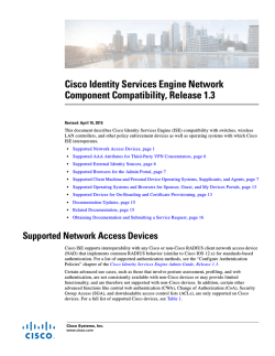
Cisco TrustSec How-To Guide: Cisco ISE Base Configuration and Bootstrapping For Comments, please email: [email protected] Current Document Version: 3.0 August 27, 2012 Table of Contents Table of Contents ............................................................................................................................ 1 Introduction .................................................................................................................................... 3 What Is the Cisco TrustSec System? ............................................................................................................................ 3 About the TrustSec How-To Guides ............................................................................................................................. 3 What does it mean to be вЂ�TrustSec Certified’? ............................................................................................................. 4 Initial Installation and Setup ........................................................................................................... 5 Overview................................................................................................................................................................................. 5 Cisco ISE Installation and Setup ........................................................................................................................................ 5 ISE Web GUI Access ........................................................................................................................ 8 Overview................................................................................................................................................................................. 8 Log In Using the Web-Based Interface ........................................................................................................................... 8 Certificates and Certificate Authorities .......................................................................................... 9 Overview................................................................................................................................................................................. 9 Cisco ISE Configuration – Certificates and Trusting the CA .................................................................................. 9 Add Network Devices .................................................................................................................... 17 Overview.............................................................................................................................................................................. 17 Cisco ISE Configuration – Add Network Devices ......................................................................................................17 Device Profiling ............................................................................................................................. 21 Overview.............................................................................................................................................................................. 21 ISE Configuration – Enable Device Profiling Probes ..............................................................................................21 Appendix A: References ............................................................................................................... 27 Cisco TrustSec System: .................................................................................................................................................. 27 Device Configuration Guides: ...................................................................................................................................... 27 How-To Guide-04-ISE Bootstrapping 2 Introduction What Is the Cisco TrustSec System? Cisco TrustSecВ®, a core component of the Cisco SecureX Architectureв„ў, is an intelligent access control solution. Cisco TrustSec mitigates security risks by providing comprehensive visibility into who and what is connecting across the entire network infrastructure, and exceptional control over what and where they can go. TrustSec builds on your existing identity-aware access layer infrastructure (switches, wireless controllers, and so on). The solution and all the components within the solution are thoroughly vetted and rigorously tested as an integrated system. In addition to combining standards-based identity and enforcement models, such as IEEE 802.1X and VLAN control, the Cisco TrustSec system it also includes advanced identity and enforcement capabilities such as flexible authentication, Downloadable Access Control Lists (dACLs), Security Group Tagging (SGT), device profiling, posture assessments, and more. Figure 1: Cisco TrustSec Architecture Overview RADIUS Guest Services Posture Profiler Ingress Enforcement Wireless user SXP Wired user y rit ag cu T Se oup Gr Campus Network MACsec Ingress Enforcement S Gr ec ou uri p ty Ta g Data Center Egress Enforcement About the TrustSec How-To Guides The TrustSec team is producing this series of How-To documents to describe best practices for Cisco TrustSec deployments. The documents in the series build on one another and guide the reader through a successful implementation of the Cisco TrustSec system. You can use these documents to follow the prescribed path to deploy the entire system, or simply pick the single use-case that meets your specific need. Each guide is this series comes with a subway-style “You Are Here” map to help you identify the stage the document addresses and pinpoint where you are in the Cisco TrustSec deployment process (Figure 2). Figure 2: How-To Guide Navigation Map How-To Guide-04-ISE Bootstrapping 3 What does it mean to be вЂ�TrustSec Certified’? Each TrustSec version number (for example, Cisco TrustSec Version 2.0, Version 2.1, and so on) is a certified design or architecture. All the technology making up the architecture has undergone thorough architectural design development and lab testing. For a How-To Guide to be marked “TrustSec certified,” all the elements discussed in the document must meet the following criteria: п‚· п‚· п‚· Products incorporated in the design must be generally available. Deployment, operation, and management of components within the system must exhibit repeatable processes. All configurations and products used in the design must have been fully tested as an integrated solution. Many features may exist that could benefit your deployment, but if they were not part of the tested solution, they will not be marked as “Cisco TrustSec “certified”. The Cisco TrustSec team strives to provide regular updates to these documents that will include new features as they become available, and are integrated into the Cisco TrustSec test plans, pilot deployments, and system revisions. (i.e., Cisco TrustSec 2.2 certification). Additionally, many features and scenarios have been tested, but are not considered a best practice, and therefore are not included in these documents. As an example, certain IEEE 802.1X timers and local web authentication features are not included. Note: Within this document, we describe the recommended method of deployment, and a few different options depending on the level of security needed in your environment. These methods are examples and step-by-step instructions for Cisco TrustSec deployment as prescribed by Cisco best practices to help ensure a successful project deployment. How-To Guide-04-ISE Bootstrapping 4 Initial Installation and Setup Overview This guide describes running the Cisco Identity Services Engine (ISE) Setup program to configure the Cisco ISE hardware appliances and virtual machine environments. While Cisco ISE comes preinstalled when ordered on a physical appliance, there are times when a physical appliance may need to be reinstalled (or reimaged). This How-To Guide can be used as a reference; we will demonstrate the step-by-step configuration in a later section. Cisco ISE Installation and Setup Procedure 1 Complete the Setup Dialog Note: ISE will need to be freshly installed on the virtual machine. Installation consists of 1) booting from the ISE ISO image and 2) starting the installation process that installs the operating system and ISE application. For details on how to set up VMware, please refer to Installing the Cisco ISE System Software on a VMware Virtual Machine in the Cisco Identity Services Engine Hardware Installation Guide. Note: After these two steps, the installation pauses and a setup dialog must be completed before the installation resumes and completes. Log in to the ise-1 virtual machine console. ********************************************** Please type вЂ�setup’ to configure the appliance ********************************************** localhost login: Enter setup at the login prompt to start the setup dialog. Enter hostname[]: ise Enter IP address []: 10.1.100.21 Enter IP default netmask[]: 255.255.255.0 Enter IP default gateway[]: 10.1.100.1 Enter default DNS domain[]: demo.local Enter Primary nameserver[]: 10.1.100.10 Add/Edit another nameserver? Y/N : n Enter Primary NTP server[time.nist.gov]: ntp.demo.local Add/Edit secondary NTP server? Y/N : n Enter system timezone[UTC]: <return> Enter username[admin]: <return> Enter password: default1A Enter password again: default1A Bringing up network interface... Pinging the gateway... Pinging the primary nameserver ... Do not use вЂ�Ctrl-C’ from this point on... Appliance is configured Installing applications... Installing ise ... Generating configuration... === Initial Setup for Application: ise === Welcome to the ISE initial setup. The purpose of this setup is to provision the the internal ISE database. This setup is non-interactive, and will take roughly 15 minutes to complete. Please be patient. Running database cloning script... Running database network config assistant tool... Extracting ISE database content... Starting ISE database processes... Restarting ISE database processes... Creating ISE M&T session directory... Performing ISE database priming... Generating configuration... Rebooting... How-To Guide-04-ISE Bootstrapping 5 Note: The password policy is not explicitly stated, but a password of default1A will work. Note: After completing the setup dialog, it may take roughly 45 minutes before the installation completes. Note: It's preferred (but not required) to use all lower cases for host name and DNS domain name. Limit the host name to 15 characters if you are planning to join this ISE to an Active Directory domain. After the setup dialog is completed, the installation will continue and finish with a reboot. The installation is complete when you are presented with the following login prompt: ise-1 login: Procedure 2 Complete an ISE Installation Log in using the credentials you provided during the setup. Note: You may continue using the VM console interface to access the ISE CLI, or you may use Secure Shell (SSH) Protocol. On a physical appliance, the serial port or the keyboard and video may be used to access the ISE CLI. Enter show run to confirm the setup settings. Configure a repository. An ISE repository is a file storage location that can be used for copying files to and from ISE. You can use these repositories for various operations, such as patching or upgrading the ISE, backing up or restoring configuration, and creating a support bundle. The different repository types are shown in Table 1. Table 1 ISE Repository Types ISE Repository Types cdrom: (read only) ftp: http: (read only) https: (read only) nfs: Configure an FTP repository on ISE. ise-1/admin# config t Enter configuration commands, one per line. End with CNTL/Z. ise-1/admin(config)# repository myFTP ise-1/admin(config-Repository)# url ftp ftp.demo.local/ ise-1/admin(config-Repository)# user anonymous password plain [email protected] ise-1/admin(config-Repository)# end ise-1/admin# copy running-config startup-config Generating configuration... ise-1/admin# Confirm that ISE can communicate with the repository using the show repository command. (You should see a directory listing from the FTP server.) ise-1/admin# show repository myFTP <file list> ise-1/admin# Note: For this sample setup, the FTP server is on the admin PC and the FTP home directory is C:\Configs. Confirm that time synchronization is working. Immediately after the primary Network Time Protocol (NTP) server is configured, you will see that ISE is in an unsynchronized state. How-To Guide-04-ISE Bootstrapping 6 ise-pap-1/admin# sho ntp Primary NTP : ntp.demo.local unsynchronized time server re-starting polling server every 64 s remote refid st t when poll reach delay offset jitter ============================================================================== 127.127.1.0 .LOCL. 10 l 14 64 7 0.000 0.000 0.001 128.107.220.1 CHU_AUDIO(1) 4 u 14 64 7 0.773 0.528 0.431 Warning: Output results may conflict during periods of changing synchronization. After a few minutes, ISE should synchronize with the primary NTP server. The asterisk indicates which time server it has synchronized with. ise-pap-1/admin# sho ntp Primary NTP : ntp.demo.local synchronised to NTP server (128.107.220.1) at stratum 5 time correct to within 459 ms polling server every 64 s remote refid st t when poll reach delay offset jitter ============================================================================== 127.127.1.0 .LOCL. 10 l 48 64 377 0.000 0.000 0.001 *128.107.220.1 CHU_AUDIO(1) 4 u 45 64 377 0.733 1.738 1.010 Warning: Output results may conflict during periods of changing synchronization. If you see that ISE has synchronized to the local machine (as shown below), this means that NTP time synchronization is not working. ise-pap-1/admin# show ntp Primary NTP : ntp.demo.local synchronised to local net at stratum 11 time correct to within 10 ms polling server every 1024 s remote refid st t when poll reach delay offset jitter ============================================================================== *127.127.1.0 .LOCL. 10 l 5 64 377 0.000 0.000 0.001 128.107.220.1 .LOCL. 4 u 1026 1024 377 0.478 -866.81 60.476 Warning: Output results may conflict during periods of changing synchronization. Note: Synchronization with the NTP server may not be immediate. You may need to wait 10 to 15 minutes for ISE to select the NTP server over the local clock. How-To Guide-04-ISE Bootstrapping 7 ISE Web GUI Access Overview When you log in to the Cisco ISE web-based interface for the first time, you will be using the preinstalled evaluation license. You must use only the supported HTTPS-enabled browsers listed in the previous section. After you have installed Cisco ISE as described in this guide, you can log in to the Cisco ISE web-based interface. Log In Using the Web-Based Interface Procedure 1 Start a Web Session with ISE Open an HTTP-enabled browser window and browse to http://ise.demo.local. Note: This URL was based on lab setup in the previous section. Please use http://<host name>.<domain name> to access the browsers. The HTTPS-enabled browsers are: Mozilla Firefox 2.6 and 9 and Microsoft Internet Explorer 8 and 9. The session will be redirected to the secure Cisco ISE login page: https://ise.demo.local/admin. On the login page, enter the username and password that you defined during setup. Click Login, and the Cisco ISE dashboard appears. Note: The default web UI credentials are admin/cisco. On first login, you will be prompted to change the default password. Figure 3 ISE Web Login How-To Guide-04-ISE Bootstrapping 8 Certificates and Certificate Authorities Overview This guide demonstrates how to generate an ISE certificate, how the certificate authority (CA) issues a certificate to ISE, and how to install the certificates to ISE. While installing Cisco ISE, a default, self-signed certificate will be generated. Although sufficient for labs and demonstrations, it is not a good practice to put Cisco ISE into production with a self-signed certificate. To secure communications with ISE, whether the communication is authentication-related or for ISE management--for example, for configuration using the ISE web interface--X.509 certificates and certificate trust chains need to be configured to enable asymmetric encryption. Note: Time synchronization is extremely important for certificate operations. Ensure that you have configured NTP and have the correct time. Cisco ISE Configuration – Certificates and Trusting the CA Note: For certificate chains: The entire chain should be imported successfully before the certificate request is created. Procedure 1 Request a Certificate from the Certificate Authority. Go to Administrationпѓ System пѓ Certificates пѓ Local Certificates. Click Add пѓ Generate Certificate Signing Request. Figure 4 Generate Certificate Request Enter the fully qualified domain name (FQDN) for the Cisco ISE node into the Certificate Subject field. Note: The example that includes additional fields for public CA are: CN=ise.cts.local, OU=SAMPG, O=Cisco, L=San Jose, ST=California, C=US Click Submit. How-To Guide-04-ISE Bootstrapping 9 Figure 5 Certificate Details Click Certificate Signing Requests and select your new request. Click Export. Figure 6 Export Newly Created Certificate Save the .pem file to an easily accessible location. Figure 7 Saving .pem File Procedure 2 Download the CA Root Certificate and Issue a Certificate Browse to your CA. Click the link titled “Download a CA certificate, certificate chain, or CRL.” How-To Guide-04-ISE Bootstrapping 10 Note: We are using a Microsoft CA; therefore, we are browsing to http://ad.cts.local/certsrv/. Depending on the CA in your organization, the certificate request will follow a different procedure. When using the Microsoft CA, it has been noted that using Internet Explorer will provide a better experience. Figure 8 Download a CA Certificate Click Download CA certificate. Figure 9 Select Certificate and Encoding Method Save the resulting .cer file in a location that can be easily accessed. Cisco Best Practice: Name the file something unique, such as RootCert.cer. Click Home, in the upper right corner. Click Request a certificate. How-To Guide-04-ISE Bootstrapping 11 Figure 10 Request a Certificate Click advanced certificate request. Figure 11 Advanced Certificate Request Select the option titled “Submit a certificate request by using a base-64-encoded CMC or PKCS #10 file, or submit a renewal request by using a base-64-encoder PKCS #7 file.” Figure 12 Select the Certificate Request Option Using NotePad or another text editor, open the .pem file saved in Procedure 2. Highlight the entire contents of the file and select Edit пѓ Copy. How-To Guide-04-ISE Bootstrapping 12 Figure 13 Copy the Certificate Paste the contents from the certificate request .pem file into the Saved Request text box in the CA window. The Certificate Template should be set to Web Server. Figure 14 Submit a Certificate Request In the Cisco ISE administrative interface, navigate to Administration пѓ System пѓ Certificates пѓ Certificate Authority Certificates. Click Import. How-To Guide-04-ISE Bootstrapping 13 Figure 15 Import the Certificate Browse for the CA root certificate saved in Procedure 3, Step 3. Select the checkbox titled “Trust for client authentication,” and then the box titled “Enable Validation of Certificate Extensions.” Figure 16 Trust with EAP-TLS Click Submit. Procedure 3 Install the New Local Certificate Now that the CA root certificate is trusted, it is time to replace the self-signed certificate with the CA-issued certificate, and delete the completed certificate-signing request (CSR). From Administration пѓ System пѓ Certificates пѓ Local Certificates, click Add пѓ Bind CA Certificate. How-To Guide-04-ISE Bootstrapping 14 Figure 17 Bind CA Certificate Browse for the certificate issued by the CA for Cisco ISE. Select the EAP and Management Interface checkboxes. Click Submit. Figure 18 Bind CA Signed Certificate Selection Note: If you did not create the certificate signing request (CSR) with the same host name as the Cisco ISE server (or did not use the same domain name), then you will receive an error message. Delete the old CSR or simply change the host name and start again. Procedure 4 Clean Up Old Certificates and CSRs Select the checkbox titled “Default self-signed server certificate.” Click Delete. How-To Guide-04-ISE Bootstrapping 15 Figure 19 Delete Old Certificate Click Certificate Signing Requests. Select the CSR. Click Delete. Figure 20 Delete Old Signing Request How-To Guide-04-ISE Bootstrapping 16 Add Network Devices Overview Any switch or Wireless LAN Controller (WLC) that may be sending RADIUS requests to Cisco ISE to authenticate and authorize network clients should be added to Cisco ISE. Cisco ISE provides a default device that may be configured to allow any network device to send RADIUS requests, but it is not a good security practice to use this feature. In order to provide a thorough level of policy creation, as well as detailed levels of reporting, it is recommended to add all devices individually to Cisco ISE and to use network device groups (NDGs) to organize those network devices. Note: For bulk import of network devices and assignment of those devices to their respective NDGs, Cisco ISE provides an import/export mechanism. See the Cisco ISE User Guide (http://www.cisco.com/en/US/docs/security/ise/1.1/user_guide/ise_admin.html) for more detailed instructions. Cisco ISE Configuration – Add Network Devices Procedure 1 Configure Network Device Groups NDGs are powerful tools when used appropriately. Cisco ISE has the power to use any number of attributes when it makes policy decisions. NDG membership is one such attribute that can be used as a policy condition. An example could be the creation of an NDG for switches, another for VPN devices, and a third group for WLCs. Cisco Best Practice: At a minimum, always use NDGs for device types and location. Go to Administration пѓ Network Resource пѓ Network Device Groups. By default there are two top-level NDG types: All Device Types and All Locations. These types are a good start for most deployments. Your deployment may need to create multiple location sub-groups. The possibilities are virtually limitless (see the sample hierarchy that follows). The group structure is hierarchical. With an example group structure of: All Locations пѓ North America пѓ US пѓ SJC пѓ Building M пѓ 1st Floor, you can use any level of the group hierarchy in your policy. In other words, you can select “US” in your policy and get every device in every group underneath “US.” Figure 21 Network Device Groups Select Network Devices. Click Add. How-To Guide-04-ISE Bootstrapping 17 Figure 22 Add Network Devices Enter the name Switch in the Name field and click Submit. Figure 23 Add a Switch Repeat the process to create your desired NDG hierarchy. Figure 24 depicts an example hierarchy. Figure 24 Group Types How-To Guide-04-ISE Bootstrapping 18 Procedure 2 Add Network Device Go to Administration пѓ Network Resources пѓ Network Devices and click Add. Figure 25 Network Devices Fill out the Name, IP Address, and Network Device Group fields. Figure 26 Network Device Details Repeat for all network devices (also known as “policy enforcement points”). Note: For bulk administration, network devices may be imported via CSV file. See the Cisco ISE User Guide (http://www.cisco.com/en/US/docs/security/ise/1.1/user_guide/ise_admin.html) for more information. Table 2 Network Devices Section Purpose General Settings Name Use a name that is easy to distinguish later. The name will display in all monitoring, dashboards, and reporting. Description Optional IP Address Must match the source interface chosen for RADIUS communication in the switch configuration section. Best practice is to use How-To Guide-04-ISE Bootstrapping 19 Section Purpose loopback interfaces for management. Optional Optional Model Name Software Version Network Device Group Location Be as specific as possible. Device Type Be as specific as possible. Authentication Settings Protocol Will be prepopulated as RADIUS. Shared Secret Must match the RADIUS key configured on the switch. SNMP Settings (used for device profiling) SNMP Version Select the version in use in your organization. SNMP RO SNMP is used only for device profiling purposes. Community Cisco ISE will probe the switch for contents of Cisco Discovery Protocol tables, Link Layer Discovery Protocol (LLDP) tables, and more. SNMP Used with SNMPv3 – must match the Username configuration on the switch. Security Level Used with SNMPv3 – must match the configuration on the switch. Auth Protocol Used with SNMPv3 – must match the configuration on the switch. Privacy Used with SNMPv3 – must match the Protocol configuration on the switch. Polling It is not recommended to change the default Interval polling interval: 3,600 sec Link Trap Configures Cisco ISE to accept linkup and Query linkdown SNMP traps from the switch. Leave this checkbox selected. MAC Trap Configures Cisco ISE to accept mac-address-table Query type traps from the switch. Leave this checkbox selected. Security Group Access (SGA): Not used at this stage of our deployment guide. This will be revisited in the SGA section. Device Configuration Deployment: Not used at this stage of our deployment guide. This will be revisited in the SGA section. How-To Guide-04-ISE Bootstrapping 20 Device Profiling Overview The Cisco ISE Profiler is responsible for endpoint detection and classification on the ISE platform. It uses an array of probes (sensors) that collect attributes about an endpoint and a policy-based mechanism that evaluates the attributes to match the endpoint with a predefined profile. The result of the collection and classification from the profiler are then used as conditions in the authentication and authorization policies. The classification result of profiling can be used to invoke a different authorization result. Note: Please see the How-To-30-Profiling_Design_Guide for more details on the probes. Figure 27 depicts an example of a differentiated device policy based on profiling. Figure 27 Device Policy Based on Profiling Users, using the same SSID, can be associated to different wired VLAN interfaces after EAP authentication. п‚· Employees using corporate laptops with their AD user ID assigned to VLAN 30 = full network access п‚· Employees using personal iPads/iPhones with their AD user ID assigned to VLAN 40 = Internet only ISE Configuration – Enable Device Profiling Probes At this stage we will enable profiling probes on the Cisco ISE device. In a distributed deployment, profiling probes would generally be enabled on all the Policy Services Nodes (PSNs), sometimes referred to as Policy Decision Points or PDPs. The specifics of which probes to enable (and where to enable them) can be complex and should be addressed in the high-level design process. Note: This guide will not explain how to enable a NetFlow probe. NetFlow is a powerful tool, but its implementation must be thought out carefully. In certain Cisco TrustSec implementations, NetFlow will be crucial. However, an important aspect of NetFlow is understanding what data to send from the infrastructure. This configuration is out of the scope of this guide, but will be in either a specific follow-on guide or in a future version of a Cisco TrustSec implementation guide. Procedure 1 Enable the Profiling Probes Navigate to Administration пѓ System пѓ Deployment. Select the Policy Services Node. This node may be a single Cisco ISE node, as depicted in Figure 28. If your Cisco TrustSec deployment is distributed, you should select one of the nodes configured for policy service. Repeat these steps for each PSN in the deployment. How-To Guide-04-ISE Bootstrapping 21 Check Enable Session Service. Figure 28 Select the Policy Services Node Click the Profiling Configuration tab. Figure 29 Profiling Configuration Enable the checkbox for DHCP. This is the DHCP IP Helper probe. It will listen to packets forwarded to it from the DHCP IP Helper configured on the switch or other Layer 3 device. The DHCP IP Helper probe will listen to traffic from the DHCP client to server only (DHCPDISCOVER and DHCPREQUEST). Enable this probe on a particular interface or on all interfaces. How-To Guide-04-ISE Bootstrapping 22 Figure 30 Enable DHCP Enable the checkbox for DHCPSPAN. The DHCP Span probe will listen to packets forwarded to it from the switchport analyzer (SPAN) session configured on the switch. This probe will listen to all of the DHCP traffic. Figure 31 Enable DHCPPSAN When a switchport is configured to be a SPAN destination, the port no longer functions normally. The interface connected to the SPAN destination port is expected to be in “promiscuous mode,” meaning the interface is expected to be capturing all traffic that enters the port, and will not respond to directed communications. With that understanding, it is recommended that one or more of the Cisco ISE server interfaces be set to promiscuous mode for the DHCPSPAN and HTTP probes. In this guide, we will dedicate the GigabitEthernet 1 interface to be a SPAN destination. Note: When using an interface on the Cisco ISE other than GigabitEthernet 0, enter the CLI and type no shutdown at interface configuration mode to enable the interface. Please see the “Add Network Devices” procedure for the switch configuration. To configure the SPAN (monitor session) on the switchport, please see the “Configure the SPAN Session on the Switch” procedure. Enable the checkbox for HTTP. Figure 32 Enable HTTP The HTTP Span probe will listen for HTTP packets on the specified interface and parse them to augment endpoints with HTTP attributes. The HTTP probe will capture traffic emanating from the endpoint and going to port 80 to detect what user agent and other HTTP attributes are present within the HTTP request. The HTTP data is important for, among other things, mobile device recognition. Use of HTTP will also require some design consideration and should be a part of the High-Level Design. How-To Guide-04-ISE Bootstrapping 23 Enable the checkbox for RADIUS. The RADIUS probe will help detect endpoints based on RADIUS information. It is also used to receive profiling data from the device sensors in Cisco IOS routers and WLCs. Figure 33 Enable RADIUS Table 3 lists known attributes collected by the RADIUS probe. The RADIUS probe helps detect endpoints based on RADIUS information. Table 3 Attributes Collected by RADIUS Probe User-Name NAS-IP Address NAS-Port Framed-IP-Address Calling-Station-ID Acct-Session-ID Acct-Session-Time Acct-Terminate-Cause Note: The RADIUS probe may also trigger DNS and SNMP Query collection events (if enabled). Enable the checkbox for DNS. The DNS probe in your Cisco ISE deployment allows the profiler to look up an endpoint and get the fully qualified domain name (FQDN) of that endpoint. Figure 34 Enable DNS A reverse DNS lookup will be completed only when an endpoint detected by the DHCP, RADIUS, HTTP, and SNMP probes contains the respective attributes listed in Table 4. So, for DNS lookup, at least one of the probes listed in Table 4 needs to be enabled along with the DNS probe. Table 4 Probes That Need to Be Enabled Probes That Need to Be Enabled DHCP IP Helper, DHCP Span – “dhcp-requested-address” RADIUS Probe – “Framed-IP-Address” SNMP Probe – “cdpCacheAddress” HTTP Probe – “Source IP” Enable the checkbox for SNMPQUERY. How-To Guide-04-ISE Bootstrapping 24 Figure 35 Enable SNMPQUERY Note: When you configure SNMP settings on the network devices, you need to also ensure that Cisco Discovery Protocol is enabled on all the ports of the network devices. If you disable Cisco Discovery Protocol on any of these ports, you may not be able to profile properly because you will miss the Cisco Discovery Protocol information about all the connected endpoints. The SNMPQuery probe polls all of the SNMP-enabled network devices at configured polling intervals. This feature requires the configuration of SNMP parameters in the Add Network Device section. The SNMPQuery probe queries the following MIBS: п‚· System п‚· cdpCacheEntry п‚· cLApEntry (If device is WLC) п‚· cldcClientEntry (If device is WLC) LinkUp/MAC Notification/RADIUS Acct Start event queries: п‚· Interface data (ifIndex, ifDesc, etc.) п‚· Port and VLAN data п‚· Session data (if interface type is Ethernet) п‚· Cisco Discovery Protocol data (if the device is a Cisco device) For distributed deployments, NAD polling is distributed among enabled SNMP query probes. Note: SNMPTrap-triggered queries are queued to the same node for SNMP Query probe. If the local SNMP Query probe is not enabled, those queries are dropped. Enable the checkbox for SNMPTRAP. The SNMP Trap receives information from the configured NADs that support MAC notification, linkup, linkdown, and informs. For SNMPTrap to be fully functional, you must also enable the SNMPQuery probe. The SNMPTrap probe receives information from the specific NADs when ports come up or go down and endpoints disconnect or connect to your network. The To make this feature functional, you must configure the NAD to send SNMP traps. Information received from the SNMP traps will not create a new endpoint in Cisco ISE, but can be used for profiling. How-To Guide-04-ISE Bootstrapping 25 Figure 36 Enable SNMPTRAP Note: SNMP informs are supported. Ensure the Link Trap Query and MAC Trap Query options are enabled and click Save. Note: If you use VMware for the profiling, please refer to the ISE Base Configurations How-To Guide. How-To Guide-04-ISE Bootstrapping 26 Appendix A: References Cisco TrustSec System: п‚· http://www.cisco.com/go/trustsec п‚· http://www.cisco.com/en/US/solutions/ns340/ns414/ns742/ns744/landing_DesignZone_TrustSec.html Device Configuration Guides: Cisco Identity Services Engine User Guides: http://www.cisco.com/en/US/products/ps11640/products_user_guide_list.html For more information about Cisco IOS Software, Cisco IOS XE Software, and Cisco NX-OS Software releases, please refer to following URLs: п‚· For Cisco Catalyst 2900 series switches: http://www.cisco.com/en/US/products/ps6406/products_installation_and_configuration_guides_list.html п‚· For Cisco Catalyst 3000 series switches: http://www.cisco.com/en/US/products/ps7077/products_installation_and_configuration_guides_list.html п‚· For Cisco Catalyst 3000-X series switches: http://www.cisco.com/en/US/products/ps10745/products_installation_and_configuration_guides_list.html п‚· For Cisco Catalyst 4500 series switches: http://www.cisco.com/en/US/products/hw/switches/ps4324/products_installation_and_configuration_guides_list.ht ml п‚· For Cisco Catalyst 6500 series switches: http://www.cisco.com/en/US/products/hw/switches/ps708/products_installation_and_configuration_guides_list.html п‚· For Cisco ASR 1000 series routers: http://www.cisco.com/en/US/products/ps9343/products_installation_and_configuration_guides_list.html For Cisco Wireless LAN Controllers: http://www.cisco.com/en/US/docs/wireless/controller/7.0MR1/configuration/guide/wlc_cg70MR1.html How-To Guide-04-ISE Bootstrapping 27
© Copyright 2026 Paperzz