8086 assembler tutorial for beginners (part 1)
This tutorial is intended for those who are not familiar with assembler at all, or
have a very distant idea about it. of course if you have knowledge of some
other programming language (basic, c/c++, pascal...) that may help you a lot.
but even if you are familiar with assembler, it is still a good idea to look
through
this
document
in
order
to
study
emu8086
syntax.
It is assumed that you have some knowledge about number representation
(hex/bin), if not it is highly recommended to study numbering systems
tutorial before you proceed.
what
is
language?
assembly
assembly language is a low
level programming language.
you
need
to
get
some
knowledge about computer
structure
in
order
to
understand
anything.
the
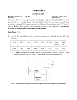
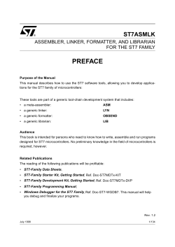
simple computer model as i
see
it:
the system bus (shown in
yellow) connects the various
components of a computer.
the CPU is the heart of the computer, most of computations occur inside the
CPU.
RAM is a place to where the programs are loaded in order to be executed.
inside the cpu
general purpose registers
8086 CPU has 8 general purpose registers, each register has its own name:
п‚·
п‚·
п‚·
п‚·
п‚·
п‚·
п‚·
п‚·
AX - the accumulator register (divided into AH / AL).
BX - the base address register (divided into BH / BL).
CX - the count register (divided into CH / CL).
DX - the data register (divided into DH / DL).
SI - source index register.
DI - destination index register.
BP - base pointer.
SP - stack pointer.
despite the name of a register, it's the programmer who determines the usage
for each general purpose register. the main purpose of a register is to keep a
number (variable). the size of the above registers is 16 bit, it's something like:
0011000000111001b (in binary form), or 12345 in decimal (human) form.
4 general purpose registers (AX, BX, CX, DX) are made of two separate 8 bit
registers, for example if AX= 0011000000111001b, then AH=00110000b
and AL=00111001b. therefore, when you modify any of the 8 bit registers 16
bit register is also updated, and vice-versa. the same is for other 3 registers,
"H" is for high and "L" is for low part.
because registers are located inside the CPU, they are much faster than
memory. Accessing a memory location requires the use of a system bus, so it
takes much longer. Accessing data in a register usually takes no time.
therefore, you should try to keep variables in the registers. register sets are
very small and most registers have special purposes which limit their use as
variables, but they are still an excellent place to store temporary data of
calculations.
segment registers
п‚·
п‚·
п‚·
п‚·
CS - points at the segment containing the current program.
DS - generally points at segment where variables are defined.
ES - extra segment register, it's up to a coder to define its usage.
SS - points at the segment containing the stack.
although it is possible to store any data in the segment registers, this is never
a good idea. the segment registers have a very special purpose - pointing at
accessible blocks of memory.
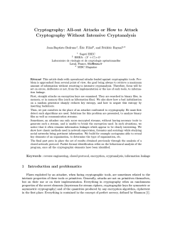
segment registers work together with general purpose register to access any
memory value. For example if we would like to access memory at the physical
address 12345h (hexadecimal), we should set the DS = 1230h and SI =
0045h. This is good, since this way we can access much more memory than
with a single register that is limited to 16 bit values.
CPU makes a calculation of physical address by multiplying the segment
register by 10h and adding general purpose register to it (1230h * 10h + 45h
= 12345h):
the address formed with 2 registers is called an effective address.
by default BX, SI and DI registers work with DS segment register;
BP and SP work with SS segment register.
other general purpose registers cannot form an effective address!
also, although BX can form an effective address, BH and BL cannot.
special purpose registers
п‚·
п‚·
IP - the instruction pointer.
flags register - determines the current state of the microprocessor.
IP register always works together with CS segment register and it points to
currently executing instruction.
flags register is modified automatically by CPU after mathematical
operations, this allows to determine the type of the result, and to determine
conditions to transfer control to other parts of the program.
generally you cannot access these registers directly, the way you can access
AX and other general registers, but it is possible to change values of system
registers using some tricks that you will learn a little bit later.
Memory Access
to access memory we can use these four registers: BX, SI, DI, BP. combining
these registers inside [ ] symbols, we can get different memory locations.
these combinations are supported (addressing modes):
[BX + SI]
[BX + DI]
[BP + SI]
[BP + DI]
[SI]
[DI]
d16 (variable offset only)
[BX]
[BX + SI + d8]
[BX + DI + d8]
[BP + SI + d8]
[BP + DI + d8]
[SI + d8]
[DI + d8]
[BP + d8]
[BX + d8]
[BX + SI + d16]
[BX + DI + d16]
[BP + SI + d16]
[BP + DI + d16]
[SI + d16]
[DI + d16]
[BP + d16]
[BX + d16]
d8 - stays for 8 bit signed immediate displacement (for example: 22, 55h, -1,
etc...)
d16 - stays for 16 bit signed immediate displacement (for example: 300,
5517h, -259, etc...).
displacement can be a immediate value or offset of a variable, or even both. if
there are several values, assembler evaluates all values and calculates a single
immediate value..
displacement can be inside or outside of the [ ] symbols, assembler generates
the same machine code for both ways.
displacement is a signed value, so it can be both positive or negative.
generally the compiler takes care about difference between d8 and d16, and
generates the required machine code.
for example, let's assume that DS = 100, BX = 30, SI = 70.
The following addressing mode: [BX + SI] + 25
is calculated by processor to this physical address: 100 * 16 + 30 + 70 + 25
= 1725.
by default DS segment register is used for all modes except those with BP
register, for these SS segment register is used.
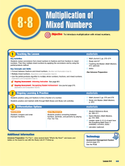
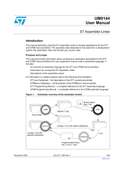
there is an easy way to remember all those possible combinations using this
chart:
you can form all valid combinations by taking only one item from each column
or skipping the column by not taking anything from it. as you see BX and BP
never go together. SI and DI also don't go together. here are an examples of
a valid addressing modes:
[BX+5]
,
[BX+SI]
,
[DI+BX-4]
the value in segment register (CS, DS, SS, ES) is called a segment,
and the value in purpose register (BX, SI, DI, BP) is called an offset.
When DS contains value 1234h and SI contains the value 7890h it can be
also recorded as 1234:7890. The physical address will be 1234h * 10h +
7890h = 19BD0h.
if zero is added to a decimal number it is multiplied by 10, however 10h = 16,
so if zero is added to a hexadecimal value, it is multiplied by 16, for example:
7h = 7
70h = 112
in order to say the compiler about data type,
these prefixes should be used:
byte ptr - for byte.
word ptr - for word (two bytes).
for example:
byte ptr [BX] ; byte access.
or
word ptr [BX] ; word access.
assembler supports shorter prefixes as well:
b. - for byte ptr
w. - for word ptr
in certain cases the assembler can calculate the data type automatically.
MOV instruction
п‚·
copies the second operand (source) to the first operand (destination).
п‚·
the source operand can be an immediate value, general-purpose register
or memory location.
п‚·
the destination register can be a general-purpose register, or memory
location.
п‚·
both operands must be the same size, which can be a byte or a word.
these types of operands are supported:
MOV REG, memory
MOV memory, REG
MOV REG, REG
MOV memory, immediate
MOV REG, immediate
REG: AX, BX, CX, DX, AH, AL, BL, BH, CH, CL, DH, DL, DI, SI, BP, SP.
memory: [BX], [BX+SI+7], variable, etc...
immediate: 5, -24, 3Fh, 10001101b, etc...
for segment registers only these types of MOV are supported:
MOV SREG, memory
MOV memory, SREG
MOV REG, SREG
MOV SREG, REG
SREG: DS, ES, SS, and only as second operand: CS.
REG: AX, BX, CX, DX, AH, AL, BL, BH, CH, CL, DH, DL, DI, SI, BP, SP.
memory: [BX], [BX+SI+7], variable, etc...
The MOV instruction cannot be used to set the value of the CS and IP
registers.
here is a short program that demonstrates the use of MOV instruction:
ORG 100h
; this directive required for a simple 1 segment .com program.
MOV AX, 0B800h ; set AX to hexadecimal value of B800h.
MOV DS, AX
; copy value of AX to DS.
MOV CL, 'A'
; set CL to ASCII code of 'A', it is 41h.
MOV CH, 1101_1111b ; set CH to binary value.
MOV BX, 15Eh
; set BX to 15Eh.
MOV [BX], CX
; copy contents of CX to memory at B800:015E
RET
; returns to operating system.
you can copy & paste the above program to emu8086 code editor, and press
[Compile and Emulate] button (or press F5 key on your keyboard).
the emulator window should open with this program loaded, click [Single
Step] button and watch the register values.
how to do copy & paste:
1. select the above text using mouse, click before the text and drag it down
until everything is selected.
2. press Ctrl + C combination to copy.
3. go to emu8086 source editor and press Ctrl + V combination to paste.
as you may guess, ";" is used for comments, anything after ";" symbol is
ignored by compiler.
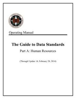
you should see something like that when program finishes:
actually the above program writes directly to video memory, so you may see
that MOV is a very powerful instruction
Variables
Variable is a memory location. For a programmer it is much easier to have
some value be kept in a variable named "var1" then at the address
5A73:235B, especially when you have 10 or more variables.
Our compiler supports two types of variables: BYTE and WORD.
Syntax for a variable declaration:
name DB value
name DW value
DB - stays for Define Byte.
DW - stays for Define Word.
name - can be any letter or digit combination, though it should start with a letter. It's possible
to declare unnamed variables by not specifying the name (this variable will have an address
but no name).
value - can be any numeric value in any supported numbering system (hexadecimal, binary, or
decimal), or "?" symbol for variables that are not initialized.
As you probably know from part 2 of this tutorial, MOV instruction is used to
copy values from source to destination.
Let's see another example with MOV instruction:
ORG 100h
MOV AL, var1
MOV BX, var2
RET
; stops the program.
VAR1 DB 7
var2 DW 1234h
Copy the above code to emu8086 source editor, and press F5 key to compile
and load it in the emulator. You should get something like:
As you see this looks a lot like our example, except that variables are replaced
with actual memory locations. When compiler makes machine code, it
automatically replaces all variable names with their offsets. By default
segment is loaded in DS register (when COM files is loaded the value of DS
register is set to the same value as CS register - code segment).
In memory list first row is an offset, second row is a hexadecimal value,
third row is decimal value, and last row is an ASCII character value.
Compiler is not case sensitive, so "VAR1" and "var1" refer to the same
variable.
The offset of VAR1 is 0108h, and full address is 0B56:0108.
The offset of var2 is 0109h, and full address is 0B56:0109, this variable is a
WORD so it occupies 2 BYTES. It is assumed that low byte is stored at lower
address, so 34h is located before 12h.
You can see that there are some other instructions after the RET instruction,
this happens because disassembler has no idea about where the data starts, it
just processes the values in memory and it understands them as valid 8086
instructions (we will learn them later).
You can even write the same program using DB directive only:
ORG 100h ; just a directive to make a simple .com file
(expands into no code).
DB 0A0h
DB 08h
DB 01h
DB 8Bh
DB 1Eh
DB 09h
DB 01h
DB 0C3h
DB 7
DB 34h
DB 12h
Copy the above code to emu8086 source editor, and press F5 key to compile
and load it in the emulator. You should get the same disassembled code, and
the same functionality!
As you may guess, the compiler just converts the program source to the set of
bytes, this set is called machine code, processor understands the machine
code and executes it.
ORG 100h is a compiler directive (it tells compiler how to handle the source
code). This directive is very important when you work with variables. It tells
compiler that the executable file will be loaded at the offset of 100h (256
bytes), so compiler should calculate the correct address for all variables when
it replaces the variable names with their offsets. Directives are never
converted to any real machine code.
Why executable file is loaded at offset of 100h? Operating system keeps
some data about the program in the first 256 bytes of the CS (code segment),
such as command line parameters and etc.
Though this is true for COM files only, EXE files are loaded at offset of 0000,
and generally use special segment for variables. Maybe we'll talk more about
EXE files later.
Arrays
Arrays can be seen as chains of variables. A text string is an example of a byte
array, each character is presented as an ASCII code value (0..255).
Here are some array definition examples:
a DB 48h, 65h, 6Ch, 6Ch, 6Fh, 00h
b DB 'Hello', 0
b is an exact copy of the a array, when compiler sees a string inside quotes it
automatically converts it to set of bytes. This chart shows a part of the
memory where these arrays are declared:
You can access the value of any element in array using square brackets, for
example:
MOV AL, a[3]
You can also use any of the memory index registers BX, SI, DI, BP, for
example:
MOV SI, 3
MOV AL, a[SI]
If you need to declare a large array you can use DUP operator.
The syntax for DUP:
number DUP ( value(s) )
number - number of duplicate to make (any constant value).
value - expression that DUP will duplicate.
for example:
c DB 5 DUP(9)
is an alternative way of declaring:
c DB 9, 9, 9, 9, 9
one more example:
d DB 5 DUP(1, 2)
is an alternative way of declaring:
d DB 1, 2, 1, 2, 1, 2, 1, 2, 1, 2
Of course, you can use DW instead of DB if it's required to keep values larger
then 255, or smaller then -128. DW cannot be used to declare strings.
Getting the Address of a Variable
There is LEA (Load Effective Address) instruction and alternative OFFSET
operator. Both OFFSET and LEA can be used to get the offset address of the
variable.
LEA is more powerful because it also allows you to get the address of an
indexed variables. Getting the address of the variable can be very useful in
some situations, for example when you need to pass parameters to a
procedure.
Reminder:
In order to tell the compiler about data type,
these prefixes should be used:
BYTE PTR - for byte.
WORD PTR - for word (two bytes).
For example:
BYTE PTR [BX] ; byte access.
or
WORD PTR [BX] ; word access.
emu8086 supports shorter prefixes as well:
b. - for BYTE PTR
w. - for WORD PTR
in certain cases the assembler can calculate the data type automatically.
Here is first example:
ORG 100h
MOV AL, VAR1
moving it to AL.
LEA
BX, VAR1
; check value of VAR1 by
; get address of VAR1 in BX.
MOV BYTE PTR [BX], 44h ; modify the contents of
VAR1.
MOV AL, VAR1
moving it to AL.
; check value of VAR1 by
RET
VAR1 DB 22h
END
Here is another example, that uses OFFSET instead of LEA:
ORG 100h
MOV AL, VAR1
moving it to AL.
; check value of VAR1 by
MOV BX, OFFSET VAR1
in BX.
; get address of VAR1
MOV BYTE PTR [BX], 44h ; modify the contents of
VAR1.
MOV AL, VAR1
moving it to AL.
; check value of VAR1 by
RET
VAR1 DB 22h
END
Both examples have the same functionality.
These lines:
LEA BX, VAR1
MOV BX, OFFSET VAR1
are even compiled into the same machine code: MOV BX, num
num is a 16 bit value of the variable offset.
Please note that only these registers can be used inside square brackets (as
memory pointers): BX, SI, DI, BP!
(see previous part of the tutorial).
Constants
Constants are just like variables, but they exist only until your program is
compiled (assembled). After definition of a constant its value cannot be
changed. To define constants EQU directive is used:
name EQU < any expression >
For example:
k EQU 5
MOV AX, k
The above example is functionally identical to code:
MOV AX, 5
You can view variables while your program executes by selecting "Variables"
from the "View" menu of emulator.
To view arrays you should click on a variable and set Elements property to
array size. In assembly language there are not strict data types, so any
variable can be presented as an array.
Variable can be viewed in any numbering system:
п‚·
п‚·
п‚·
п‚·
п‚·
п‚·
HEX - hexadecimal (base 16).
BIN - binary (base 2).
OCT - octal (base 8).
SIGNED - signed decimal (base 10).
UNSIGNED - unsigned decimal (base 10).
CHAR - ASCII char code (there are 256 symbols, some symbols are
invisible).
You can edit a variable's value when your program is running, simply double
click it, or select it and click Edit button.
It is possible to enter numbers in any system, hexadecimal numbers should
have "h" suffix, binary "b" suffix, octal "o" suffix, decimal numbers require no
suffix. String can be entered this way:
'hello world', 0
(this string is zero terminated).
Arrays may be entered this way:
1, 2, 3, 4, 5
(the array can be array of bytes or words, it depends whether BYTE or WORD
is selected for edited variable).
Expressions are automatically converted, for example:
when this expression is entered:
5+2
it will be converted to 7 etc...
Interrupts
Interrupts can be seen as a number of functions. These functions make the
programming much easier, instead of writing a code to print a character you
can simply call the interrupt and it will do everything for you. There are also
interrupt functions that work with disk drive and other hardware. We call such
functions software interrupts.
Interrupts are also triggered by different hardware, these are called hardware
interrupts. Currently we are interested in software interrupts only.
To make a software interrupt there is an INT instruction, it has very simple
syntax:
INT value
Where value can be a number between 0 to 255 (or 0 to 0FFh),
generally we will use hexadecimal numbers.
You may think that there are only 256 functions, but that is not correct. Each
interrupt may have sub-functions.
To specify a sub-function AH register should be set before calling interrupt.
Each interrupt may have up to 256 sub-functions (so we get 256 * 256 =
65536 functions). In general AH register is used, but sometimes other
registers maybe in use. Generally other registers are used to pass parameters
and data to sub-function.
The following example uses INT 10h sub-function 0Eh to type a "Hello!"
message. This functions displays a character on the screen, advancing the
cursor and scrolling the screen as necessary.
ORG
100h ; directive to make a simple .com file.
; The sub-function that we are using
; does not modify the AH register on
; return, so we may set it only once.
MOV
AH, 0Eh ; select sub-function.
; INT 10h / 0Eh sub-function
; receives an ASCII code of the
; character that will be printed
; in AL register.
MOV AL, 'H' ; ASCII code: 72
INT 10h
; print it!
MOV AL, 'e' ; ASCII code: 101
INT 10h
; print it!
MOV AL, 'l' ; ASCII code: 108
INT 10h
; print it!
MOV AL, 'l' ; ASCII code: 108
INT 10h
; print it!
MOV AL, 'o' ; ASCII code: 111
INT 10h
; print it!
MOV AL, '!' ; ASCII code: 33
INT 10h
; print it!
RET
; returns to operating system.
Copy & paste the above program to emu8086 source code editor, and press
[Compile and Emulate] button. Run it!
See list of supported interrupts for more information about interrupts.
Library of common functions - emu8086.inc
To make programming easier there are some common functions that can be
included in your program. To make your program use functions defined in
other file you should use the INCLUDE directive followed by a file name.
Compiler automatically searches for the file in the same folder where the
source file is located, and if it cannot find the file there - it searches in Inc
folder.
Currently you may not be able to fully understand the contents of the
emu8086.inc (located in Inc folder), but it's OK, since you only need to
understand what it can do.
To use any of the functions in emu8086.inc you should have the following line
in the beginning of your source file:
include 'emu8086.inc'
emu8086.inc defines the following macros:
п‚·
PUTC char - macro with 1 parameter, prints out an ASCII char at
current cursor position.
п‚·
GOTOXY col, row - macro with 2 parameters, sets cursor position.
п‚·
PRINT string - macro with 1 parameter, prints out a string.
п‚·
PRINTN string - macro with 1 parameter, prints out a string. The same
as PRINT but automatically adds "carriage return" at the end of the
string.
п‚·
CURSOROFF - turns off the text cursor.
п‚·
CURSORON - turns on the text cursor.
To use any of the above macros simply type its name somewhere in your code,
and if required parameters, for example:
include emu8086.inc
ORG
100h
PRINT 'Hello World!'
GOTOXY 10, 5
PUTC 65
PUTC 'B'
RET
END
; 65 - is an ASCII code for 'A'
; return to operating system.
; directive to stop the compiler.
When compiler process your source code it searches the emu8086.inc file for
declarations of the macros and replaces the macro names with real code.
Generally macros are relatively small parts of code, frequent use of a macro
may make your executable too big (procedures are better for size
optimization).
emu8086.inc also defines the following procedures:
п‚·
PRINT_STRING - procedure to print a null terminated string at current
cursor position, receives address of string in DS:SI register. To use it
declare: DEFINE_PRINT_STRING before END directive.
п‚·
PTHIS - procedure to print a null terminated string at current cursor
position (just as PRINT_STRING), but receives address of string from
Stack. The ZERO TERMINATED string should be defined just after the
CALL instruction. For example:
CALL PTHIS
db 'Hello World!', 0
To use it declare: DEFINE_PTHIS before END directive.
п‚·
GET_STRING - procedure to get a null terminated string from a user,
the received string is written to buffer at DS:DI, buffer size should be in
DX. Procedure stops the input when 'Enter' is pressed. To use it declare:
DEFINE_GET_STRING before END directive.
п‚·
CLEAR_SCREEN - procedure to clear the screen, (done by scrolling
entire screen window), and set cursor position to top of it. To use it
declare: DEFINE_CLEAR_SCREEN before END directive.
п‚·
SCAN_NUM - procedure that gets the multi-digit SIGNED number from
the keyboard, and stores the result in CX register. To use it declare:
DEFINE_SCAN_NUM before END directive.
п‚·
PRINT_NUM - procedure that prints a signed number in AX register. To
use it declare: DEFINE_PRINT_NUM and DEFINE_PRINT_NUM_UNS
before END directive.
п‚·
PRINT_NUM_UNS - procedure that prints out an unsigned number in
AX register. To use it declare: DEFINE_PRINT_NUM_UNS before END
directive.
To use any of the above procedures you should first declare the function in the
bottom of your file (but before the END directive), and then use CALL
instruction followed by a procedure name. For example:
include 'emu8086.inc'
ORG
100h
LEA SI, msg1
; ask for the number
CALL print_string ;
CALL scan_num
; get number in CX.
MOV
AX, CX
; copy the number to AX.
; print the following string:
CALL pthis
DB 13, 10, 'You have entered: ', 0
CALL print_num
RET
; print number in AX.
; return to operating system.
msg1 DB 'Enter the number: ', 0
DEFINE_SCAN_NUM
DEFINE_PRINT_STRING
DEFINE_PRINT_NUM
DEFINE_PRINT_NUM_UNS ; required for print_num.
DEFINE_PTHIS
END
; directive to stop the compiler.
First compiler processes the declarations (these are just regular the macros
that are expanded to procedures). When compiler gets to CALL instruction it
replaces the procedure name with the address of the code where the
procedure is declared. When CALL instruction is executed control is transferred
to procedure. This is quite useful, since even if you call the same procedure
100 times in your code you will still have relatively small executable size.
Seems complicated, isn't it? That's ok, with the time you will learn more,
currently it's required that you understand the basic principle.
Arithmetic and logic instructions
Most Arithmetic and Logic Instructions affect the processor status register (or
Flags)
As you may see there are 16 bits in this register, each bit is called a flag and
can take a value of 1 or 0.
п‚·
Carry Flag (CF) - this flag is set to 1 when there is an unsigned
overflow. For example when you add bytes 255 + 1 (result is not in
range 0...255). When there is no overflow this flag is set to 0.
п‚·
Zero Flag (ZF) - set to 1 when result is zero. For none zero result this
flag is set to 0.
п‚·
Sign Flag (SF) - set to 1 when result is negative. When result is
positive it is set to 0. Actually this flag take the value of the most
significant bit.
п‚·
Overflow Flag (OF) - set to 1 when there is a signed overflow. For
example, when you add bytes 100 + 50 (result is not in range 128...127).
п‚·
Parity Flag (PF) - this flag is set to 1 when there is even number of one
bits in result, and to 0 when there is odd number of one bits. Even if
result is a word only 8 low bits are analyzed!
п‚·
Auxiliary Flag (AF) - set to 1 when there is an unsigned overflow for
low nibble (4 bits).
п‚·
Interrupt enable Flag (IF) - when this flag is set to 1 CPU reacts to
interrupts from external devices.
п‚·
Direction Flag (DF) - this flag is used by some instructions to process
data chains, when this flag is set to 0 - the processing is done forward,
when this flag is set to 1 the processing is done backward.
There are 3 groups of instructions.
First group: ADD, SUB,CMP, AND, TEST, OR, XOR
These types of operands are supported:
REG, memory
memory, REG
REG, REG
memory, immediate
REG, immediate
REG: AX, BX, CX, DX, AH, AL, BL, BH, CH, CL, DH, DL, DI, SI, BP, SP.
memory: [BX], [BX+SI+7], variable, etc...
immediate: 5, -24, 3Fh, 10001101b, etc...
After operation between operands, result is always stored in first operand.
CMP and TEST instructions affect flags only and do not store a result (these
instruction are used to make decisions during program execution).
These instructions affect these flags only:
CF, ZF, SF, OF, PF, AF.
п‚·
ADD - add second operand to first.
п‚·
SUB - Subtract second operand to first.
п‚·
CMP - Subtract second operand from first for flags only.
п‚·
AND - Logical AND between all bits of two operands. These rules apply:
1 AND 1 = 1
1 AND 0 = 0
0 AND 1 = 0
0 AND 0 = 0
As you see we get 1 only when both bits are 1.
п‚·
TEST - The same as AND but for flags only.
п‚·
OR - Logical OR between all bits of two operands. These rules apply:
1 OR 1 = 1
1 OR 0 = 1
0 OR 1 = 1
0 OR 0 = 0
As you see we get 1 every time when at least one of the bits is 1.
п‚·
XOR - Logical XOR (exclusive OR) between all bits of two operands.
These rules apply:
1 XOR 1 = 0
1 XOR 0 = 1
0 XOR 1 = 1
0 XOR 0 = 0
As you see we get 1 every time when bits are different from each other.
Second group: MUL, IMUL, DIV, IDIV
These types of operands are supported:
REG
memory
REG: AX, BX, CX, DX, AH, AL, BL, BH, CH, CL, DH, DL, DI, SI, BP, SP.
memory: [BX], [BX+SI+7], variable, etc...
MUL and IMUL instructions affect these flags only:
CF, OF
When result is over operand size these flags are set to 1, when result fits in
operand size these flags are set to 0.
For DIV and IDIV flags are undefined.
п‚·
MUL - Unsigned multiply:
when operand is a byte:
AX = AL * operand.
when operand is a word:
(DX AX) = AX * operand.
п‚·
IMUL - Signed multiply:
when operand is a byte:
AX = AL * operand.
when operand is a word:
(DX AX) = AX * operand.
п‚·
DIV - Unsigned divide:
when operand is a byte:
AL = AX / operand
AH = remainder (modulus). .
when operand is a word:
AX = (DX AX) / operand
DX = remainder (modulus). .
п‚·
IDIV - Signed divide:
when operand is a byte:
AL = AX / operand
AH = remainder (modulus). .
when operand is a word:
AX = (DX AX) / operand
DX = remainder (modulus). .
Third group: INC, DEC, NOT, NEG
These types of operands are supported:
REG
memory
REG: AX, BX, CX, DX, AH, AL, BL, BH, CH, CL, DH, DL, DI, SI, BP, SP.
memory: [BX], [BX+SI+7], variable, etc...
INC, DEC instructions affect these flags only:
ZF, SF, OF, PF, AF.
NOT instruction does not affect any flags!
NEG instruction affects these flags only:
CF, ZF, SF, OF, PF, AF.
п‚·
NOT - Reverse each bit of operand.
п‚·
NEG - Make operand negative (two's complement). Actually it reverses
each bit of operand and then adds 1 to it. For example 5 will become -5,
and -2 will become 2.
program flow control
Controlling the program flow is a very important thing, this is where your
program can make decisions according to certain conditions.
п‚·
unconditional jumps
The basic instruction that transfers control to another point in the
program is JMP.
The basic syntax of JMP instruction:
JMP label
To declare a label in your program, just type its name and add ":" to the
end, label can be any character combination but it cannot start with a
number, for example here are 3 legal label definitions:
label1:
label2:
a:
Label can be declared on a separate line or before any other instruction,
for example:
x1:
MOV AX, 1
x2: MOV AX, 2
here's an example of JMP instruction:
org
100h
mov
mov
ax, 5
bx, 2
; set ax to 5.
; set bx to 2.
jmp
calc
; go to 'calc'.
back: jmp stop
calc:
add ax, bx
jmp back
; go to 'stop'.
; add bx to ax.
; go 'back'.
stop:
ret
; return to operating system.
Of course there is an easier way to calculate the some of two numbers,
but it's still a good example of JMP instruction.
As you can see from this example JMP is able to transfer control both
forward and backward. It can jump anywhere in current code segment
(65,535 bytes).
п‚·
Short Conditional Jumps
Unlike JMP instruction that does an unconditional jump, there are
instructions that do a conditional jumps (jump only when some
conditions are in act). These instructions are divided in three groups, first
group just test single flag, second compares numbers as signed, and
third compares numbers as unsigned.
Jump instructions that test single flag
Instruction
Description
Condition
Opposite
Instruction
JZ , JE
Jump if Zero (Equal).
ZF = 1
JNZ, JNE
JC , JB, JNAE
Jump if Carry (Below, Not Above
Equal).
CF = 1
JNC, JNB, JAE
JS
Jump if Sign.
SF = 1
JNS
JO
Jump if Overflow.
OF = 1
JNO
JPE, JP
Jump if Parity Even.
PF = 1
JPO
JNZ , JNE
Jump if Not Zero (Not Equal).
ZF = 0
JZ, JE
JNC , JNB,
JAE
Jump if Not Carry (Not Below, Above
Equal).
CF = 0
JC, JB, JNAE
JNS
Jump if Not Sign.
SF = 0
JS
JNO
Jump if Not Overflow.
OF = 0
JO
JPO, JNP
Jump if Parity Odd (No Parity).
PF = 0
JPE, JP
п‚·
as you may already notice there are some instructions that do that same
thing, that's correct, they even are assembled into the same machine
code, so it's good to remember that when you compile JE instruction you will get it disassembled as: JZ, JC is assembled the same as JB
etc...
different names are used to make programs easier to understand, to
code and most importantly to remember. very offset dissembler has no
clue what the original instruction was look like that's why it uses the
most common name.
п‚·
п‚·
п‚·
п‚·
п‚·
п‚·
п‚·
п‚·
п‚·
п‚·
if you emulate this code you will see that all instructions are assembled
into JNB, the operational code (opcode) for this instruction is 73h this
instruction has fixed length of two bytes, the second byte is number of
bytes to add to the IP register if the condition is true. because the
instruction has only 1 byte to keep the offset it is limited to pass control
to -128 bytes back or 127 bytes forward, this value is always signed.
jnc a
jnb a
jae a
mov ax, 4
a: mov ax, 5
ret
Jump instructions for signed numbers
Instruction
Description
JE , JZ
Jump if Equal (=).
Jump if Zero.
ZF = 1
JNE, JNZ
JNE , JNZ
Jump if Not Equal (<>).
Jump if Not Zero.
ZF = 0
JE, JZ
JG , JNLE
Jump if Greater (>).
Jump if Not Less or Equal (not <=).
ZF = 0
and
SF = OF
JNG, JLE
JL , JNGE
Jump if Less (<).
Jump if Not Greater or Equal (not >=).
SF <> OF
JNL, JGE
JGE , JNL
Jump if Greater or Equal (>=).
Jump if Not Less (not <).
SF = OF
JNGE, JL
JLE , JNG
Jump if Less or Equal (<=).
Jump if Not Greater (not >).
ZF = 1
or
SF <> OF
JNLE, JG
п‚·
<> - sign means not equal.
Condition
Opposite Instruction
Jump instructions for unsigned numbers
Condition
Opposite
Instruction
Jump if Equal (=).
Jump if Zero.
ZF = 1
JNE, JNZ
JNE , JNZ
Jump if Not Equal (<>).
Jump if Not Zero.
ZF = 0
JE, JZ
JA , JNBE
Jump if Above (>).
Jump if Not Below or Equal (not
<=).
CF = 0
and
ZF = 0
JNA, JBE
JB , JNAE, JC
Jump if Below (<).
Jump if Not Above or Equal (not
>=).
Jump if Carry.
CF = 1
JNB, JAE, JNC
JAE , JNB,
JNC
Jump if Above or Equal (>=).
Jump if Not Below (not <).
Jump if Not Carry.
CF = 0
JNAE, JB
JBE , JNA
Jump if Below or Equal (<=).
Jump if Not Above (not >).
CF = 1
or
ZF = 1
JNBE, JA
Instruction
Description
JE , JZ
п‚·
Generally, when it is required to compare numeric values CMP
instruction is used (it does the same as SUB (subtract) instruction, but
does not keep the result, just affects the flags).
The logic is very simple, for example:
it's required to compare 5 and 2,
5-2=3
the result is not zero (Zero Flag is set to 0).
Another example:
it's required to compare 7 and 7,
7-7=0
the result is zero! (Zero Flag is set to 1 and JZ or JE will do the jump).
here's an example of CMP instruction and conditional jump:
п‚·
п‚·
п‚·
include "emu8086.inc"
п‚·
п‚·
п‚·
п‚·
п‚·
п‚·
п‚·
п‚·
п‚·
п‚·
п‚·
п‚·
п‚·
п‚·
п‚·
п‚·
п‚·
п‚·
п‚·
п‚·
org
100h
mov
mov
al, 25
bl, 10
; set al to 25.
; set bl to 10.
cmp
al, bl
; compare al - bl.
je
equal
; jump if al = bl (zf = 1).
putc 'n'
jmp stop
; if it gets here, then al <> bl,
; so print 'n', and jump to stop.
equal:
putc 'y'
; if gets here,
; then al = bl, so print 'y'.
stop:
ret
; gets here no matter what.
try the above example with different numbers for AL and BL, open flags
by clicking on flags button, use single step and see what happens. you
can use F5 hotkey to recompile and reload the program into the
emulator.
п‚·
п‚·
loops
instruction
operation and jump condition
opposite
instruction
LOOP
decrease cx, jump to label if cx not zero.
DEC CX and JCXZ
LOOPE
decrease cx, jump to label if cx not zero and equal (zf =
1).
LOOPNE
LOOPNE
decrease cx, jump to label if cx not zero and not equal
(zf = 0).
LOOPE
LOOPNZ
decrease cx, jump to label if cx not zero and zf = 0.
LOOPZ
LOOPZ
decrease cx, jump to label if cx not zero and zf = 1.
LOOPNZ
JCXZ
jump to label if cx is zero.
OR CX, CX and
JNZ
п‚·
loops are basically the same jumps, it is possible to code loops without
using the loop instruction, by just using conditional jumps and compare,
and this is just what loop does. all loop instructions use CX register to
п‚·
п‚·
п‚·
п‚·
п‚·
п‚·
п‚·
п‚·
п‚·
п‚·
п‚·
п‚·
п‚·
п‚·
п‚·
п‚·
п‚·
п‚·
п‚·
п‚·
п‚·
п‚·
п‚·
п‚·
п‚·
п‚·
п‚·
п‚·
п‚·
п‚·
п‚·
count steps, as you know CX register has 16 bits and the maximum
value it can hold is 65535 or FFFF, however with some agility it is
possible to put one loop into another, and another into another two, and
three and etc... and receive a nice value of 65535 * 65535 * 65535
....till infinity.... or the end of ram or stack memory. it is possible store
original value of cx register using push cx instruction and return it to
original when the internal loop ends with pop cx, for example:
org 100h
mov bx, 0 ; total step counter.
mov cx, 5
k1: add bx, 1
mov al, '1'
mov ah, 0eh
int 10h
push cx
mov cx, 5
k2: add bx, 1
mov al, '2'
mov ah, 0eh
int 10h
push cx
mov cx, 5
k3: add bx, 1
mov al, '3'
mov ah, 0eh
int 10h
loop k3 ; internal in internal loop.
pop cx
loop k2 ; internal loop.
pop cx
loop k1
; external loop.
ret
bx counts total number of steps, by default emulator shows values in
hexadecimal, you can double click the register to see the value in all
available bases.
just like all other conditional jumps loops have an opposite companion
that can help to create workarounds, when the address of desired
location is too far assemble automatically assembles reverse and long
jump instruction, making total of 5 bytes instead of just 2, it can be seen
in disassembler as well.
for more detailed description and examples refer to complete 8086
instruction set
п‚·
п‚·
All conditional jumps have one big limitation, unlike JMP instruction they
can only jump 127 bytes forward and 128 bytes backward (note that
most instructions are assembled into 3 or more bytes).
We can easily avoid this limitation using a cute trick:
o
Get an opposite conditional jump instruction from the table above,
make it jump to label_x.
o
Use JMP instruction to jump to desired location.
o
Define label_x: just after the JMP instruction.
label_x: - can be any valid label name, but there must not be two or
more labels with the same name.
here's an example:
include "emu8086.inc"
org
100h
mov
mov
al, 5
bl, 5
cmp
al, bl
; je equal
; compare al - bl.
; there is only 1 byte
jne not_equal ; jump if al <> bl (zf = 0).
jmp equal
not_equal:
add bl, al
sub al, 10
xor al, bl
jmp skip_data
db 256 dup(0)
skip_data:
; 256 bytes
putc 'n'
jmp stop
; if it gets here, then al <> bl,
; so print 'n', and jump to stop.
equal:
putc 'y'
; if gets here,
; then al = bl, so print 'y'.
stop:
ret
Note: the latest version of the integrated 8086 assembler automatically
creates a workaround by replacing the conditional jump with the opposite, and
adding big unconditional jump. To check if you have the latest version of
emu8086 click help-> check for an update from the menu.
Another, yet rarely used method is providing an immediate value instead of
label. When immediate value starts with $ relative jump is performed,
otherwise compiler calculates instruction that jumps directly to given offset.
For example:
org
100h
; unconditional jump forward:
; skip over next 3 bytes + itself
; the machine code of short jmp instruction takes 2 bytes.
jmp $3+2
a db 3 ; 1 byte.
b db 4 ; 1 byte.
c db 4 ; 1 byte.
; conditional jump back 5 bytes:
mov bl,9
dec bl
; 2 bytes.
cmp bl, 0 ; 3 bytes.
jne $-5 ; jump 5 bytes back
ret
Procedures
Procedure is a part of code that can be called from your program in order to
make some specific task. Procedures make program more structural and easier
to understand. Generally procedure returns to the same point from where it
was called.
The syntax for procedure declaration:
name PROC
; here goes the code
; of the procedure ...
RET
name ENDP
name - is the procedure name, the same name should be in the top and the
bottom, this is used to check correct closing of procedures.
Probably, you already know that RET instruction is used to return to operating
system. The same instruction is used to return from procedure (actually
operating system sees your program as a special procedure).
PROC and ENDP are compiler directives, so they are not assembled into any
real machine code. Compiler just remembers the address of procedure.
CALL instruction is used to call a procedure.
Here is an example:
ORG
100h
CALL m1
MOV
RET
AX, 2
; return to operating system.
m1 PROC
MOV BX, 5
RET
; return to caller.
m1 ENDP
END
The above example calls procedure m1, does MOV BX, 5, and returns to the
next instruction after CALL: MOV AX, 2.
There are several ways to pass parameters to procedure, the easiest way to
pass parameters is by using registers, here is another example of a procedure
that receives two parameters in AL and BL registers, multiplies these
parameters and returns the result in AX register:
ORG
100h
MOV
MOV
AL, 1
BL, 2
CALL
CALL
CALL
CALL
m2
m2
m2
m2
RET
; return to operating system.
m2 PROC
MUL BL
RET
m2 ENDP
; AX = AL * BL.
; return to caller.
END
In the above example value of AL register is update every time the procedure
is called, BL register stays unchanged, so this algorithm calculates 2 in power
of 4,
so final result in AX register is 16 (or 10h).
Here goes another example,
that uses a procedure to print a Hello World! message:
ORG
100h
LEA
SI, msg
; load address of msg to SI.
CALL print_me
RET
; return to operating system.
;
==========================================================
; this procedure prints a string, the string should be null
; terminated (have zero in the end),
; the string address should be in SI register:
print_me PROC
next_char:
CMP b.[SI], 0 ; check for zero to stop
JE stop
;
MOV AL, [SI]
; next get ASCII char.
MOV AH, 0Eh ; teletype function number.
INT 10h
; using interrupt to print a char in AL.
ADD SI, 1
; advance index of string array.
JMP next_char ; go back, and type another char.
stop:
RET
; return to caller.
print_me ENDP
;
==========================================================
msg DB 'Hello World!', 0 ; null terminated string.
END
"b." - prefix before [SI] means that we need to compare bytes, not words.
When you need to compare words add "w." prefix instead. When one of the
compared operands is a register it's not required because compiler knows the
size of each register
The Stack
Stack is an area of memory for keeping temporary data. Stack is used by
CALL instruction to keep return address for procedure, RET instruction gets
this value from the stack and returns to that offset. Quite the same thing
happens when INT instruction calls an interrupt, it stores in stack flag register,
code segment and offset. IRET instruction is used to return from interrupt call.
We can also use the stack to keep any other data,
there are two instructions that work with the stack:
PUSH - stores 16 bit value in the stack.
POP - gets 16 bit value from the stack.
Syntax for PUSH instruction:
PUSH REG
PUSH SREG
PUSH memory
PUSH immediate
REG: AX, BX, CX, DX, DI, SI, BP, SP.
SREG: DS, ES, SS, CS.
memory: [BX], [BX+SI+7], 16 bit variable, etc...
immediate: 5, -24, 3Fh, 10001101b, etc...
Syntax for POP instruction:
POP REG
POP SREG
POP memory
REG: AX, BX, CX, DX, DI, SI, BP, SP.
SREG: DS, ES, SS, (except CS).
memory: [BX], [BX+SI+7], 16 bit variable, etc...
Notes:
п‚·
PUSH and POP work with 16 bit values only!
п‚·
Note: PUSH immediate works only on 80186 CPU and later!
The stack uses LIFO (Last In First Out) algorithm,
this means that if we push these values one by one into the stack:
1, 2, 3, 4, 5
the first value that we will get on pop will be 5, then 4, 3, 2, and only then 1.
It is very important to do equal number of PUSHs and POPs, otherwise the
stack maybe corrupted and it will be impossible to return to operating system.
As you already know we use RET instruction to return to operating system, so
when program starts there is a return address in stack (generally it's 0000h).
PUSH and POP instruction are especially useful because we don't have too
much registers to operate with, so here is a trick:
п‚·
Store original value of the register
The Stack
Stack is an area of memory for keeping temporary data. Stack is used by
CALL instruction to keep return address for procedure, RET instruction gets
this value from the stack and returns to that offset. Quite the same thing
happens when INT instruction calls an interrupt, it stores in stack flag register,
code segment and offset. IRET instruction is used to return from interrupt call.
We can also use the stack to keep any other data,
there are two instructions that work with the stack:
PUSH - stores 16 bit value in the stack.
POP - gets 16 bit value from the stack.
Syntax for PUSH instruction:
PUSH REG
PUSH SREG
PUSH memory
PUSH immediate
REG: AX, BX, CX, DX, DI, SI, BP, SP.
SREG: DS, ES, SS, CS.
memory: [BX], [BX+SI+7], 16 bit variable, etc...
immediate: 5, -24, 3Fh, 10001101b, etc...
Syntax for POP instruction:
POP REG
POP SREG
POP memory
REG: AX, BX, CX, DX, DI, SI, BP, SP.
SREG: DS, ES, SS, (except CS).
memory: [BX], [BX+SI+7], 16 bit variable, etc...
Notes:
п‚·
PUSH and POP work with 16 bit values only!
п‚·
Note: PUSH immediate works only on 80186 CPU and later!
The stack uses LIFO (Last In First Out) algorithm,
this means that if we push these values one by one into the stack:
1, 2, 3, 4, 5
the first value that we will get on pop will be 5, then 4, 3, 2, and only then 1.
It is very important to do equal number of PUSHs and POPs, otherwise the
stack maybe corrupted and it will be impossible to return to operating system.
As you already know we use RET instruction to return to operating system, so
when program starts there is a return address in stack (generally it's 0000h).
PUSH and POP instruction are especially useful because we don't have too
much registers to operate with, so here is a trick:
п‚·
Store original value of the register in stack (using PUSH).
п‚·
Use the register for any purpose.
п‚·
Restore the original value of the register from stack (using POP).
Here is an example:
ORG
100h
MOV AX, 1234h
PUSH AX
; store value of AX in stack.
MOV
POP
AX, 5678h ; modify the AX value.
AX
; restore the original value of AX.
RET
END
Another use of the stack is for exchanging the values,
here is an example:
ORG
100h
MOV
MOV
AX, 1212h ; store 1212h in AX.
BX, 3434h ; store 3434h in BX
PUSH AX
PUSH BX
POP
POP
AX
BX
; store value of AX in stack.
; store value of BX in stack.
; set AX to original value of BX.
; set BX to original value of AX.
RET
END
The exchange happens because stack uses LIFO (Last In First Out) algorithm,
so when we push 1212h and then 3434h, on pop we will first get 3434h and
only after it 1212h.
The stack memory area is set by SS (Stack Segment) register, and SP (Stack
Pointer) register. Generally operating system sets values of these registers on
program start.
"PUSH source" instruction does the following:
п‚·
Subtract 2 from SP register.
п‚·
Write the value of source to the address SS:SP.
"POP destination" instruction does the following:
п‚·
Write the value at the address SS:SP to destination.
п‚·
Add 2 to SP register.
The current address pointed by SS:SP is called the top of the stack.
For COM files stack segment is generally the code segment, and stack pointer
is set to value of 0FFFEh. At the address SS:0FFFEh stored a return address
for RET instruction that is executed in the end of the program.
You can visually see the stack operation by clicking on [Stack] button on
emulator window. The top of the stack is marked with "<" sign.
Macros
Macros are just like procedures, but not really. Macros look like procedures,
but they exist only until your code is compiled, after compilation all macros are
replaced with real instructions. If you declared a macro and never used it in
your code, compiler will simply ignore it. emu8086.inc is a good example of
how macros can be used, this file contains several macros to make coding
easier for you.
Macro definition:
name MACRO [parameters,...]
<instructions>
ENDM
Unlike procedures, macros should be defined above the code that uses it, for
example:
MyMacro MACRO p1, p2, p3
MOV AX, p1
MOV BX, p2
MOV CX, p3
ENDM
ORG 100h
MyMacro 1, 2, 3
MyMacro 4, 5, DX
RET
The above code is expanded into:
MOV AX, 00001h
MOV BX, 00002h
MOV CX, 00003h
MOV AX, 00004h
MOV BX, 00005h
MOV CX, DX
Some important facts about macros and procedures:
п‚·
When you want to use a procedure you should use CALL instruction, for example:
CALL MyProc
п‚·
When you want to use a macro, you can just type its name. For example:
MyMacro
п‚·
Procedure is located at some specific address in memory, and if you use the same
procedure 100 times, the CPU will transfer control to this part of the memory. The
control will be returned back to the program by RET instruction. The stack is used to
keep the return address. The CALL instruction takes about 3 bytes, so the size of the
output executable file grows very insignificantly, no matter how many time the
procedure is used.
п‚·
Macro is expanded directly in program's code. So if you use the same macro 100 times,
the compiler expands the macro 100 times, making the output executable file larger
and larger, each time all instructions of a macro are inserted.
п‚·
You should use stack or any general purpose registers to pass parameters to
procedure.
п‚·
To pass parameters to macro, you can just type them after the macro name. For
example:
MyMacro 1, 2, 3
п‚·
To mark the end of the macro ENDM directive is enough.
п‚·
To mark the end of the procedure, you should type the name of the procedure before
the ENDP directive.
Macros are expanded directly in code, therefore if there are labels inside the
macro definition you may get "Duplicate declaration" error when macro is used
for twice or more. To avoid such problem, use LOCAL directive followed by
names of variables, labels or procedure names. For example:
MyMacro2
MACRO
LOCAL label1, label2
CMP AX, 2
JE label1
CMP AX, 3
JE label2
label1:
INC AX
label2:
ADD AX, 2
ENDM
ORG 100h
MyMacro2
MyMacro2
RET
If you plan to use your macros in several programs, it may be a good idea to
place all macros in a separate file. Place that file in Inc folder and use
INCLUDE file-name directive to use macros. See Library of common
functions - emu8086.inc for an example of such file.
making your own operating system
Usually, when a computer starts it will try to load the first 512-byte sector
(that's Cylinder 0, Head 0, Sector 1) from any diskette in your A: drive to
memory location 0000h:7C00h and give it control. If this fails, the BIOS tries
to use the MBR of the first hard drive instead.
This tutorial covers booting up from a floppy drive, the same principles are
used to boot from a hard drive. But using a floppy drive has several
advantages:
п‚·
you can keep your existing operating system intact (windows, dos, linux,
unix, be-os...).
п‚·
it is easy and safe to modify the boot record of a floppy disk.
example of a simple floppy disk boot program:
; directive to create BOOT file:
#make_boot#
; Boot record is loaded at 0000:7C00,
; so inform compiler to make required
; corrections:
ORG 7C00h
PUSH CS ; make sure DS=CS
POP DS
; load message address into SI register:
LEA SI, msg
; teletype function id:
MOV AH, 0Eh
print: MOV AL, [SI]
CMP AL, 0
JZ done
INT 10h ; print using teletype.
INC SI
JMP print
; wait for 'any key':
done:
MOV AH, 0
INT 16h
; store magic value at 0040h:0072h:
; 0000h - cold boot.
; 1234h - warm boot.
MOV AX, 0040h
MOV DS, AX
MOV w.[0072h], 0000h ; cold boot.
JMP
0FFFFh:0000h
; reboot!
new_line EQU 13, 10
msg DB 'Hello This is My First Boot Program!'
DB new_line, 'Press any key to reboot', 0
copy the above example to the source editor and press emulate. the emulator
automatically loads .bin file to 0000h:7C00h (it uses supplementary .binf file
to know where to load).
you can run it just like a regular program, or you can use the virtual drive
menu to write 512 bytes at 7c00h to boot sector of a virtual floppy drive
(it's "FLOPPY_0" file in c:\emu8086). after your program is written to the
virtual floppy drive, you can select boot from floppy from virtual drive
menu.
.bin files for boot records are limited to 512 bytes (sector size). if your new
operating system is going to grow over this size, you will need to use a boot
program to load data from other sectors (just like micro-os_loader.asm does).
an example of a tiny operating system can be found in c:\emu8086\examples
and "online":
micro-os_loader.asm
micro-os_kernel.asm
To create extensions for your Operating System (over 512 bytes), you can use
additional sectors of a floppy disk. It's recommended to use ".bin" files for this
purpose (to create ".bin" file select "BIN Template" from "File" -> "New"
menu).
To write ".bin" file to virtual floppy, select "Write .bin file to floppy..." from
"Virtual drive" menu of emulator, you should write it anywhere but the boot
sector (which is Cylinder: 0, Head: 0, Sector: 1).
you can use this utility to write .bin files to virtual floppy disk ("FLOPPY_0"
file), instead of "write 512 bytes at 7c00h to boot sector" menu. however,
you should remember that .bin file that is designed to be a boot record should
always be written to cylinder: 0, head: 0, sector: 1
Boot Sector Location:
Cylinder: 0
Head: 0
Sector: 1
to write .bin files to real floppy disk use writebin.asm, just compile it to com
file and run it from command prompt. to write a boot record type: writebin
loader.bin ; to write kernel module type: writebin kernel.bin /k
/k - parameter tells the program to write the file at sector 2 instead of sector
1. it does not matter in what order you write the files onto floppy drive, but it
does matter where you write them.
mote: this boot record is not MS-DOS/Windows compatible boot sector, it's
not even Linux or Unix compatible, operating system may not allow you to
read or write files on this diskette until you re-format it, therefore make sure
the diskette you use doesn't contain any important information. however you
can write and read anything to and from this disk using low level disk access
interrupts, it's even possible to protect valuable information from the others
this way; even if someone gets the disk he will probably think that it's empty
and will reformat it because it's the default option in windows operating
system... such a good type of self destructing data carrier :)
idealized floppy drive and diskette structure:
for a 1440 kb diskette:
п‚·
floppy disk has 2 sides, and there are 2 heads; one for each side (0..1),
the drive heads move above the surface of the disk on each side.
п‚·
each side has 80 cylinders (numbered 0..79).
п‚·
each cylinder has 18 sectors (1..18).
п‚·
each sector has 512 bytes.
п‚·
total size of floppy disk is: 2 x 80 x 18 x 512 = 1,474,560 bytes.
note: the MS-DOS (windows) formatted floppy disk has slightly less free space
on it (by about 16,896 bytes) because the operating system needs place to
store file names and directory structure (often called FAT or file system
allocation table). more file names - less disk space. the most efficient way to
store files is to write them directly to sectors instead of using file system, and
in some cases it is also the most reliable way, if you know how to use it.
to read sectors from floppy drive use INT 13h / AH = 02h.
Controlling External Devices
There are 7 devices attached to the emulator: traffic lights, stepper-motor,
LED display, thermometer, printer, robot and simple test device. You can view
devices when you click "Virtual Devices" menu of the emulator.
For technical information refer to I/O ports section of emu8086 reference.
In general, it is possible to use any x86 family CPU to control all kind of
devices, the difference maybe in base I/O port number, this can be altered
using some tricky electronic equipment. Usually the ".bin" file is written into
the Read Only Memory (ROM) chip, the system reads program from that chip,
loads it in RAM module and runs the program. This principle is used for many
modern devices such as micro-wave ovens and etc...
Traffic Lights
Usually to control the traffic lights an array (table) of values is used. In certain
periods of time the value is read from the array and sent to a port. For
example:
; controlling external device with 8086 microprocessor.
; realistic test for c:\emu8086\devices\Traffic_Lights.exe
#start=Traffic_Lights.exe#
name "traffic"
mov ax, all_red
out 4, ax
mov si, offset situation
next:
mov ax, [si]
out 4, ax
; wait 5 seconds (5 million microseconds)
mov cx, 4Ch ; 004C4B40h = 5,000,000
mov dx, 4B40h
mov ah, 86h
int 15h
add si, 2 ; next situation
cmp si, sit_end
jb next
mov si, offset situation
jmp next
;
FEDC_BA98_7654_3210
situation
dw 0000_0011_0000_1100b
s1
dw 0000_0110_1001_1010b
s2
dw 0000_1000_0110_0001b
s3
dw 0000_1000_0110_0001b
s4
dw 0000_0100_1101_0011b
sit_end = $
all_red
equ
0000_0010_0100_1001b
Stepper-Motor
The motor can be half stepped by turning on pair of magnets, followed by a
single and so on.
The motor can be full stepped by turning on pair of magnets, followed by
another pair of magnets and in the end followed by a single magnet and so on.
The best way to make full step is to make two half steps.
Half step is equal to 11.25 degrees.
Full step is equal to 22.5 degrees.
The motor can be turned both clock-wise and counter-clock-wise.
See stepper_motor.asm in c:\emu8086\examples\
See also I/O ports section of emu8086 reference.
Robot
Complete list of robot instruction set is given in I/O ports section of emu8086
reference.
To control the robot a complex algorithm should be used to achieve maximum
efficiency. The simplest, yet very inefficient, is random moving algorithm, see
robot.asm in c:\emu8086\examples\
It is also possible to use a data table (just like for Traffic Lights), this can be
good if robot always works in the same surroundings.
Complete 8086 instruction set
Quick reference:
AAA
AAD
AAM
AAS
ADC
ADD
AND
CALL
CBW
CLC
CLD
CMPSB
CMPSW
CWD
DAA
DAS
DEC
DIV
HLT
IDIV
IMUL
IN
JAE
JB
JBE
JC
JCXZ
JE
JG
JGE
JL
JLE
JMP
JNBE
JNC
JNE
JNG
JNGE
JNL
JNLE
JNO
JNP
JNS
JNZ
JPO
JS
JZ
LAHF
LDS
LEA
LES
LODSB
LODSW
LOOP
LOOPE
MOV
MOVSB
MOVSW
MUL
NEG
NOP
NOT
OR
OUT
POP
POPA
RCR
REP
REPE
REPNE
REPNZ
REPZ
RET
RETF
ROL
ROR
SAHF
SCASB
SCASW
SHL
SHR
STC
STD
STI
STOSB
STOSW
SUB
TEST
CLI
CMC
CMP
INC
INT
INTO
IRET
JA
JNA
JNAE
JNB
JO
JP
JPE
LOOPNE
LOOPNZ
LOOPZ
POPF
PUSH
PUSHA
PUSHF
RCL
SAL
SAR
SBB
XCHG
XLATB
XOR
Operand types:
REG: AX, BX, CX, DX, AH, AL, BL, BH, CH, CL, DH, DL, DI, SI, BP, SP.
SREG: DS, ES, SS, and only as second operand: CS.
memory: [BX], [BX+SI+7], variable, etc...(see Memory Access).
immediate: 5, -24, 3Fh, 10001101b, etc...
Notes:
п‚·
When two operands are required for an instruction they are separated by
comma. For example:
REG, memory
п‚·
When there are two operands, both operands must have the same size
(except shift and rotate instructions). For example:
AL, DL
DX, AX
m1 DB ?
AL, m1
m2 DW ?
AX, m2
п‚·
Some instructions allow several operand combinations. For example:
memory, immediate
REG, immediate
memory, REG
REG, SREG
п‚·
п‚·
п‚·
п‚·
Some examples contain macros, so it is advisable to use Shift + F8 hot
key to Step Over (to make macro code execute at maximum speed set
step delay to zero), otherwise emulator will step through each
instruction of a macro. Here is an example that uses PRINTN macro:
include 'emu8086.inc'
п‚·
п‚·
п‚·
п‚·
п‚·
п‚·
ORG 100h
MOV AL, 1
MOV BL, 2
PRINTN 'Hello World!' ; macro.
MOV CL, 3
PRINTN 'Welcome!'
; macro.
RET
These marks are used to show the state of the flags:
1 - instruction sets this flag to 1.
0 - instruction sets this flag to 0.
r - flag value depends on result of the instruction.
? - flag value is undefined (maybe 1 or 0).
Some instructions generate exactly the same machine code, so
disassembler may have a problem decoding to your original code. This
is especially important for Conditional Jump instructions (see
"Program Flow Control" in Tutorials for more information).
Instructions in alphabetical order:
Instruction
Operands
Description
ASCII Adjust after Addition.
Corrects result in AH and AL after addition when working with
BCD values.
It works according to the following Algorithm:
if low nibble of AL > 9 or AF = 1 then:
AAA
No
operands
п‚·
п‚·
п‚·
п‚·
AL = AL + 6
AH = AH + 1
AF = 1
CF = 1
п‚·
п‚·
AF = 0
CF = 0
else
in both cases:
clear the high nibble of AL.
Example:
MOV AX, 15 ; AH = 00, AL = 0Fh
AAA
; AH = 01, AL = 05
RET
C Z S O P A
r ? ? ? ? r
ASCII Adjust before Division.
Prepares two BCD values for division.
Algorithm:
п‚·
п‚·
AAD
No
operands
AL = (AH * 10) + AL
AH = 0
Example:
MOV AX, 0105h ; AH = 01, AL = 05
AAD
; AH = 00, AL = 0Fh (15)
RET
C Z S O P A
? r r ? r ?
ASCII Adjust after Multiplication.
Corrects the result of multiplication of two BCD values.
Algorithm:
п‚·
п‚·
AAM
No
operands
AH = AL / 10
AL = remainder
Example:
MOV AL, 15 ; AL = 0Fh
AAM
; AH = 01, AL = 05
RET
C Z S O P A
? r r ? r ?
AAS
No
operands
ASCII Adjust after Subtraction.
Corrects result in AH and AL after subtraction when working with
BCD values.
Algorithm:
if low nibble of AL > 9 or AF = 1 then:
п‚·
п‚·
п‚·
AL = AL - 6
AH = AH - 1
AF = 1
п‚· CF = 1
else
п‚·
п‚·
AF = 0
CF = 0
in both cases:
clear the high nibble of AL.
Example:
MOV AX, 02FFh ; AH = 02, AL = 0FFh
AAS
; AH = 01, AL = 09
RET
C Z S O P A
r ? ? ? ? r
Add with Carry.
Algorithm:
ADC
REG, memory
memory, REG
REG, REG
memory,
immediate
REG,
immediate
operand1 = operand1 + operand2 + CF
Example:
STC
; set CF = 1
MOV AL, 5 ; AL = 5
ADC AL, 1 ; AL = 7
RET
C Z S O P A
r r r r r r
Add.
Algorithm:
ADD
REG, memory
memory, REG
REG, REG
memory,
immediate
REG,
immediate
operand1 = operand1 + operand2
Example:
MOV AL, 5 ; AL = 5
ADD AL, -3 ; AL = 2
RET
C Z S O P A
r r r r r r
AND
REG, memory
Logical AND between all bits of two operands. Result is stored in
memory, REG
REG, REG
memory,
immediate
REG,
immediate
operand1.
These rules apply:
1 AND 1 = 1
1 AND 0 = 0
0 AND 1 = 0
0 AND 0 = 0
Example:
MOV AL, 'a'
; AL = 01100001b
AND AL, 11011111b ; AL = 01000001b ('A')
RET
C Z S O P
0 r r 0 r
Transfers control to procedure, return address is (IP) is
pushed to stack. 4-byte address may be entered in this
form: 1234h:5678h, first value is a segment second value is an
offset (this is a far call, so CS is also pushed to stack).
Example:
ORG 100h ; directive to make simple .com file.
CALL
procedure
name
label
4-byte address
CALL p1
ADD AX, 1
RET
; return to OS.
p1 PROC ; procedure declaration.
MOV AX, 1234h
RET ; return to caller.
p1 ENDP
C Z S O P A
unchanged
Convert byte into word.
Algorithm:
if high bit of AL = 1 then:
CBW
No
operands
п‚·
AH = 255 (0FFh)
п‚·
AH = 0
else
Example:
MOV AX, 0 ; AH = 0, AL = 0
MOV AL, -5 ; AX = 000FBh (251)
CBW
; AX = 0FFFBh (-5)
RET
C Z S O P A
unchanged
Clear Carry flag.
Algorithm:
CLC
No
operands
CF = 0
C
0
Clear Direction flag. SI and DI will be incremented by chain
instructions: CMPSB, CMPSW, LODSB, LODSW, MOVSB,
MOVSW, STOSB, STOSW.
CLD
No
operands
Algorithm:
DF = 0
D
0
Clear Interrupt enable flag. This disables hardware
interrupts.
Algorithm:
CLI
No
operands
IF = 0
I
0
Complement Carry flag. Inverts value of CF.
Algorithm:
CMC
No
operands
if CF = 1 then CF = 0
if CF = 0 then CF = 1
C
r
Compare.
Algorithm:
operand1 - operand2
CMP
REG, memory
memory, REG
REG, REG
memory,
immediate
REG,
immediate
result is not stored anywhere, flags are set (OF, SF, ZF, AF, PF, CF) according to
result.
Example:
MOV AL, 5
MOV BL, 5
CMP AL, BL ; AL = 5, ZF = 1 (so equal!)
RET
C Z S O P A
r r r r r r
Compare bytes: ES:[DI] from DS:[SI].
Algorithm:
п‚·
п‚·
п‚·
CMPSB
No
operands
DS:[SI] - ES:[DI]
set flags according to result:
OF, SF, ZF, AF, PF, CF
if DF = 0 then
o SI = SI + 1
o DI = DI + 1
else
o
o
SI = SI - 1
DI = DI - 1
Example:
see cmpsb.asm in c:\emu8086\examples\.
C Z S O P A
r r r r r r
Compare words: ES:[DI] from DS:[SI].
Algorithm:
CMPSW
No
operands
п‚·
п‚·
п‚·
DS:[SI] - ES:[DI]
set flags according to result:
OF, SF, ZF, AF, PF, CF
if DF = 0 then
o SI = SI + 2
o DI = DI + 2
else
o
o SI = SI - 2
DI = DI - 2
Example:
see cmpsw.asm in c:\emu8086\examples\.
C Z S O P A
r r r r r r
Convert Word to Double word.
Algorithm:
if high bit of AX = 1 then:
п‚·
DX = 65535 (0FFFFh)
п‚·
DX = 0
else
CWD
No
operands
Example:
MOV DX, 0 ; DX = 0
MOV AX, 0 ; AX = 0
MOV AX, -5 ; DX AX = 00000h:0FFFBh
CWD
; DX AX = 0FFFFh:0FFFBh
RET
C Z S O P A
unchanged
Decimal adjust After Addition.
Corrects the result of addition of two packed BCD values.
Algorithm:
if low nibble of AL > 9 or AF = 1 then:
DAA
No
operands
п‚·
п‚·
AL = AL + 6
AF = 1
if AL > 9Fh or CF = 1 then:
п‚·
п‚·
AL = AL + 60h
CF = 1
Example:
MOV AL, 0Fh ; AL = 0Fh (15)
DAA
RET
; AL = 15h
C Z S O P A
r r r r r r
Decimal adjust After Subtraction.
Corrects the result of subtraction of two packed BCD values.
Algorithm:
if low nibble of AL > 9 or AF = 1 then:
п‚·
п‚·
DAS
AL = AL - 6
AF = 1
if AL > 9Fh or CF = 1 then:
No
operands
п‚·
п‚· AL = AL - 60h
CF = 1
Example:
MOV AL, 0FFh ; AL = 0FFh (-1)
DAS
; AL = 99h, CF = 1
RET
C Z S O P A
r r r r r r
Decrement.
Algorithm:
operand = operand - 1
DEC
REG
memory
Example:
MOV AL, 255 ; AL = 0FFh (255 or -1)
DEC AL
; AL = 0FEh (254 or -2)
RET
Z S O P A
r r r r r
CF - unchanged!
Unsigned divide.
DIV
REG
memory
Algorithm:
when operand is a byte:
AL = AX / operand
AH = remainder (modulus)
when operand is a word:
AX = (DX AX) / operand
DX = remainder (modulus)
Example:
MOV AX, 203 ; AX = 00CBh
MOV BL, 4
DIV BL
; AL = 50 (32h), AH = 3
RET
C Z S O P A
? ? ? ? ? ?
Halt the System.
HLT
No
operands
Example:
MOV AX, 5
HLT
C Z S O P A
unchanged
Signed divide.
Algorithm:
IDIV
REG
memory
when operand is a byte:
AL = AX / operand
AH = remainder (modulus)
when operand is a word:
AX = (DX AX) / operand
DX = remainder (modulus)
Example:
MOV AX, -203 ; AX = 0FF35h
MOV BL, 4
IDIV BL
; AL = -50 (0CEh), AH = -3 (0FDh)
RET
C Z S O P A
? ? ? ? ? ?
Signed multiply.
Algorithm:
IMUL
REG
memory
when operand is a byte:
AX = AL * operand.
when operand is a word:
(DX AX) = AX * operand.
Example:
MOV AL, -2
MOV BL, -4
IMUL BL
; AX = 8
RET
C Z S O P A
r ? ? r ? ?
CF=OF=0 when result fits into operand of IMUL.
IN
AL, im.byte
AL, DX
AX, im.byte
AX, DX
Input from port into AL or AX.
Second operand is a port number. If required to access port
number over 255 - DX register should be used.
Example:
IN AX, 4 ; get status of traffic lights.
IN AL, 7 ; get status of stepper-motor.
C Z S O P A
unchanged
Increment.
Algorithm:
operand = operand + 1
INC
REG
memory
Example:
MOV AL, 4
INC AL
; AL = 5
RET
Z S O P A
r r r r r
CF - unchanged!
Interrupt numbered by immediate byte (0..255).
Algorithm:
Push to stack:
INT
immediate
byte
п‚·
п‚·
o flags register
o CS
o IP
IF = 0
Transfer control to interrupt procedure
Example:
MOV AH, 0Eh ; teletype.
MOV AL, 'A'
INT 10h ; BIOS interrupt.
RET
C Z S O P A I
unchanged
0
Interrupt 4 if Overflow flag is 1.
INTO
No
operands
Algorithm:
if OF = 1 then INT 4
Example:
; -5 - 127 = -132 (not in -128..127)
; the result of SUB is wrong (124),
; so OF = 1 is set:
MOV AL, -5
SUB AL, 127 ; AL = 7Ch (124)
INTO
; process error.
RET
Interrupt Return.
Algorithm:
Pop from stack:
IRET
No
operands
o
o
o
IP
CS
flags register
C Z S O P A
popped
Short Jump if first operand is Above second operand (as set
by CMP instruction). Unsigned.
Algorithm:
if (CF = 0) and (ZF = 0) then jump
Example:
include 'emu8086.inc'
JA
label
ORG 100h
MOV AL, 250
CMP AL, 5
JA label1
PRINT 'AL is not above 5'
JMP exit
label1:
PRINT 'AL is above 5'
exit:
RET
C Z S O P A
unchanged
Short Jump if first operand is Above or Equal to second operand
(as set by CMP instruction). Unsigned.
JAE
label
Algorithm:
if CF = 0 then jump
Example:
include 'emu8086.inc'
ORG 100h
MOV AL, 5
CMP AL, 5
JAE label1
PRINT 'AL is not above or equal to 5'
JMP exit
label1:
PRINT 'AL is above or equal to 5'
exit:
RET
C Z S O P A
unchanged
Short Jump if first operand is Below second operand (as set
by CMP instruction). Unsigned.
Algorithm:
if CF = 1 then jump
Example:
include 'emu8086.inc'
JB
label
ORG 100h
MOV AL, 1
CMP AL, 5
JB label1
PRINT 'AL is not below 5'
JMP exit
label1:
PRINT 'AL is below 5'
exit:
RET
C Z S O P A
unchanged
Short Jump if first operand is Below or Equal to second operand
(as set by CMP instruction). Unsigned.
Algorithm:
if CF = 1 or ZF = 1 then jump
Example:
include 'emu8086.inc'
JBE
label
ORG 100h
MOV AL, 5
CMP AL, 5
JBE label1
PRINT 'AL is not below or equal to 5'
JMP exit
label1:
PRINT 'AL is below or equal to 5'
exit:
RET
C Z S O P A
unchanged
Short Jump if Carry flag is set to 1.
Algorithm:
if CF = 1 then jump
Example:
include 'emu8086.inc'
JC
label
ORG 100h
MOV AL, 255
ADD AL, 1
JC label1
PRINT 'no carry.'
JMP exit
label1:
PRINT 'has carry.'
exit:
RET
C Z S O P A
unchanged
Short Jump if CX register is 0.
Algorithm:
if CX = 0 then jump
Example:
include 'emu8086.inc'
JCXZ
label
ORG 100h
MOV CX, 0
JCXZ label1
PRINT 'CX is not zero.'
JMP exit
label1:
PRINT 'CX is zero.'
exit:
RET
C Z S O P A
unchanged
Short Jump if first operand is Equal to second operand (as set by
CMP instruction). Signed/Unsigned.
JE
label
Algorithm:
if ZF = 1 then jump
Example:
include 'emu8086.inc'
ORG 100h
MOV AL, 5
CMP AL, 5
JE label1
PRINT 'AL is not equal to 5.'
JMP exit
label1:
PRINT 'AL is equal to 5.'
exit:
RET
C Z S O P A
unchanged
Short Jump if first operand is Greater then second operand (as
set by CMP instruction). Signed.
Algorithm:
if (ZF = 0) and (SF = OF) then jump
Example:
include 'emu8086.inc'
JG
label
ORG 100h
MOV AL, 5
CMP AL, -5
JG label1
PRINT 'AL is not greater -5.'
JMP exit
label1:
PRINT 'AL is greater -5.'
exit:
RET
C Z S O P A
unchanged
Short Jump if first operand is Greater or Equal to second operand
(as set by CMP instruction). Signed.
Algorithm:
if SF = OF then jump
Example:
include 'emu8086.inc'
JGE
label
ORG 100h
MOV AL, 2
CMP AL, -5
JGE label1
PRINT 'AL < -5'
JMP exit
label1:
PRINT 'AL >= -5'
exit:
RET
C Z S O P A
unchanged
Short Jump if first operand is Less then second operand (as set
by CMP instruction). Signed.
Algorithm:
if SF <> OF then jump
Example:
include 'emu8086.inc'
JL
label
ORG 100h
MOV AL, -2
CMP AL, 5
JL label1
PRINT 'AL >= 5.'
JMP exit
label1:
PRINT 'AL < 5.'
exit:
RET
C Z S O P A
unchanged
Short Jump if first operand is Less or Equal to second
operand (as set by CMP instruction). Signed.
Algorithm:
if SF <> OF or ZF = 1 then jump
Example:
include 'emu8086.inc'
JLE
label
ORG 100h
MOV AL, -2
CMP AL, 5
JLE label1
PRINT 'AL > 5.'
JMP exit
label1:
PRINT 'AL <= 5.'
exit:
RET
C Z S O P A
unchanged
JMP
label
4-byte address
Unconditional Jump. Transfers control to another part of the
program. 4-byte address may be entered in this form:
1234h:5678h, first value is a segment second value is an offset.
Algorithm:
always jump
Example:
include 'emu8086.inc'
ORG 100h
MOV AL, 5
JMP label1 ; jump over 2 lines!
PRINT 'Not Jumped!'
MOV AL, 0
label1:
PRINT 'Got Here!'
RET
C Z S O P A
unchanged
Short Jump if first operand is Not Above second operand (as
set by CMP instruction). Unsigned.
Algorithm:
if CF = 1 or ZF = 1 then jump
Example:
include 'emu8086.inc'
JNA
label
ORG 100h
MOV AL, 2
CMP AL, 5
JNA label1
PRINT 'AL is above 5.'
JMP exit
label1:
PRINT 'AL is not above 5.'
exit:
RET
C Z S O P A
unchanged
Short Jump if first operand is Not Above and Not Equal to second
operand (as set by CMP instruction). Unsigned.
Algorithm:
JNAE
label
if CF = 1 then jump
Example:
include 'emu8086.inc'
ORG 100h
MOV AL, 2
CMP AL, 5
JNAE label1
PRINT 'AL >= 5.'
JMP exit
label1:
PRINT 'AL < 5.'
exit:
RET
C Z S O P A
unchanged
Short Jump if first operand is Not Below second operand (as
set by CMP instruction). Unsigned.
Algorithm:
if CF = 0 then jump
Example:
include 'emu8086.inc'
JNB
label
ORG 100h
MOV AL, 7
CMP AL, 5
JNB label1
PRINT 'AL < 5.'
JMP exit
label1:
PRINT 'AL >= 5.'
exit:
RET
C Z S O P A
unchanged
Short Jump if first operand is Not Below and Not Equal to
second operand (as set by CMP instruction). Unsigned.
Algorithm:
if (CF = 0) and (ZF = 0) then jump
Example:
include 'emu8086.inc'
JNBE
label
ORG 100h
MOV AL, 7
CMP AL, 5
JNBE label1
PRINT 'AL <= 5.'
JMP exit
label1:
PRINT 'AL > 5.'
exit:
RET
C Z S O P A
unchanged
JNC
label
Short Jump if Carry flag is set to 0.
Algorithm:
if CF = 0 then jump
Example:
include 'emu8086.inc'
ORG 100h
MOV AL, 2
ADD AL, 3
JNC label1
PRINT 'has carry.'
JMP exit
label1:
PRINT 'no carry.'
exit:
RET
C Z S O P A
unchanged
Short Jump if first operand is Not Equal to second operand
(as set by CMP instruction). Signed/Unsigned.
Algorithm:
if ZF = 0 then jump
Example:
include 'emu8086.inc'
JNE
label
ORG 100h
MOV AL, 2
CMP AL, 3
JNE label1
PRINT 'AL = 3.'
JMP exit
label1:
PRINT 'Al <> 3.'
exit:
RET
C Z S O P A
unchanged
Short Jump if first operand is Not Greater then second operand
(as set by CMP instruction). Signed.
Algorithm:
JNG
label
if (ZF = 1) and (SF <> OF) then jump
Example:
include 'emu8086.inc'
ORG 100h
MOV AL, 2
CMP AL, 3
JNG label1
PRINT 'AL > 3.'
JMP exit
label1:
PRINT 'Al <= 3.'
exit:
RET
C Z S O P A
unchanged
Short Jump if first operand is Not Greater and Not Equal to
second operand (as set by CMP instruction). Signed.
Algorithm:
if SF <> OF then jump
Example:
include 'emu8086.inc'
JNGE
label
ORG 100h
MOV AL, 2
CMP AL, 3
JNGE label1
PRINT 'AL >= 3.'
JMP exit
label1:
PRINT 'Al < 3.'
exit:
RET
C Z S O P A
unchanged
Short Jump if first operand is Not Less then second operand (as
set by CMP instruction). Signed.
Algorithm:
if SF = OF then jump
Example:
include 'emu8086.inc'
JNL
label
ORG 100h
MOV AL, 2
CMP AL, -3
JNL label1
PRINT 'AL < -3.'
JMP exit
label1:
PRINT 'Al >= -3.'
exit:
RET
C Z S O P A
unchanged
Short Jump if first operand is Not Less and Not Equal to
second operand (as set by CMP instruction). Signed.
Algorithm:
if (SF = OF) and (ZF = 0) then jump
Example:
include 'emu8086.inc'
JNLE
label
ORG 100h
MOV AL, 2
CMP AL, -3
JNLE label1
PRINT 'AL <= -3.'
JMP exit
label1:
PRINT 'Al > -3.'
exit:
RET
C Z S O P A
unchanged
Short Jump if Not Overflow.
Algorithm:
if OF = 0 then jump
Example:
; -5 - 2 = -7 (inside -128..127)
; the result of SUB is correct,
; so OF = 0:
include 'emu8086.inc'
JNO
label
ORG 100h
MOV AL, -5
SUB AL, 2 ; AL = 0F9h (-7)
JNO label1
PRINT 'overflow!'
JMP exit
label1:
PRINT 'no overflow.'
exit:
RET
C Z S O P A
unchanged
Short Jump if No Parity (odd). Only 8 low bits of result are
checked. Set by CMP, SUB, ADD, TEST, AND, OR, XOR
instructions.
JNP
label
Algorithm:
if PF = 0 then jump
Example:
include 'emu8086.inc'
ORG 100h
MOV AL, 00000111b ; AL = 7
OR AL, 0
; just set flags.
JNP label1
PRINT 'parity even.'
JMP exit
label1:
PRINT 'parity odd.'
exit:
RET
C Z S O P A
unchanged
Short Jump if Not Signed (if positive). Set by CMP, SUB, ADD,
TEST, AND, OR, XOR instructions.
Algorithm:
if SF = 0 then jump
Example:
include 'emu8086.inc'
JNS
label
ORG 100h
MOV AL, 00000111b ; AL = 7
OR AL, 0
; just set flags.
JNS label1
PRINT 'signed.'
JMP exit
label1:
PRINT 'not signed.'
exit:
RET
C Z S O P A
unchanged
Short Jump if Not Zero (not equal). Set by CMP, SUB, ADD,
TEST, AND, OR, XOR instructions.
Algorithm:
if ZF = 0 then jump
Example:
include 'emu8086.inc'
JNZ
label
ORG 100h
MOV AL, 00000111b ; AL = 7
OR AL, 0
; just set flags.
JNZ label1
PRINT 'zero.'
JMP exit
label1:
PRINT 'not zero.'
exit:
RET
C Z S O P A
unchanged
Short Jump if Overflow.
Algorithm:
if OF = 1 then jump
Example:
; -5 - 127 = -132 (not in -128..127)
; the result of SUB is wrong (124),
; so OF = 1 is set:
include 'emu8086.inc'
JO
label
org 100h
MOV AL, -5
SUB AL, 127 ; AL = 7Ch (124)
JO label1
PRINT 'no overflow.'
JMP exit
label1:
PRINT 'overflow!'
exit:
RET
C Z S O P A
unchanged
Short Jump if Parity (even). Only 8 low bits of result are
checked. Set by CMP, SUB, ADD, TEST, AND, OR, XOR
instructions.
Algorithm:
if PF = 1 then jump
Example:
include 'emu8086.inc'
JP
label
ORG 100h
MOV AL, 00000101b ; AL = 5
OR AL, 0
; just set flags.
JP label1
PRINT 'parity odd.'
JMP exit
label1:
PRINT 'parity even.'
exit:
RET
C Z S O P A
unchanged
Short Jump if Parity Even. Only 8 low bits of result are checked.
Set by CMP, SUB, ADD, TEST, AND, OR, XOR instructions.
Algorithm:
if PF = 1 then jump
Example:
include 'emu8086.inc'
JPE
label
ORG 100h
MOV AL, 00000101b ; AL = 5
OR AL, 0
; just set flags.
JPE label1
PRINT 'parity odd.'
JMP exit
label1:
PRINT 'parity even.'
exit:
RET
C Z S O P A
unchanged
Short Jump if Parity Odd. Only 8 low bits of result are
checked. Set by CMP, SUB, ADD, TEST, AND, OR, XOR
instructions.
Algorithm:
if PF = 0 then jump
Example:
include 'emu8086.inc'
JPO
label
ORG 100h
MOV AL, 00000111b ; AL = 7
OR AL, 0
; just set flags.
JPO label1
PRINT 'parity even.'
JMP exit
label1:
PRINT 'parity odd.'
exit:
RET
C Z S O P A
unchanged
Short Jump if Signed (if negative). Set by CMP, SUB, ADD, TEST,
AND, OR, XOR instructions.
Algorithm:
JS
label
if SF = 1 then jump
Example:
include 'emu8086.inc'
ORG 100h
MOV AL, 10000000b ; AL = -128
OR AL, 0
; just set flags.
JS label1
PRINT 'not signed.'
JMP exit
label1:
PRINT 'signed.'
exit:
RET
C Z S O P A
unchanged
Short Jump if Zero (equal). Set by CMP, SUB, ADD, TEST,
AND, OR, XOR instructions.
Algorithm:
if ZF = 1 then jump
Example:
include 'emu8086.inc'
JZ
label
ORG 100h
MOV AL, 5
CMP AL, 5
JZ label1
PRINT 'AL is not equal to 5.'
JMP exit
label1:
PRINT 'AL is equal to 5.'
exit:
RET
C Z S O P A
unchanged
Load AH from 8 low bits of Flags register.
Algorithm:
AH = flags register
LAHF
No
operands
AH bit: 7 6 5 4 3 2 1 0
[SF] [ZF] [0] [AF] [0] [PF] [1] [CF]
bits 1, 3, 5 are reserved.
C Z S O P A
unchanged
Load memory double word into word register and DS.
LDS
REG, memory
Algorithm:
п‚·
REG = first word
п‚·
DS = second word
Example:
ORG 100h
LDS AX, m
RET
m DW 1234h
DW 5678h
END
AX is set to 1234h, DS is set to 5678h.
C Z S O P A
unchanged
Load Effective Address.
Algorithm:
п‚·
REG = address of memory (offset)
Example:
MOV BX, 35h
MOV DI, 12h
LEA SI, [BX+DI]
LEA
REG, memory
; SI = 35h + 12h = 47h
Note: The integrated 8086 assembler automatically replaces LEA
with a more efficient MOV where possible. For example:
org 100h
LEA AX, m
RET
m dw 1234h
END
; AX = offset of m
C Z S O P A
unchanged
Load memory double word into word register and ES.
LES
REG, memory
Algorithm:
п‚·
REG = first word
п‚·
ES = second word
Example:
ORG 100h
LES AX, m
RET
m DW 1234h
DW 5678h
END
AX is set to 1234h, ES is set to 5678h.
C Z S O P A
unchanged
Load byte at DS:[SI] into AL. Update SI.
Algorithm:
п‚·
п‚·
AL = DS:[SI]
if DF = 0 then
o SI = SI + 1
else
o
SI = SI - 1
Example:
LODSB
No
operands
ORG 100h
LEA SI, a1
MOV CX, 5
MOV AH, 0Eh
m: LODSB
INT 10h
LOOP m
RET
a1 DB 'H', 'e', 'l', 'l', 'o'
C Z S O P A
unchanged
LODSW
No
operands
Load word at DS:[SI] into AX. Update SI.
Algorithm:
п‚·
п‚· AX = DS:[SI]
if DF = 0 then
o SI = SI + 2
else
o
SI = SI - 2
Example:
ORG 100h
LEA SI, a1
MOV CX, 5
REP LODSW ; finally there will be 555h in AX.
RET
a1 dw 111h, 222h, 333h, 444h, 555h
C Z S O P A
unchanged
Decrease CX, jump to label if CX not zero.
Algorithm:
п‚·
п‚·
CX = CX - 1
if CX <> 0 then
o jump
else
o
LOOP
label
no jump, continue
Example:
include 'emu8086.inc'
ORG 100h
MOV CX, 5
label1:
PRINTN 'loop!'
LOOP label1
RET
C Z S O P A
unchanged
Decrease CX, jump to label if CX not zero and Equal (ZF = 1).
LOOPE
label
Algorithm:
п‚·
п‚·
CX = CX - 1
if (CX <> 0) and (ZF = 1) then
o jump
else
o
no jump, continue
Example:
; Loop until result fits into AL alone,
; or 5 times. The result will be over 255
; on third loop (100+100+100),
; so loop will exit.
include 'emu8086.inc'
ORG 100h
MOV AX, 0
MOV CX, 5
label1:
PUTC '*'
ADD AX, 100
CMP AH, 0
LOOPE label1
RET
C Z S O P A
unchanged
Decrease CX, jump to label if CX not zero and Not Equal (ZF =
0).
Algorithm:
п‚·
п‚·
CX = CX - 1
if (CX <> 0) and (ZF = 0) then
o jump
else
o
LOOPNE
label
no jump, continue
Example:
; Loop until '7' is found,
; or 5 times.
include 'emu8086.inc'
ORG 100h
MOV SI, 0
MOV CX, 5
label1:
PUTC '*'
MOV AL, v1[SI]
INC SI
; next byte (SI=SI+1).
CMP AL, 7
LOOPNE label1
RET
v1 db 9, 8, 7, 6, 5
C Z S O P A
unchanged
Decrease CX, jump to label if CX not zero and ZF = 0.
Algorithm:
п‚·
п‚·
CX = CX - 1
if (CX <> 0) and (ZF = 0) then
o jump
else
o
no jump, continue
Example:
; Loop until '7' is found,
; or 5 times.
LOOPNZ
label
include 'emu8086.inc'
ORG 100h
MOV SI, 0
MOV CX, 5
label1:
PUTC '*'
MOV AL, v1[SI]
INC SI
; next byte (SI=SI+1).
CMP AL, 7
LOOPNZ label1
RET
v1 db 9, 8, 7, 6, 5
C Z S O P A
unchanged
Decrease CX, jump to label if CX not zero and ZF = 1.
Algorithm:
п‚·
п‚·
LOOPZ
label
CX = CX - 1
if (CX <> 0) and (ZF = 1) then
o jump
else
o
no jump, continue
Example:
; Loop until result fits into AL alone,
; or 5 times. The result will be over 255
; on third loop (100+100+100),
; so loop will exit.
include 'emu8086.inc'
ORG 100h
MOV AX, 0
MOV CX, 5
label1:
PUTC '*'
ADD AX, 100
CMP AH, 0
LOOPZ label1
RET
C Z S O P A
unchanged
Copy operand2 to operand1.
The MOV instruction cannot:
п‚·
п‚·
MOV
REG, memory
memory, REG
REG, REG
memory,
immediate
REG,
immediate
SREG,
memory
memory,
SREG
REG, SREG
SREG, REG
п‚·
set the value of the CS and IP registers.
copy value of one segment register to another segment
register (should copy to general register first).
copy immediate value to segment register (should copy to
general register first).
Algorithm:
operand1 = operand2
Example:
ORG 100h
MOV AX, 0B800h ; set AX = B800h (VGA memory).
MOV DS, AX
; copy value of AX to DS.
MOV CL, 'A'
; CL = 41h (ASCII code).
MOV CH, 01011111b ; CL = color attribute.
MOV BX, 15Eh ; BX = position on screen.
MOV [BX], CX ; w.[0B800h:015Eh] = CX.
RET
; returns to operating system.
C Z S O P A
unchanged
Copy byte at DS:[SI] to ES:[DI]. Update SI and DI.
Algorithm:
MOVSB
No
operands
п‚·
п‚·
ES:[DI] = DS:[SI]
if DF = 0 then
o SI = SI + 1
o DI = DI + 1
else
o
SI = SI - 1
o DI = DI - 1
Example:
ORG 100h
CLD
LEA SI, a1
LEA DI, a2
MOV CX, 5
REP MOVSB
RET
a1 DB 1,2,3,4,5
a2 DB 5 DUP(0)
C Z S O P A
unchanged
Copy word at DS:[SI] to ES:[DI]. Update SI and DI.
Algorithm:
п‚·
п‚·
ES:[DI] = DS:[SI]
if DF = 0 then
o SI = SI + 2
o DI = DI + 2
else
o
o
MOVSW
No
operands
SI = SI - 2
DI = DI - 2
Example:
ORG 100h
CLD
LEA SI, a1
LEA DI, a2
MOV CX, 5
REP MOVSW
RET
a1 DW 1,2,3,4,5
a2 DW 5 DUP(0)
C Z S O P A
unchanged
MUL
REG
memory
Unsigned multiply.
Algorithm:
when operand is a byte:
AX = AL * operand.
when operand is a word:
(DX AX) = AX * operand.
Example:
MOV AL, 200 ; AL = 0C8h
MOV BL, 4
MUL BL
; AX = 0320h (800)
RET
C Z S O P A
r ? ? r ? ?
CF=OF=0 when high section of the result is zero.
Negate. Makes operand negative (two's complement).
Algorithm:
п‚·
п‚·
NEG
REG
memory
Invert all bits of the operand
Add 1 to inverted operand
Example:
MOV AL, 5 ; AL = 05h
NEG AL ; AL = 0FBh (-5)
NEG AL ; AL = 05h (5)
RET
C Z S O P A
r r r r r r
No Operation.
Algorithm:
п‚·
NOP
No
operands
Do nothing
Example:
; do nothing, 3 times:
NOP
NOP
NOP
RET
C Z S O P A
unchanged
Invert each bit of the operand.
NOT
REG
memory
Algorithm:
п‚·
п‚·
if bit is 1 turn it to 0.
if bit is 0 turn it to 1.
Example:
MOV AL, 00011011b
NOT AL ; AL = 11100100b
RET
C Z S O P A
unchanged
Logical OR between all bits of two operands. Result is stored
in first operand.
These rules apply:
OR
REG, memory
memory, REG
REG, REG
memory,
immediate
REG,
immediate
1 OR 1 = 1
1 OR 0 = 1
0 OR 1 = 1
0 OR 0 = 0
Example:
MOV AL, 'A'
; AL = 01000001b
OR AL, 00100000b ; AL = 01100001b ('a')
RET
C Z S O P A
0 r r 0 r ?
Output from AL or AX to port.
First operand is a port number. If required to access port
number over 255 - DX register should be used.
OUT
im.byte, AL
im.byte, AX
DX, AL
DX, AX
Example:
MOV AX, 0FFFh ; Turn on all
OUT 4, AX ; traffic lights.
MOV AL, 100b ; Turn on the third
OUT 7, AL ; magnet of the stepper-motor.
C Z S O P A
unchanged
Get 16 bit value from the stack.
Algorithm:
POP
REG
SREG
memory
п‚·
п‚·
operand = SS:[SP] (top of the stack)
SP = SP + 2
Example:
MOV AX, 1234h
PUSH AX
POP DX ; DX = 1234h
RET
C Z S O P A
unchanged
Pop all general purpose registers DI, SI, BP, SP, BX, DX, CX,
AX from the stack.
SP value is ignored, it is Popped but not set to SP register).
Note: this instruction works only on 80186 CPU and later!
Algorithm:
POPA
No
operands
п‚·
п‚·
п‚·
п‚·
п‚·
п‚·
п‚·
п‚·
POP DI
POP SI
POP BP
POP xx (SP value ignored)
POP BX
POP DX
POP CX
POP AX
C Z S O P A
unchanged
Get flags register from the stack.
Algorithm:
POPF
No
operands
п‚·
п‚·
flags = SS:[SP] (top of the stack)
SP = SP + 2
C Z S O P A
popped
Store 16 bit value in the stack.
Note: PUSH immediate works only on 80186 CPU and later!
Algorithm:
PUSH
REG
SREG
memory
immediate
п‚·
п‚·
SP = SP - 2
SS:[SP] (top of the stack) = operand
Example:
MOV AX, 1234h
PUSH AX
POP DX ; DX = 1234h
RET
C Z S O P A
unchanged
Push all general purpose registers AX, CX, DX, BX, SP, BP,
SI, DI in the stack.
Original value of SP register (before PUSHA) is used.
Note: this instruction works only on 80186 CPU and later!
Algorithm:
PUSHA
No
operands
п‚·
п‚·
п‚·
п‚·
п‚·
п‚·
п‚·
п‚·
PUSH AX
PUSH CX
PUSH DX
PUSH BX
PUSH SP
PUSH BP
PUSH SI
PUSH DI
C Z S O P A
unchanged
Store flags register in the stack.
Algorithm:
PUSHF
No
operands
п‚·
п‚·
SP = SP - 2
SS:[SP] (top of the stack) = flags
C Z S O P A
unchanged
RCL
memory,
immediate
REG,
immediate
memory, CL
REG, CL
Rotate operand1 left through Carry Flag. The number of rotates
is set by operand2.
When immediate is greater then 1, assembler generates several
RCL xx, 1 instructions because 8086 has machine code only for
this instruction (the same principle works for all other
shift/rotate instructions).
Algorithm:
shift all bits left, the bit that goes off is set to CF and previous value of
CF is inserted to the right-most position.
Example:
STC
; set carry (CF=1).
MOV AL, 1Ch
; AL = 00011100b
RCL AL, 1
; AL = 00111001b, CF=0.
RET
C O
r r
OF=0 if first operand keeps original sign.
Rotate operand1 right through Carry Flag. The number of
rotates is set by operand2.
Algorithm:
RCR
memory,
immediate
REG,
immediate
memory, CL
REG, CL
shift all bits right, the bit that goes off is set to CF and previous value of
CF is inserted to the left-most position.
Example:
STC
; set carry (CF=1).
MOV AL, 1Ch
; AL = 00011100b
RCR AL, 1
; AL = 10001110b, CF=0.
RET
C O
r r
OF=0 if first operand keeps original sign.
Repeat following MOVSB, MOVSW, LODSB, LODSW, STOSB,
STOSW instructions CX times.
Algorithm:
check_cx:
if CX <> 0 then
REP
chain
instruction
п‚·
п‚·
п‚·
do following chain instruction
CX = CX - 1
go back to check_cx
п‚·
exit from REP cycle
else
Z
r
Repeat following CMPSB, CMPSW, SCASB, SCASW instructions
while ZF = 1 (result is Equal), maximum CX times.
Algorithm:
REPE
chain
instruction
check_cx:
if CX <> 0 then
п‚·
п‚·
п‚·
do following chain instruction
CX = CX - 1
if ZF = 1 then:
o go back to check_cx
else
o
exit from REPE cycle
else
п‚·
exit from REPE cycle
Example:
see cmpsb.asm in c:\emu8086\examples\.
Z
r
Repeat following CMPSB, CMPSW, SCASB, SCASW
instructions while ZF = 0 (result is Not Equal), maximum CX
times.
Algorithm:
check_cx:
if CX <> 0 then
REPNE
п‚·
п‚·
п‚·
chain
instruction
do following chain instruction
CX = CX - 1
if ZF = 0 then:
o go back to check_cx
else
o
exit from REPNE cycle
else
п‚·
exit from REPNE cycle
Z
r
Repeat following CMPSB, CMPSW, SCASB, SCASW instructions
while ZF = 0 (result is Not Zero), maximum CX times.
Algorithm:
REPNZ
chain
instruction
check_cx:
if CX <> 0 then
п‚·
п‚·
п‚·
do following chain instruction
CX = CX - 1
if ZF = 0 then:
o
go back to check_cx
else
o
exit from REPNZ cycle
else
п‚·
exit from REPNZ cycle
Z
r
Repeat following CMPSB, CMPSW, SCASB, SCASW
instructions while ZF = 1 (result is Zero), maximum CX
times.
Algorithm:
check_cx:
if CX <> 0 then
REPZ
п‚·
п‚·
п‚·
chain
instruction
do following chain instruction
CX = CX - 1
if ZF = 1 then:
o go back to check_cx
else
o
exit from REPZ cycle
else
п‚·
exit from REPZ cycle
Z
r
Return from near procedure.
Algorithm:
RET
No
operands
or even
immediate
п‚·
п‚·
Pop from stack:
o IP
if immediate operand is present: SP = SP + operand
Example:
ORG 100h ; for COM file.
CALL p1
ADD AX, 1
RET
; return to OS.
p1 PROC ; procedure declaration.
MOV AX, 1234h
RET ; return to caller.
p1 ENDP
C Z S O P A
unchanged
Return from Far procedure.
Algorithm:
RETF
No
operands
or even
immediate
п‚·
п‚·
Pop from stack:
o IP
o CS
if immediate operand is present: SP = SP + operand
C Z S O P A
unchanged
Rotate operand1 left. The number of rotates is set by
operand2.
Algorithm:
ROL
memory,
immediate
REG,
immediate
memory, CL
REG, CL
shift all bits left, the bit that goes off is set to CF and the same bit is
inserted to the right-most position.
Example:
MOV AL, 1Ch
; AL = 00011100b
ROL AL, 1
; AL = 00111000b, CF=0.
RET
C O
r r
OF=0 if first operand keeps original sign.
Rotate operand1 right. The number of rotates is set by
operand2.
ROR
memory,
immediate
REG,
immediate
memory, CL
REG, CL
Algorithm:
shift all bits right, the bit that goes off is set to CF and the same bit is
inserted to the left-most position.
Example:
MOV AL, 1Ch
; AL = 00011100b
ROR AL, 1
; AL = 00001110b, CF=0.
RET
C O
r r
OF=0 if first operand keeps original sign.
Store AH register into low 8 bits of Flags register.
Algorithm:
flags register = AH
SAHF
No
operands
AH bit: 7 6 5 4 3 2 1 0
[SF] [ZF] [0] [AF] [0] [PF] [1] [CF]
bits 1, 3, 5 are reserved.
C Z S O P A
r r r r r r
Shift Arithmetic operand1 Left. The number of shifts is set
by operand2.
Algorithm:
SAL
memory,
immediate
REG,
immediate
memory, CL
REG, CL
п‚·
п‚·
Shift all bits left, the bit that goes off is set to CF.
Zero bit is inserted to the right-most position.
Example:
MOV AL, 0E0h ; AL = 11100000b
SAL AL, 1
; AL = 11000000b, CF=1.
RET
C O
r r
OF=0 if first operand keeps original sign.
Shift Arithmetic operand1 Right. The number of shifts is set
by operand2.
Algorithm:
SAR
memory,
immediate
REG,
immediate
memory, CL
REG, CL
п‚·
п‚·
Shift all bits right, the bit that goes off is set to CF.
The sign bit that is inserted to the left-most position has the same value
as before shift.
Example:
MOV AL, 0E0h ; AL = 11100000b
SAR AL, 1
; AL = 11110000b, CF=0.
MOV BL, 4Ch
; BL = 01001100b
SAR BL, 1
; BL = 00100110b, CF=0.
RET
C O
r r
OF=0 if first operand keeps original sign.
Subtract with Borrow.
Algorithm:
SBB
REG, memory
memory, REG
REG, REG
memory,
immediate
REG,
immediate
operand1 = operand1 - operand2 - CF
Example:
STC
MOV AL, 5
SBB AL, 3 ; AL = 5 - 3 - 1 = 1
RET
C Z S O P A
r r r r r r
Compare bytes: AL from ES:[DI].
Algorithm:
п‚·
п‚·
п‚·
SCASB
No
operands
ES:[DI] - AL
set flags according to result:
OF, SF, ZF, AF, PF, CF
if DF = 0 then
o DI = DI + 1
else
o
DI = DI - 1
C Z S O P A
r r r r r r
Compare words: AX from ES:[DI].
Algorithm:
п‚·
п‚·
п‚·
SCASW
No
operands
ES:[DI] - AX
set flags according to result:
OF, SF, ZF, AF, PF, CF
if DF = 0 then
o DI = DI + 2
else
o
DI = DI - 2
C Z S O P A
r r r r r r
SHL
memory,
Shift operand1 Left. The number of shifts is set by operand2.
immediate
REG,
immediate
Algorithm:
п‚·
п‚·
memory, CL
REG, CL
Shift all bits left, the bit that goes off is set to CF.
Zero bit is inserted to the right-most position.
Example:
MOV AL, 11100000b
SHL AL, 1
; AL = 11000000b, CF=1.
RET
C O
r r
OF=0 if first operand keeps original sign.
Shift operand1 Right. The number of shifts is set by operand2.
Algorithm:
SHR
memory,
immediate
REG,
immediate
memory, CL
REG, CL
п‚·
Shift all bits right, the bit that goes off is set to CF.
п‚· Zero bit is inserted to the left-most position.
Example:
MOV AL, 00000111b
SHR AL, 1
; AL = 00000011b, CF=1.
RET
C O
r r
OF=0 if first operand keeps original sign.
Set Carry flag.
Algorithm:
STC
No
operands
CF = 1
C
1
Set Direction flag. SI and DI will be decremented by chain
instructions: CMPSB, CMPSW, LODSB, LODSW, MOVSB,
MOVSW, STOSB, STOSW.
STD
No
operands
Algorithm:
DF = 1
D
1
Set Interrupt enable flag. This enables hardware interrupts.
Algorithm:
STI
No
operands
IF = 1
I
1
Store byte in AL into ES:[DI]. Update DI.
Algorithm:
п‚·
п‚·
ES:[DI] = AL
if DF = 0 then
o DI = DI + 1
else
o
STOSB
No
operands
DI = DI - 1
Example:
ORG 100h
LEA DI, a1
MOV AL, 12h
MOV CX, 5
REP STOSB
RET
a1 DB 5 dup(0)
C Z S O P A
unchanged
Store word in AX into ES:[DI]. Update DI.
Algorithm:
п‚·
п‚·
STOSW
No
operands
ES:[DI] = AX
if DF = 0 then
o DI = DI + 2
else
o
Example:
ORG 100h
DI = DI - 2
LEA DI, a1
MOV AX, 1234h
MOV CX, 5
REP STOSW
RET
a1 DW 5 dup(0)
C Z S O P A
unchanged
Subtract.
Algorithm:
SUB
REG, memory
memory, REG
REG, REG
memory,
immediate
REG,
immediate
operand1 = operand1 - operand2
Example:
MOV AL, 5
SUB AL, 1
; AL = 4
RET
C Z S O P A
r r r r r r
Logical AND between all bits of two operands for flags only.
These flags are effected: ZF, SF, PF. Result is not stored
anywhere.
These rules apply:
TEST
REG, memory
memory, REG
REG, REG
memory,
immediate
REG,
immediate
1 AND 1 = 1
1 AND 0 = 0
0 AND 1 = 0
0 AND 0 = 0
Example:
MOV AL, 00000101b
TEST AL, 1
; ZF = 0.
TEST AL, 10b
; ZF = 1.
RET
C Z S O P
0 r r 0 r
Exchange values of two operands.
XCHG
REG, memory
memory, REG
REG, REG
Algorithm:
operand1 < - > operand2
Example:
MOV AL, 5
MOV AH, 2
XCHG AL, AH ; AL = 2, AH = 5
XCHG AL, AH ; AL = 5, AH = 2
RET
C Z S O P A
unchanged
Translate byte from table.
Copy value of memory byte at DS:[BX + unsigned AL] to AL
register.
Algorithm:
AL = DS:[BX + unsigned AL]
Example:
XLATB
No
operands
ORG 100h
LEA BX, dat
MOV AL, 2
XLATB ; AL = 33h
RET
dat DB 11h, 22h, 33h, 44h, 55h
C Z S O P A
unchanged
Logical XOR (Exclusive OR) between all bits of two
operands. Result is stored in first operand.
These rules apply:
XOR
REG, memory
memory, REG
REG, REG
memory,
immediate
REG,
immediate
1 XOR 1 = 0
1 XOR 0 = 1
0 XOR 1 = 1
0 XOR 0 = 0
Example:
MOV AL, 00000111b
XOR AL, 00000010b ; AL = 00000101b
RET
C Z S O P A
0 r r 0 r ?
emu8086 Assembler - Frequently Asked Questions
The Microprocessor Emulator and 8086 Integrated Assembler
Please make sure you have the latest version of EMU8086
(if unsure click help -> check for an update... from the menu)
The solutions may not work in previous versions of the emulator/assembler.
General recommendation for Windows XP users:
п‚·
п‚·
п‚·
п‚·
п‚·
п‚·
п‚·
1.
2.
3.
4.
5.
6.
7.
click Start.
click Run.
type "explorer"
select from the menu "Tools" -> "Folder Options".
click "View" tab.
select "Show hidden files and folders".
uncheck "Hide extensions for known file types".
To step forward press F8 key, to run forward press F9 or press and hold F8. To step backward
press F6 key, to run backward press and hold F6. The maximum number of steps-back can be
set in emu8086.ini. For example:
MAXIMUM_STEPS_BACK=default
; by default it is set to 200 for a better performance.
or
MAXIMUM_STEPS_BACK=1000
; this value should not be over 32767.
Question:
Why this code doesn't work?
org 100h
myArray dw 2, 12, 8, 52, 108
mov si, 0
mov ax, myArray[si]
ret
Solution:
There should be a jump over the variables/array declaration:
org 100h
jmp code
myArray dw 2, 12, 8, 52, 108
code: mov si, 0
mov ax, myArray[si]
ret
For the computer all bytes look the same, it cannot determine if it's an instruction or a
variable. Here is an example of MOV AL, 5 instruction that can be coded with simple variable
declarations:
org 100h
byte1 db 176
byte2 db 5
ret
When you run this program in emulator you can see that bytes 176 and 5 are actually
assembled into:
MOV AL, 5
This is very typical for Von Neumann Architecture to keep data and instructions in the same
memory, It's even possible to write complete program by using only DB (define byte)
directive.
org 100h
db 235 ; jump...
db 6 ; 6
- six bytes forward (need to skip characters)
db 72 ; ascii code of 'H'
db 101 ; ascii code of 'e'
db 108 ; ascii code of 'l'
db 108 ; ascii code of 'l'
db 111 ; ascii code of 'o'
db 36 ; ascii code of '$' - DOS function prints untill dollar.
db 186 ; mov DX, .... - DX is word = two bytes
db 2 ;
02 - little end
db 1 ;
01
- big end
db 180 ; mov AH, ....
db 9 ;
09
db 205 ; int ...
db 33 ; 21h
- 33 is 21h (hexadecimal)
db 195 ; ret
- stop the program.
8086 and all other Intel's microprocessors store the least significant byte at a lower address.
102h is the address of 'H' character = org 100h + 2 bytes (jmp instruction). The above
assembly code produces identical machine code to this little program:
org 100h
jmp code
msg db 'Hello$'
code: mov DX, offset msg
mov AH, 9
int 21h
ret
If you open the produced ".com" file in any hex editor you can see hexadecimal values, every
byte takes two hexadecimal digits, for example 235 = EB, etc... memory window of the
emulator shows both hexadecimal and decimal values.
Problem:
The screen fonts are too small or too big?...
Solution:
The latest version of the emulator uses Terminal font by default and it is MSDOS/ASCII
compatible.It is also possible to set the screen font to Fixedsys from the options. For other
controls the font can be changed from c:\emu8086\emu8086.ini configuration file. It is well
known that on some localized versions of Windows XP the Terminal font may be shown
significantly smaller than in original English version. The latest version automatically changes
default font to 12 unless it is set in emu8086.ini: FIX_SMALL_FONTS=false. The Fixedsys
font is reported to be shown equally on all systems. It is reported that for small Terminal font
D and 0 (zero) look very alike.
Starting from version 4.00-Beta-8 the integrated assembler of emu8086 can be used from
command line. The switch is /a followed by a full path to assembly source code files. The
assembler will assemble all files that are in source folder into MyBuild directory.
For example:
emu8086 /a c:\emu8086\examples
Note: any existing files in c:\emu8086\MyBuild\ subdirectory are to be overwritten. The
assembler does not print out the status and error messages to console, instead it prints out
everything to this file:
c:\emu8086\MyBuild\_emu8086_log.txt
Do not run several instances of the assembler under the same path until <END> appears in
the file. You may see if emu8086 is running by pressing the Ctrl+Alt+Del combination, or by
just opening and reopening _emu8086_log.txt file in Notepad to see if the file is written
completely. This can be checked automatically by another program (the file must be opened in
shared mode).
The assembler does not save files with extensions .com, .exe, or .bin, instead it uses these
extensions: .com_, .exe_, or .bin_ (there is underline in the end). If you'd like to run the file
for real just rename .com_ to .com etc.
For batch rename just type:
ren *.com_ *.com
Theoretically it's possible to make a high level compiler that will use emu8086 as an assembler
to generate the byte code. Maybe even C or C++ compiler. The example of a basic compiler
program written in pure 8086 code may be available in the future.
To disable little status window in the lower right corner, set SILENT_ASSEMBLER=true in
emu8086.ini
For the emulator physical drive A: is this file c:\emu8086\FLOPPY_0 (for BIOS interrupts:
INT 13h and boot).
For DOS interrupts (INT 21h) drive A: is emulated in this subdirectory:
c:\emu8086\vdrive\a\
п‚·
п‚·
п‚·
assembler - the one who assembles, what ever in what ever, we generally refer to
bytes and machine code.
integrated - not disintegrated, i.e. all parts work together and supplement each other.
compiler - the one who compiles bytes, it may use the assembler to make its job easier
and faster.
Question:
How do I print a result of a sum of two numbers?
Solution:
There are two general solutions to this task, small and big.
Short "Macro Assembly" solution:
; it is a much shorter solution, because procedures are hidden inside the include file.
include "emu8086.inc"
ORG
100h
MOV AX, 27
MOV BX, 77
ADD AX, BX
;now I will print the result which is in AX register
CALL PRINT_NUM
ret
DEFINE_PRINT_NUM
DEFINE_PRINT_NUM_UNS
end
For more information about macro definitions check out tutorial 5.
(source code of emu8086.inc is available - click here to study)
emu8086.inc is an open source library, you can dismantle, modify and use its procedures
directly
in your code instead of using include directives and tricky macro definitions.
The procedure the prints the simple numeric value can take several hundreds of lines,
you can use this library as a short-cut; you can find actual assembly language code that does
the printing
if you open emu8086.inc and search for DEFINE_PRINT_NUM and DEFINE_PRINT_NUM_UNS
inside of it,
they look exactly as the first example, the advantage of macros is that many programs can
use it keeping
their code relatively small.
Question:
How to calculate the number of elements in array?
Solution: The following code calculates the array size:
jmp start:
array db 17,15,31,16,1,123, 71
array_byte_size = $ - offset array
start:
MOV AX, array_byte_size
$ is the location counter, it is used by the assembler to calculate locations of labels and
variables.
note: this solution may not work in older versions of emu8086 integrated assembler, you can
download an update here. the result is always in bytes. If you declare an array of words you
need to divide the result by two, for example:
jmp start:
array dw 12,23,31,15,19,431,17
array_byte_size = $ - offset array
start:
MOV AX, array_byte_size / 2
the remainder is always zero, because the number of bytes is even.
Question:
How can I do a far call, or is it not supported in the emulator?
mov bx,0h ;set es:bx to point to int 10h vector in ivt
mov es,bx
mov bx,40h
mov ah,0eh
; set up int 10h params
mov al, 1
; ASCII code of a funny face
pushf
call es:[bx]
; do a far call to int10h vector ( wrong )
ret
end
Solution:
mov bx,0h
; set es:bx to point to int 10h vector in ivt
mov es,bx
mov bx,40h
mov ah,0eh
; set up int 10h params
mov al, 1
; ASCII code of a funny face.
pushf
call far es:[bx]
; do a far call to int10h vector
ret
end
Without far prefix the microprocessor sets a word value (2 bytes) that is pointed by es:[BX] to
IP register; with far prefix microprocessor sets the word value that is pointed by es:[BX] to IP
register, and the word at es:[BX+2] is set to CS register.
Question:
Is there another way to achieve the same result without using DD variables?
Solution:
DD definitions and far jumps are supported in the latest version, for example:
jmp far addr
addr dd 1235:5124h
If you are using earlier version of emu8086 you can use a workaround, because double words
are really two 16 bit words, and words are really two bytes or 8 bits, it's possible to code
without using any other variables but bytes. In other words, you can define two DW values to
make a DD.
For example:
ddvar dw 0
dw 0
Long jumps are supported in the latest version (call far). For previous versions of emu8086
there is another workaround:
This code is compiled perfectly by all versions:
jmp 1234h:4567h
and it is assembled into byte sequence:
EA 67 45 34 12
It can be seen in memory window and in emulator -> debug.
Therefore, you can define in your code something similar to this code:
db 0EAh
oft dw 4567h
sg dw 1234h
; long jump instruction opcode.
; jump offset
; jump segment
The above code is assembled into the same machine code, but allows you to modify the jump
values easily and even replace them if required, for exampe:
mov cs:oft, 100h
when executed the above instruction modifies the upper code into:
jmp 1234h:100h
this is just a tiny example of self-modifying code, it's possible to do anything even without
using DD (define double word) and segment overrides, in fact it is possible to use DB (define
byte) only, because DW (define word) is just two DBs. it is important to remember that Intel
architecture requires the little end of the number to be stored at the lower address, for
example the value 1234h is combined of two bytes and it is stored in the memory as 3412.
org 100h
mov ax, 0
mov es, ax
mov ax, es:[40h]
mov word_offset, ax
mov ax, es:[40h+2]
mov word_segment, ax
mov ah,0eh ; set up parameters for int 10h
mov al,1 ; ASCII code of a funny face.
; do same things as int does
pushf
push cs
mov bx, rr
push bx
opcode
db 0EAh ; jmp word_segment:word_offset
word_offset dw ?
word_segment dw ?
rr:
mov ax, 1 ; return here
ret
end
Question:
It would be very useful to have the option of invoking a DOS shell at the build directory from
the compile finished dialogue.
Solution:
The latest version of emu8086 has external button that allows to launch command prompt or
debug.exe with preloaded executable and it also allows to run executables in real environment.
for previous versions of emu8086 you can download Microsoft utility called command prompt
here, after the compilation click browse..., to open C:\emu8086\MyBuild folder in file
manager, then right-click this folder and select "open command prompt here" from the
pop-up menu.
Question:
Is it possible to set a break point?
Answer:
Yes, it's possible to click the instruction line and click Set break point from Debug menu of
the emulator.
It is also possible to keep a log similar to debug program, if you click View -> Keep Debug
Log.
The break point is set to currently selected address (segment:offset).
The emulator will stop running when the physical address of CS:IP registers is equivalent to
break point address (note: several effective address may represent the same physical address,
for example 0700:114A = 0714:000A)
Another way to set a break point is to click debug -> stop on condition and set value of IP
register. The easiest way to get IP values is from the listing under LOC column. To get listing
click debug -> listing
In addition it's possible to the emulator to stop on codition AX = 1234h and to put the
follwoing lines in several places of your code:
MOV AX, 1234h
MOV AX, 0
Question:
I am aware that 8086 is limited to 32,767 for positive and to -32,768 for negative. I am aware
that this is the 16-bit processor, that was used in earlier computer systems, but even in 8-bit
Atari 2600 score counts in many games went into the 100,000s, way beyond 32,000.
Solution:
Here is the example that calculates and displays the sum of two 100-bit values (30 digits).
32 bits can store values up to: 4,294,967,296 because 2^32 = 4294967296 (this is only 10
decimal digits).
100 bits can hold up to 31 decimal digits because 2^100 =
1267650600228229401496703205376
(31 decimal digits = 100 binary digits = 100 bits)
; this example shows how to add huge unpacked BCD numbers (BCD is binary coded decimal).
; this allows to over come the 16 bit and even 32 bit limitation.
; because 32 digit decimal value holds over 100 bits!
; the number of digits in num1 and num2 can be easily increased.
ORG
100h
; skip data:
JMP code
; the number of digits in numbers:
; it's important to reserve 0 as most significant digit, to avoid overflow.
; so if you need to operate with 250 digit values, you need to declare len = 251
len EQU 32
; every decimal digit is stored in a separate byte.
; first number is: 423454612361234512344535179521
num1 DB 0,0,4,2,3,4,5,4,6,1,2,3,6,1,2,3,4,5,1,2,3,4,4,5,3,5,1,7,9,5,2,1
; second number is: 712378847771981123513137882498
num2 DB 0,0,7,1,2,3,7,8,8,4,7,7,7,1,9,8,1,1,2,3,5,1,3,1,3,7,8,8,2,4,9,8
; we will calculate this:
; sum = num1 + num2
; 423454612361234512344535179521 + 712378847771981123513137882498 =
;
= 1135833460133215635857673062019
sum
DB
len dup(0) ; declare array to keep the result.
; you may check the result on paper, or click Start , then Run, then type "calc" and hit enter key.
code: nop ; the entry point.
; digit pointer:
XOR BX, BX
; setup the loop:
MOV CX, len
MOV
BX, len-1 ; point to lest significant digit.
next_digit:
; add digits:
MOV AL, num1[BX]
ADC AL, num2[BX]
; this is a very useful instruction that
; adjusts the value of addition
; to be string compatible
AAA
; AAA stands for ASCII ADD ADJUST.
; --- algorithm behind AAA --; if low nibble of AL > 9 or AF = 1 then:
; AL = AL + 6
; AH = AH + 1
; AF = 1
; CF = 1
; else
; AF = 0
; CF = 0
;
; in both cases: clear the high nibble of AL.
; --- end of AAA logic --; store result:
MOV sum[BX], AL
; point to next digit:
DEC BX
LOOP next_digit
; include carry in result (if any):
ADC sum[BX], 0
; print out the result:
MOV CX, len
; start printing from most significant digit:
MOV BX, 0
print_d:
MOV AL, sum[BX]
; convert to ASCII char:
OR
AL, 30h
MOV AH, 0Eh
INT 10h
INC
BX
LOOP
print_d
RET
END
With some more diligence it's possible to make a program that inputs 200 digit values and
prints out their sum.
Question:
I'm making an interrupt counter; for that I am using 1 phototransister and sdk-86 board at
college. I am not having this kit at home so I have a problem to see the output.
here is issue.: when light on phototransister is on and off pulse is generated, this pulse comes
just like the harwared iterrupt. my program must to count these pulses continuously; for that I
am using 8255kit and SDK-86kit at college, but at home I don't have this equempent at home.
Am I able to emulate the output of real system? Perchanps, I have to develope 8255 device as
an externel device in emu8086; but how can I prog this device in vb? I am using ports: 30h,
31h, 32h, and 33h. I dont know vb...
Answer:
You don't have to know vb, but you have to know any real programming language apart from
html/javascript. the programming language must allow the programmer to have complete
control over the file input/output operations, then you can just open the file c:\emu8086.io
in shared mode and read values from it like from a real i/o port. byte at offset 30h corresponds
to port 30h, word at offset 33h corresponds to port 33h. the operating system automatically
caches files that are accessed frequently, this makes the interaction between the emulator and
a virtual device just a little bit slower than direct memory-to-memory to communication. in
fact, you can create 8255 device in 16 bit or even in 32 bit assembly language.
Note: the latest version supports hardware interrupts: c:\emu8086.hw, setting a none-zero
value to any byte in that file triggers a hardware interrupt. the emulator must be running or
step button must be pressed to process the hardware interrupt. For example:
idle:
nop
jmp idle
Question:
I want to know about memory models and segmentation and memory considerations in
embedded systems.
Answer:
You may find these links helpful:
п‚·
п‚·
п‚·
п‚·
п‚·
п‚·
п‚·
п‚·
A feel for things.
Advanced Embedded X86 Programming: Protection and Segmentation.
Embedded X86 Programming: Protected Mode.
Micro Minis.
RISCy Business.
In search of a common API for connected devices.
Taming the x86 beast.
Intel 8086 Family Architecture.
Question:
What physical address corresponds to DS:103Fh if DS=94D0h
Answer:
94D0h * 10h + 103Fh = 95D3Fh
and it's equivalent to effective address: 95D3h:000Fh
it's possible to use emu8086 integrated calculator to make these calculations (set show result
to hex).
note: 10h = 16
Question:
I would like to print out the assembly language program as well
as the corresponding machine language code. How can I do so ?
Solution:
It is not possible to print out the source code directly from
emu8086, but you may click file -> export to HTML... and print
it from the browser or even upload it to the server preserving true
code colors and allowing others just to copy & paste it.
The corresponding machine code can be opened and then printed
out by clicking view -> listing right after the successful
assembling/compilation or from the emulator's menu.
Question:
Can we use breakpoint int 03h with emu 8086?
Answer:
It is possible to overwrite the default stub address for int 03h in interrupt vector table with a
custom function. And it is possible to insert CC byte to substitute the first byte of any
instruction, however the easiest way to set a break point is to click an instruction and then
click debug -> set break point from the menu.
Editor hints:
п‚·
п‚·
п‚·
To repeat a successful text search press F3 key.
To cut a line press Ctrl + Y simultaneously.
Free positioning of the text cursor can be turned off from the options by checking
confine caret to text.
65535 and -1 are the same 16 bit values in binary representation: 1111111111111111b
as 254 and -2 have the same binary code too: 11111110b
Question:
It is good that emu8086 supports virtual devices for emulating the io commands. But how
does the IO work for real? (Or: How do I get the Address of a device e.g. the serial port)
Answer:
It is practically the same. The device conrolling is very simple. You may try searching for "PC
PhD: Inside PC Interfacing". The only problem is the price. It's good if you can afford to buy
real devices or a CPU workbench and experiment with the real things. However, for academic
and educational purpoces, the emulator is much cheaper and easier to use, plus you cannot
nor burn nor shortcut it. Using emu8086 technology anyone can make free additional hardware
devices. Free hardware easy - in any programming language.
Question:
How do I set the output screen to 40*25, so I dont have to resize it everytime it runs.
Answer:
mov ax, 0
int 10h
It's possible to change the colours by clicking the "options" button. The latest version uses
yellow color to select lines of bytes when the instruction in disassembled list is clicked, it shows
exactly how many bytes the instruction takes. The yellow background is no longer
recommended to avoid the confusion.
Instead of showing the offset the emulator shows the physical address now. You can easily
calculate the offset even without the calculator, because the loading segment is always 0700
(unless it's a custom .bin file), so if physical address is 07100 then the offset is 100 and the
segment is 700.
The file system emulation is still undergoing heavy checks, there are a few new but
undocumented interrupts. INT 21h/4Eh and INT 21h/4Fh. These should allow to get the
directory file list.
Question:
What is org 100h ?
Answer:
First of all, it's a directive which instructs the assembler to build a simple .com file. unlike
instructions, this directive is not converted into any machine code. com files are compatible
with DOS and they can run in Windows command prompt, and it's the most tiny executable
format that is available.
Literally this directive sets the location counter to 256 (100h). Location counter is
represented in source code as dollar. This is an example of how location counter value can be
accessed: MOV AX, $ the execution of this instruction will make AX contain the address of
instruction that put this address in it.... but usually, it's not something to worry about, just
remember that org 100h must be the first line if you want to make a tiny single segment
executable file. note: dollar inside "$" or '$' is not a location counter, but an ASCII character.
Location counter has nothing to do with string terminating "$" that is historically used by MSDOS print functions.
Question:
What is org 7c00h ?
Answer:
It is very similar to org 100h. This directive instructs the assembler to add 7C00h to all
addresses of all variables that are declared in your program. It operates exactly the same way
as ORG 100h directive, but instead of adding 100h (or 256 bytes) it adds 7C00h.
For example if you write this code:
mov ax, var1
and the address of var1 is 10h
without ORG 100h directive assembler produces the following machine code:
mov ax, [10h]
however with ORG 100h directive assembler automatically updates the machine code to:
mov ax, [10h+100h]
and it is equivalent to this code:
mov ax, [110h]
org 7C00h directive must be used because the computer loads boot records into the memory
at address 0000:7C00.
If program is not using variable names and only operates directly with numeric address values
(such as [2001h] or [0000:1232h]... etc, and not var1, var2...) and it does not use any
labels then there is no practical use for ORG directive. generally it's much more convenient to
use names for specific memory locations (variables), for these cases ORG directive can save a
lot of time for the programmer, by calculating the correct offset automatically.
Notes:
п‚·
п‚·
п‚·
п‚·
ORG directive does not load the program into specific memory area.
Misuse of ORG directive can cause your program not to operate correctly.
The area where the boot module of the operating system is loaded is defined on
hardware level by the computer system/BIOS manufacture.
When .com files are loaded by DOS/prompt, they are loaded at any available segment,
but offset is always 100h (for example 12C9:0100).
Question:
Where is a numeric Table of Opcodes?
Answer:
A list of all 8086 CPU compatible instructions is published here (without numeric opcodes).
Only those instructions that appear both in Pentium В® manuals and in this reference may be
used for 8086 microprocessor. For a complete set of opcodes and encoding tables please check
out:
The Greatest Resources
IA-32 Intel
Manuals
п‚·
п‚·
п‚·
п‚·
п‚·
п‚·
п‚·
п‚·
п‚·
п‚·
п‚·
п‚·
п‚·
п‚·
п‚·
п‚·
п‚·
п‚·
п‚·
п‚·
Architecture Software Developer
Basic Architecture:
Instruction Set Summary, 16-bit Processors and Segmentation (1978), System
Programming Guide
http://download.intel.com/design/Pentium4/manuals/25366517.pdf
System Programming Guide:
8086 Emulation, Real-Address Mode:
http://download.intel.com/design/Pentium4/manuals/25366817.pdf
Instruction Set Reference:
Only 16 bit instructions may run on the original 8086 microprocessor.
Part 1, Instruction Format, Instructions from A to M:
http://download.intel.com/design/Pentium4/manuals/25366617.pdf
Part 2, Instructions from N to Z, Opcode Map, Instruction Formats and Encodings:
http://download.intel.com/design/Pentium4/manuals/25366717.pdf
AMD64
п‚·
п‚·
п‚·
п‚·
В®
В®
Architecture Programmer Manuals
Application Programming:
Overview of the AMD64 Architecture:
Memory Model and Memory Organization, Registers, Instruction Summary:
http://www.amd.com/usen/assets/content_type/white_papers_and_tech_docs/24592.pdf
System Programming:
Figures, Tables, x86 and AMD64 Operating Modes, Memory Model:
http://www.amd.com/usen/assets/content_type/white_papers_and_tech_docs/24593.pdf
п‚·
п‚·
п‚·
п‚·
General-Purpose Instructions and System Instructions:
Only 16 bit instructions are compatible with the original 8086 CPU.
Instruction Byte Order, General-Purpose Instruction Reference, Opcode and Operand
Encodings,
http://www.amd.com/usen/assets/content_type/white_papers_and_tech_docs/24594.pdf
п‚·
Notes about I/O port emulation for c:\emu8086.io
It is not recommended to use two neighbouring 16 bit ports, for example port 0 and port 1.
Every port has a byte length (8 bit), two byte port (16 bit word) is emulated using 2 bytes or 2
byte ports.
When the emulator outputs the second word it overwrites the high byte of the first word.
; For example:
MOV AL, 34h
OUT 25, AL
MOV AL, 12h
OUT 26, AL
; is equvalent to:
MOV AX, 1234h
OUT 25, AX
Question:
; I am trying to compile the following:
org 256
mov dx, bugi
ret
bugi db 55
; The variable _bugi_ is a byte while DX is
; a word but the integrated assembler does not complain. Why?
Answer:
To make the integrated assembler to generate more errors you may set:
STRICT_SYNTAX=true
in this file:
C:\emu8086\emu8086.ini
By default it is set to false to enable coding a little bit faster without the necessity to use "byte
ptr" and "word ptr" in places where it is clear without these long constructions (i.e. when one
of the operands is a register).
Note: the settings in emu8086.ini do not apply to fasm (flat assembler). To use fasm add
#fasm# or any valid format directive (valid for emu8086 version 4.00-Beta-15 and above)
For differences between the integrated assembler (MASM/TASM compatible) and FASM see
fasm_compatibility.asm
FASM does not require the offset directive. By default all textual labels are offsets (even if
defined with DB/DW)
To specify a variable [ ] must be put around it.
To avoid conflicts between 8086 integrated assembler and fasm, it is recommended to place
this directive on top of all files that are designed for flat assembler:
#fasm#
Question:
I've installed emu8086 on several computers in one of my electronics labs. Everything seems
to work correctly when I am logged onto any of the PC's but, when any of the students log on,
the virtual device programs controlled by the example ASM programs do not respond. ex;
using LED_display_test.ASM.
The lab is set up with Windows XP machines on a domain. I have admin privileges but the
students do not. I tried setting the security setting of C:\emu8086 so all users have full
privileges but it did not help. Are there other folders that are in play when the program is
running?
Solution:
In order for virtual devices to work correctly, it is required to set READ/WRITE privileges for
these files that are created by the emulator in the root folder of the drive C:
C:\emu8086.io
c:\emu8086.hw
These files are are used to communicate between the virtual devices and the emulator, and it
should be allowed for programs that run under students' login to create, read and write to and
from these files freely.
To see simulated memory - click emulator's "aux" button and then select "memory" from the
popup menu.
1_sample.asm
name "hi-world"
; this example prints out "hello world!"
; by writing directly to video memory.
; in vga memory: first byte is ascii character, byte that follows is character attribute.
; if you change the second byte, you can change the color of
; the character even after it is printed.
; character attribute is 8 bit value,
; high 4 bits set background color and low 4 bits set foreground color.
; hex
;
;0
;1
;2
;3
;4
;5
;6
;7
;8
;9
;a
;b
;c
;d
;e
;f
bin
0000
0001
0010
0011
0100
0101
0110
0111
1000
1001
1010
1011
1100
1101
1110
1111
color
black
blue
green
cyan
red
magenta
brown
light gray
dark gray
light blue
light green
light cyan
light red
light magenta
yellow
white
org 100h
; set video mode
mov ax, 3 ; text mode 80x25, 16 colors, 8 pages (ah=0, al=3)
int 10h
; do it!
; cancel blinking and enable all 16 colors:
mov ax, 1003h
mov bx, 0
int 10h
; set segment register:
mov ax, 0b800h
mov ds, ax
; print "hello world"
; first byte is ascii code, second byte is color code.
mov [02h], 'h'
mov [04h], 'e'
mov [06h], 'l'
mov [08h], 'l'
mov [0ah], 'o'
mov [0ch], ','
mov [0eh], 'w'
mov [10h], 'o'
mov [12h], 'r'
mov [14h], 'l'
mov [16h], 'd'
mov [18h], '!'
; color all characters:
mov cx, 12 ; number of characters.
mov di, 03h ; start from byte after 'h'
c: mov [di], 11101100b ; light red(1100) on yellow(1110)
add di, 2 ; skip over next ascii code in vga memory.
loop c
; wait for any key press:
mov ah, 0
int 16h
2_sample.asm
name "add-sub"
org 100h
mov al, 5
mov bl, 10
; bin=00000101b
; hex=0ah or bin=00001010b
; 5 + 10 = 15 (decimal) or hex=0fh or bin=00001111b
add bl, al
; 15 - 1 = 14 (decimal) or hex=0eh or bin=00001110b
sub bl, 1
; print result in binary:
mov cx, 8
print: mov ah, 2 ; print function.
mov dl, '0'
test bl, 10000000b ; test first bit.
jz zero
mov dl, '1'
zero: int 21h
shl bl, 1
loop print
; print binary suffix:
mov dl, 'b'
int 21h
; wait for any key press:
mov ah, 0
int 16h
ret
© Copyright 2026 Paperzz