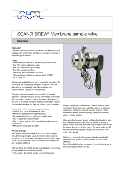
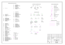
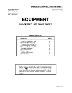
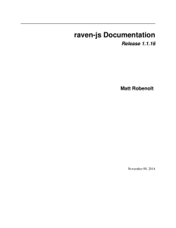
Installation, Operation and Maintenance Manual SAMPLE SENTRY® II Sample Conditioning Modules SPD 1.1.16 Rev. 7 SENTRY EQUIPMENT CORP PO Box 127 Oconomowoc, WI 53066 USA Phone: 262.567.7256 Fax: 262.567.4523 Email: [email protected] www.sentry-equip.com Sample Sentry® II SPD 1.1.16 Rev 7 Certification The Sample Sentry®II has been tested and is certified to the following standards: Product Safety: Machinery Directive 98/37/EC Required Standards include: EN ISO 12100-1:2003 Safety of machinery – Basic concepts, general principles for design. Basic terminology, methodology EN ISO 12100-2:2003 Safety of machinery – Basic concepts, general principles for design. Technical principles SENTRY EQUIPMENT CORP • 262.567.7256 • Fax: 262.567.4523 • [email protected] • www.sentry-equip. com i Sample Sentry® II SPD 1.1.16 Rev 7 TABLE OF CONTENTS SPECIFICATIONS........................................................................................................................ 1 SAFETY PRECAUTIONS............................................................................................................. 2 Use of Hazard Information ................................................................................................ 2 Definitions ......................................................................................................................... 2 GENERAL DESCRIPTION........................................................................................................... 4 OPERATION ................................................................................................................................ 9 Description of Controls...................................................................................................... 9 Screen Descriptions........................................................................................................ 11 Operation Screen ................................................................................................ 12 Alarm Screen....................................................................................................... 13 Main Menu........................................................................................................... 13 Display Intensity .................................................................................................. 14 Analog Inputs ...................................................................................................... 14 Scale ................................................................................................................... 14 Setup ................................................................................................................... 15 Flow Rates .......................................................................................................... 15 Blowdown Time ................................................................................................... 16 Continued Setup ................................................................................................. 16 Pressures ............................................................................................................ 17 PRV Type ............................................................................................................ 17 Clean ................................................................................................................... 18 Continued Setup (Screen 2)................................................................................ 18 Alarm Setup......................................................................................................... 18 Units .................................................................................................................... 19 Options ................................................................................................................ 19 MODBUS® ........................................................................................................... 20 PID ...................................................................................................................... 20 Home................................................................................................................... 20 Resetting Alarms ................................................................................................. 21 Motor Alarm......................................................................................................... 21 INSTALLATION ......................................................................................................................... 21 Unpacking ....................................................................................................................... 22 Mounting ......................................................................................................................... 22 Connections .................................................................................................................... 22 Electrical Connections .................................................................................................... 24 Power Connection........................................................................................................... 24 Startup ............................................................................................................................ 25 MAINTENANCE ......................................................................................................................... 26 Sample Cooler ................................................................................................................ 26 Disassembly & Reassembly................................................................................ 26 SENTRY EQUIPMENT CORP • 262.567.7256 • Fax: 262.567.4523 • [email protected] • www.sentry-equip. com ii Sample Sentry® II SPD 1.1.16 Rev 7 VREL®/Needle Valve....................................................................................................... 26 Inlet Isolation Valve......................................................................................................... 27 Backpressure Regulating/Relief Valve............................................................................ 27 Controller ........................................................................................................................ 28 Fuses .................................................................................................................. 28 Analog Input Calibration ...................................................................................... 30 Calibration....................................................................................................................... 30 Factory Settings – ............................................................................................... 32 TROUBLESHOOTING GUIDE ................................................................................................... 33 FACTORY ASSISTANCE .......................................................................................................... 34 SPARE PARTS LIST.................................................................................................................. 35 WARRANTY ............................................................................................................................... 37 APPENDIX A - MODBUS® ........................................................................................................ 39 List of Tables Table 1 – Control Descriptions .................................................................................................................. 9 Table 2 – Power Cord Requirements ...................................................................................................... 24 Table 3 – Channel Calbration Reference ................................................................................................ 31 Table 4 – Factory Settings....................................................................................................................... 32 Table 5 – Troubleshooting Guide ............................................................................................................ 33 Table 6 – MODBUS® Registers .............................................................................................................. 40 SENTRY EQUIPMENT CORP • 262.567.7256 • Fax: 262.567.4523 • [email protected] • www.sentry-equip. com iii Sample Sentry® II SPD 1.1.16 Rev 7 List of Figures Figure 1 – System P&ID ............................................................................................................................ 5 Figure 2 – System P&ID With Secondary Cooling..................................................................................... 6 Figure 3 – Controller Front Panel ............................................................................................................ 10 Figure 4 – Screen Navigation .................................................................................................................. 11 Figure 5 – Operation Screen ................................................................................................................... 12 Figure 6 – Alarm Screen.......................................................................................................................... 13 Figure 7 – Main Menu.............................................................................................................................. 13 Figure 8 – Display Intensity ..................................................................................................................... 14 Figure 9 – Analog Input Menu ................................................................................................................. 14 Figure 10 – Scale Selection Screen ........................................................................................................ 14 Figure 11 – Change Scale ....................................................................................................................... 15 Figure 12 – Setup Screen........................................................................................................................ 15 Figure 13 – Flow Rates............................................................................................................................ 15 Figure 14 – Blowdown Time .................................................................................................................... 16 Figure 15 – Continued Setup................................................................................................................... 16 Figure 16 – Startup Pressure................................................................................................................... 17 Figure 17 – PRV Type ............................................................................................................................. 17 Figure 18 – VREL® Cleaning Frequency ................................................................................................. 18 Figure 19 – Continued Setup (Screen 2) ................................................................................................. 18 Figure 20 – Alarm Setup.......................................................................................................................... 18 Figure 21 – Units ..................................................................................................................................... 19 Figure 22 – Measurement Options .......................................................................................................... 19 Figure 23 – MODBUS® Setup................................................................................................................. 20 Figure 24 – PID Setup ............................................................................................................................. 20 Figure 25 – Manual Home ....................................................................................................................... 20 Figure 26 – General Arrangement (High Pressure Model) ...................................................................... 23 Figure 27 – Channel Configuration on SSII CPU Board .......................................................................... 30 Figure 28 – MODBUS® Setup................................................................................................................. 39 SENTRY EQUIPMENT CORP • 262.567.7256 • Fax: 262.567.4523 • [email protected] • www.sentry-equip. com iv Sample Sentry® II SPD 1.1.16 Rev 7 WARNING notices as used in this manual apply to hazards or unsafe practices, which could result in personal injury or death. CAUTION notices apply to hazards or unsafe practices which could result in minor personal injury or property damage. NOTES highlight procedures and contain information which assists the operator in understanding the information contained in this manual. WARNING Do not install, maintain, or operate this equipment without reading, understanding and following the proper Sentry Equipment Corp. instructions. Otherwise, injury or damage or both may result. NOTICE The information contained in this document is subject to change without notice. Sentry Equipment Corp, its employees, agents, and the authors of and contributors to this document specifically disclaim all liabilities and warranties, express and implied (including warranties of merchantability and fitness for a particular purpose), for the accuracy, currency, completeness, and/or reliability of the information contained herein and/or for the fitness for any particular use and/or for the performance of any material and/or equipment selected in whole or part with the user of/or in reliance upon information contained herein. Selection of materials and/or equipment is at the sole risk of the user of this publication. This document contains proprietary information. No part of this document may be photocopied or reproduced without the prior written consent of Sentry Equipment Corp. Sentry Equipment Corp 966 Blue Ribbon Circle North PO Box 127 Oconomowoc, WI 53066 Phone: Fax: 262.567.7256 262.567.4523 Normal business hours: 7:00 a.m. to 4:30 p.m. CST (U.S. Central Time), Monday through Friday SENTRY EQUIPMENT CORP • 262.567.7256 • Fax: 262.567.4523 • [email protected] • www.sentry-equip. com v Sample Sentry® II SPD 1.1.16 Rev 7 SPECIFICATIONS Specifications are subject to change without notice. Applications: Sample Sentry® II is designed to meet requirements for representative sampling by maintaining a constant flow rate with varying inlet conditions. Models: Low Pressure Models (LP) 0 – 500 PSI (0 – 35 bar) @ 450 F (232 C) High Pressure Models (HP)* 500 – 3030 PSI (35 – 209 bar) @1000 F (540 C) Flow Control: Range ................ 0 – 3400 cc/min Accuracy ............. ± 50 cc/min Measurements: Final Sample Temperature Cooling Water Outlet Temperature Inlet Sample Temperature Inlet Sample Pressure Analyzer Sample Pressure Sample Flow Rate Power: Input Voltage: 100 - 240 VAC Frequency Range: 50/60 Hz Input Current: 1.5 A / 115 V 0.9 A / 230 V Compressed Air: Consumption : < 0.2 scfm Pressure : 80 PSI minimum Dimensions: with sink 14 in. x 43 in. (356 mm x 1092 mm) without sink 14 in. x 36 in. (356 mm x 914 mm) Mounting: Wall mount using four 3/8” bolts Ambient Temperature: 0-50 C (32-122 F) RH 95% max. non-condensing at 40 C (104 F) max. Approximate Shipping Weight: 65 lbs max (29 kg) Pressure Measurements: Range ................ 0 – 3000 PSI (0 – 207 bar) Accuracy ............. ± 0.5% Temperature Measurements: Range ................ 32 – 250 F (0 – 121 C) Accuracy ............. ± 1 F Alarm Relay Contact Rating: Max. operating voltage ........... 250 VAC 220 VDC Max. switching capacity ......... 30 W, 62.5 VA inductive 60 W, 125 VA resistive Communications: Protocol................................... MODBUS® Network................................... RS-485 * Higher pressure model available. Display: Graphical Vacuum Fluorescent Display SENTRY EQUIPMENT CORP • 262.567.7256 • Fax: 262.567.4523 • [email protected] • www.sentry-equip. com 1 Sample Sentry® II SPD 1.1.16 Rev 7 SAFETY PRECAUTIONS Please read the entire manual before attempting to unpack, set up or operate this product. Pay careful attention to all warnings, cautions and notes. Failure to do so could result in serious personal injury or equipment damage. Use of Hazard Information If multiple hazards exist, the signal word corresponding to the greatest hazard shall be used. Definitions Indicates an imminently hazardous situation that, if not avoided, will result in death or serious injury. Indicates a potentially hazardous situation that, if not avoided, could result in death or serious injury. Indicates a potentially hazardous situation that, if not avoided, may result in minor or moderate injury. CAUTION used without the safety alert symbol indicates a potentially hazardous situation that, if not avoided, may result in property damage. NOTE Information that requires special emphasis SHALL This word understood to be mandatory SHOULD This word understood to be advisory SENTRY EQUIPMENT CORP • 262.567.7256 • Fax: 262.567.4523 • [email protected] • www.sentry-equip. com 2 Sample Sentry® II SPD 1.1.16 Rev 7 Indique une situation imminente et dangeureuse qui doit être évité immédiatement afin d’éviter tout risque de blessures sérieuses et qui pourrait même entraîner la mort. AVERTISSEMENT Indique une situation potentiellement dangeureuse et qui doit être évité immédiatement afin d’éviter tout risque de blessures sérieuses et qui pourrait même entraîner la mort. PRÉCAUTION Indique une situation potentiellement dangeureuse et qui doit être évité immédiatement afin d’éviter tout risque de blessures mineures. PRÉCAUTION ATTENTION une utilisation sans le symbole de sécurité indique une situation potentiellement dangeureuse et que si elle n’est pas évité, pourrait entrainer des dommages à la propriété. NOTE Informations requérant une attention spéciale DOIT Ce mot indique une obligation POURRAIT Ce mot indique un avertissement SENTRY EQUIPMENT CORP • 262.567.7256 • Fax: 262.567.4523 • [email protected] • www.sentry-equip. com 3 Sample Sentry® II SPD 1.1.16 Rev 7 GENERAL DESCRIPTION Flow control of liquid sample is important to help assure the quality of the samples and repeatability of the analytical results. Constant flow in the sample line minimizes the chance of modifying the chemistry of the samples of high purity water through entrapment and/or release of soluble species from deposits in the system. Sample inlet temperature and flow are easily controlled under constant conditions. However, since sample pressures typically fluctuate, maintaining a representative sample can be difficult and labor intensive. The traditional manual sample conditioning system can require constant adjustment during startup or as plant conditions change. Sample Sentry® II is designed to meet requirements for representative sampling by maintaining a constant flow rate with varying inlet conditions. Automated flow control is achieved by continuously monitoring the sample flow rate and controlling a motorized pressure reduction valve (PRV). An acutuated ball valve and solenoid valve controls the flow path, allowing for automatic startup and shutdown of the system. Flow control is also available in a manual mode, allowing the operator to control the system with a keypad on the controller. Sensors allow the controller to monitor temperature, pressure, and flow and shutdown the system when an alarm occurs. Programmable options in the controller allow Sample Sentry®II to conform to a variety of sampling applications. SENTRY EQUIPMENT CORP • 262.567.7256 • Fax: 262.567.4523 • [email protected] • www.sentry-equip. com 4 Sample Sentry® II SPD 1.1.16 Rev 7 Figure 1 is a typical P&ID of a Sample Sentry® II system. CUSTOMER CONNECTIONS 1) SAMPLE INLET 2) SAMPLE OUTLET 3) PRIMARY COOLING WATER INLET 4) PRIMARY COOLING WATER OUTLET 5) SECONDARY COOLING WATER INLET* 6) SECONDARY COOLING WATER OUTLET* 7) SINK DRAIN 8) AIR INLET 1 3 V-2 V-5 TE 3 COOLER DRAIN SC-1 V-4 4 PT 1 V-1 SV-1 A 8 S M PRV (VREL / NEEDLE VALVE) CONTROLLER TE 1 FT 1 FE 1 S 2 SV-2 BPR/RV GRAB SAMPLE SINK* * = OPTIONAL ITEMS 7 Figure 1 – System P&ID SENTRY EQUIPMENT CORP • 262.567.7256 • Fax: 262.567.4523 • [email protected] • www.sentry-equip. com 5 Sample Sentry® II SPD 1.1.16 Rev 7 Figure 2 is a P&ID of a Sample Sentry® II system with secondary cooling. CUSTOMER CONNECTIONS 1) SAMPLE INLET 2) SAMPLE OUTLET 3) PRIMARY COOLING WATER INLET 4) PRIMARY COOLING WATER OUTLET 5) SECONDARY COOLING WATER INLET* 6) SECONDARY COOLING WATER OUTLET* 7) SINK DRAIN 8) AIR INLET 1 V-2 4 V-5 TE 3 COOLER DRAIN SC-1 V-4 3 PT 1 V-1 SV-1 A 8 S M PRV (VREL / NEEDLE VALVE) TE 2 * 6 SC-2 * 5 CONTROLLER TE 1 FT 1 FE 1 S 2 SV-2 BPR/RV GRAB SAMPLE SINK* * = OPTIONAL ITEMS 7 Figure 2 – System P&ID With Secondary Cooling SENTRY EQUIPMENT CORP • 262.567.7256 • Fax: 262.567.4523 • [email protected] • www.sentry-equip. com 6 Sample Sentry® II SPD 1.1.16 Rev 7 Upon power being supplied to the Sample Sentry® II, the unit enters its startup routine. During Startup, always ensure that unit’s sample isolation valve is closed (Located next to customer connection 1 in Figure1 and Figure 2). During this startup routine, the unit’s revision date and a Sentry logo are displayed. See Figure 3. During the unit’s startup routine, the fully closed position of the PRV is being located. Once located, the unit verifies the fully closed position is correct by cycling through the full range of the PRV. The Unit then adjusts to the PRV home set point. Any time that the Sample Sentry® II power is reset, the unit will enter its startup routine and locate the PRV’s fully closed position, followed by the units PRV home position. Once startup has been completed successfully, the Operation screen will be displayed. Refer to Figure 5. Sample Sentry® II has two modes of operation, Manual and Automatic. Automatic mode is comprised of the following states: Start, Blowdown, Sample, and Stop. Start is the first state in Automatic mode. While in the Start state the valves V-1 and SV-2 are closed. The PRV should be in its home set point position. For older models, this home set point is not customer adjustable and is set to zero. On new models, the PRV home set point position can be customer adjustable between 0 and 52 (0 being fully closed and 52 being fully open) If an adjustable set point is desired, please contact Sentry Equipment Corp. for instructions on how to adjust this PRV home setpoint. The system continually monitors the inlet pressure at PT1 and compares it to a programmed Startup Pressure set point in the controller. When the inlet pressure is greater than the Startup Pressure set point, the system will advance to the Blowdown state. When enabled, the Blowdown state initiates a controlled blowdown sequence by opening V-1 and closing SV-2. Blowdown is designed to flush the sample line while preventing flow to analyzers. The controller continually adjusts the PRV, maintaining a flow rate at the programmed blowdown flow rate set point. By closing SV-2, sample flow to analyzers is stopped and the entire sample flows to the grab sample. Sample Sentry®II remains in the Blowdown state until the blowdown timer expires. The blowdown timer is a programmable set point in the controller. NOTE Ensure sufficient blowdown time and flowrate are obtained to remove debris from the sample stream prior to sending sample to the analyzers. After blowdown, Sample Sentry®II advances to the Sample state. In the Sample state, SV-2 opens allowing flow to analyzers. The controller continually adjusts the PRV, maintaining a flow rate at the programmed sample flow rate. The system remains in the Sample state until one of the following conditions are met: 1. Low Flow a. The PRV is full open. b. The total flow rate falls below the shutdown flow rate set point. 2. Low Pressure a. The pressure falls below the shutdown pressure set point. SENTRY EQUIPMENT CORP • 262.567.7256 • Fax: 262.567.4523 • [email protected] • www.sentry-equip. com 7 Sample Sentry® II SPD 1.1.16 Rev 7 When one of the above conditions is met, the system advances to the Stop state. In the Stop state, the controller closes SV2, adjusts the PRV to its home set point, and then closes V-1. After all three valves are in their respective positions; the system will advance to the Start state if automatic startup is enabled or Manual mode if disabled. The position of the pressure reduction valve and state of the valves are graphically displayed on the user interface. Temperature, pressure, and flow are also displayed. The MODBUS® feature provides added advantages including remote monitoring and control of the system. The capabilities of MODBUS® are further addressed in Appendix A. SENTRY EQUIPMENT CORP • 262.567.7256 • Fax: 262.567.4523 • [email protected] • www.sentry-equip. com 8 Sample Sentry® II SPD 1.1.16 Rev 7 OPERATION To ensure the protection provided by this equipment is not impaired, this equipment must not be installed or used in any manner other than that which is specified in this manual. AVERTISSEMENT Afin de s’assurer que la protection prévue par cette pièce d’équipement n’est pas défaillante, cet équipement ne doit pas être installé ou utilisé de manière autre que spécifié dans le manuel. Description of Controls Table 1 and Figure 3 describe controls on the Sample Sentry® II controller. DESCRIPTION MENU key ENTER key ESC key Arrow keys ▲ ▼ Cursor FUNCTION From the operation screen in when the unit is in Manual mode, pressing the MENU key will display the password screen for the main menu. In order to enter the menu screen you must enter the password 101 followed by the ENTER key. If a correct password is entered, the main menu screen will appear. From an alarm screen, pressing the MENU key will clear the alarm. From the operation screen, pressing the ENTER key will toggle the controller between the Automatic and Manual modes. While navigating through the menu screens, pressing the ENTER key will select the option indicated by the cursor (►). From the operation screen, pressing the ESC key will toggle the states between Blowdown and Sample. While in the menu screens, pressing the ESC key will exit the current screen. Any changes are automatically saved. While in Manual mode, pressing the arrow keys will open and close the PRV. While navigating through the menu screens, use the arrow keys to move the cursor to the option you want to choose. While editing fields and timers, use the arrow keys to change the value in the current field. Indicates the cursor position on the menu screens. ► Table 1 – Control Descriptions SENTRY EQUIPMENT CORP • 262.567.7256 • Fax: 262.567.4523 • [email protected] • www.sentry-equip. com 9 Sample Sentry® II SPD 1.1.16 Rev 7 Figure 3 – Controller Front Panel SENTRY EQUIPMENT CORP • 262.567.7256 • Fax: 262.567.4523 • [email protected] • www.sentry-equip. com 10 Sample Sentry® II SPD 1.1.16 Rev 7 Screen Descriptions Figure 4 shows the screen structure in the Sample Sentry® II controller. Operation Screen Main Menu Setup Analog Inputs Auto Cal Flow Rates Scale Manual Cal Blowdown Time Startup Pressure Alarms Display Units PRV Type Options More Clean MODBUS More PID Home Figure 4 – Screen Navigation SENTRY EQUIPMENT CORP • 262.567.7256 • Fax: 262.567.4523 • [email protected] • www.sentry-equip. com 11 Sample Sentry® II SPD 1.1.16 Rev 7 Operation Screen The operation screen is the main screen on the Sample Sentry®II. This screen contains information indicating the status of the system. While in Manual mode, the system is controlled from the operation screen. I n l e t 1 B l o w d o w 0 : 2 7 : 3 V 1 S V 5 0 0 n 1 7 2 P S I 4 0 7 c c m i n P R V Figure 5 – Operation Screen Figure 5 shows a typical operation screen for the Sample Sentry®II. The top line displays temperature and pressure data. The screen periodically refreshes to show a different measurement. Only measurements that are enabled are displayed. Line 4 displays the state of the three valves. Figure 5 currently shows valve V1 open, SV2 closed, and the PRV partially open. Line 2 displays the state of the system, including the total flow rate. The 7 possible states are Manual, Start, Blowdown, Sample, Stop, Remote and Clean. Manual: While in manual mode, the system can be controlled with the keypad on the front of the controller. Pressing the MENU key will display the Main Menu password screen. To place the system in Automatic mode, press the ENTER key. Pressing the ESC key will toggle valves V1 and SV2 between open and closed. Holding the ▲ key will open the PRV, while holding the ▼ key will close the PRV. Start: The controller waits in the Start state until the inlet pressure is greater than the programmed startup pressure. The only key that is functional while in the Start state is the ENTER key. Pressing the ENTER key will return the system to Manual mode. Blowdown: Flow to analyzers is stopped by closing SV2, forcing the entire sample to flow to the grab sample. When the system is in Blowdown, the time remaining in Blowdown is displayed on line 3. Pressing the ENTER key will return the system to Manual mode. Pressing the ESC key will advance the system to Sample. Sample: The controller opens SV2, allowing flow to analyzers. Pressing the ENTER key will return the system to Manual mode. Pressing the ESC key will return the system to Blowdown. Stop: The Stop state occurs when the total flow falls below a shutdown set point and the PRV is full open or if the pressure is lower than the shutdown pressure set point. During the Stop state V1 is closed, the PRV is adjusted to it set point, and SV2 is closed. After these valves are adjusted, the controller will advance to Start if automatic startup is enabled or Manual if disabled. SENTRY EQUIPMENT CORP • 262.567.7256 • Fax: 262.567.4523 • [email protected] • www.sentry-equip. com 12 Sample Sentry® II SPD 1.1.16 Rev 7 Remote: Remote indicates the system is being controlled remotely with the MODBUS® communications port. While in the Remote mode, the controller enters the Blowdown and Sample states as determined from remote commands. Pressing the ENTER key will return the system to Manual mode. Clean: When the self-clean feature is enabled, the controller periodically actuates the VREL® in an attempt to free potential blockages. The cleaning cycles opens the VREL® for 5 seconds, waits for 3 seconds, closes the VREL® for 5 seconds, waits for 3 seconds. This process is repeated 5 times. After the cleaning cycle is complete, the controller returns to the previous state. Alarm Screen A l a r m H i g h T e m p e r a t u r e T o u t = 1 2 5 F Figure 6 – Alarm Screen Figure 6 shows a typical alarm screen. Anytime an alarm condition occurs, the alarm screen takes priority over the existing screen. The alarm screen will flash twice per second, alerting the operator of the problem. After the alarm condition has cleared, pressing the MENU button will reset the alarm. Main Menu M a i n M e n u ►S e t u p A n a l o g I n p u t s D i s p l a y Figure 7 – Main Menu Figure 7 shows the main menu screen. The main menu is reached by pressing the MENU key from the operation screen with the system in Manual. The cursor indicates the option you wish to choose. Move the cursor by using the ▲ and ▼ keys. Select the option by using the ENTER key. To exit this screen and return to the operation screen, press the ESC key. The Main Menu password is 101. SENTRY EQUIPMENT CORP • 262.567.7256 • Fax: 262.567.4523 • [email protected] • www.sentry-equip. com 13 Sample Sentry® II SPD 1.1.16 Rev 7 Display Intensity D i s p l a y I n t e n s i L e v e l 1 - 8 6 t y Figure 8 – Display Intensity Figure 8 shows the Display Intensity screen. This screen allows the intensity of the graphical display to be adjusted. To increase the intensity, use the ▲ key. To decrease the intensity, use the ▼ key. The display setting is represented by a number between 1 and 8, with 8 representing the brightest setting. Press the ESC key to save changes and return to the main menu. Analog Inputs A n ►A S M a u c a l t a n o g I n p u t S e t u p o C a l i b r a t i o n l e u a l C a l i b r a t i o n Figure 9 – Analog Input Menu Figure 9 shows the analog input menu screen. This screen can be accessed by enter 202 for the Analog Input Setup Password. The cursor indicates the option you wish to choose. Move the cursor using the ▲ and ▼ keys. Select the option using the ENTER key. To exit this screen and return to the main menu, press the ESC key. For information on calibrating the analog inputs, please refer to the Maintenance section of this manual. Scale S c a l e C h a n n e l 1 Figure 10 – Scale Selection Screen Figure 10 shows the scale channel selection screen. To change the selected channel to scale, use the ▲ and ▼ keys. To select the channel, press the ENTER key. To return to the analog input setup screen, press the ESC key. SENTRY EQUIPMENT CORP • 262.567.7256 • Fax: 262.567.4523 • [email protected] • www.sentry-equip. com 14 Sample Sentry® II SPD 1.1.16 Rev 7 S c a l e C h a n n e l 3 M i n 0 P S I Figure 11 – Change Scale Figure 11 shows the change scale screen. This screen is displayed after selecting the channel in the scale selection screen. To change the Min value, use the ▲ and ▼ keys. When finished changing the Min value, press the ENTER key to display and alter the Max value. Change the Max value using the ▲ and ▼ keys. When finished changing the Max value, press the ENTER key to return to the scale selection screen. Setup S e t u p R a t e s B l o w d o w n T i m e Mo r e ►F l o w Figure 12 – Setup Screen Figure 12 shows the setup screen. The cursor indicates the option you wish to choose. Move the cursor using the ▲ and ▼ keys. Select the option using the ENTER key. To exit this screen and return to the main menu, press the ESC key. Flow Rates F l o w R a t e s B l o w d o w n 1 5 0 0 c c / m i n Figure 13 – Flow Rates Figure 13 shows the flow rates setup screen. The first set point displayed is the blowdown flow rate. To adjust the set point, use the ▲ and ▼ keys. To change the set point in counts of 100, hold the MENU key while using the ▲ and ▼ keys. When finished changing the displayed set point, press the ENTER key to display the next set point. After setting the last flow rate, pressing ENTER will return to the setup screen. The following flow rates can be programmed: Blowdown: This flow rate is used during the Blowdown state. During this time, the entire sample flows to the grab sample, preventing flow to analyzers. This mode is designed to flush the sample at a slightly higher flow rate than the sample state. NOTE EPRI recommends a blowdown velocity no greater than 125% the normal sampling velocity. SENTRY EQUIPMENT CORP • 262.567.7256 • Fax: 262.567.4523 • [email protected] • www.sentry-equip. com 15 Sample Sentry® II SPD 1.1.16 Rev 7 Sample: This flow rate is used during the Sample state. During this time, sample is allowed to flow to analyzers. Shutdown: This flow rate setting is used to determine when the system should shut down. When the total flow is less than this set point and the PRV is full open, the system will shut down. NOTE If the desire is for the system to never shut down, set the Shutdown flow rate to 0 cc/min, and disable the Shutdown pressure setpoint. Blowdown Time B l o w d o w n T i m e h h : m m : s s 0 : 4 5 : 0 0 Figure 14 – Blowdown Time Figure 14 shows the blowdown time setup screen. This setting controls the duration the system stays in blowdown after startup. To change the second’s field, use the ▲ and ▼ keys. To change the minutes field, hold the ENTER key while using the ▲ and ▼ keys. To change the hour’s field, hold the MENU key while using the ▲ and ▼ keys. To return to the setup screen, press the ESC key. NOTE To disable blowdown, set the blowdown time to 0:00:00. Continued Setup S e t u p C o n t i n u e d P r e s s u r e P R V T y p e C l e a n M o r e ►S t a r t u p Figure 15 – Continued Setup Figure 15 shows the continued setup screen. The cursor indicates the option you wish to choose. Move the cursor using the ▲ and ▼ keys. Select the option using the ENTER key. To exit this screen and return to the setup screen, press the ESC key. SENTRY EQUIPMENT CORP • 262.567.7256 • Fax: 262.567.4523 • [email protected] • www.sentry-equip. com 16 Sample Sentry® II SPD 1.1.16 Rev 7 Pressures S t a r t u p P r e s s u r e 9 0 0 P S I Figure 16 – Startup Pressure Figure 16 shows the pressures screen. To adjust the set-point, use the ▲ and ▼ keys. Holding the MENU key while using the ▲ and ▼ keys changes the set-point in increments of 100. When finished changing the displayed set point, press the ENTER key to display the next set point. After setting the last pressure, pressing ENTER will return to the setup screen. The following pressures can be programmed: Startup: The first set point displayed is the startup pressure. This inlet pressure set point is used to determine when Sample Sentry®II should startup. Shutdown: This pressure setting is used to determine when the system should shut down. When the pressure is less than this set point, the system will shut down. To disable automatic shutdown on low pressure, reduce the shutdown pressure until it reads “Disabled.” NOTE Ensure that there is sufficient pressure differential between the startup pressure set point and shutdown pressure setpoint so that the Sample Sentry®II does not enter a continuous loop senario. (ie. Startup pressure must always be suffieciently higher than Shutdown pressure to account for pressure drops during startups. PRV Type P R V T y p e V R E L Figure 17 – PRV Type Figure 17 shows the PRV selection screen. To toggle the PRV selection between the VREL® and Needle valve, use the ▲ or ▼ key. To return to the continued setup screen, use the ESC key. SENTRY EQUIPMENT CORP • 262.567.7256 • Fax: 262.567.4523 • [email protected] • www.sentry-equip. com 17 Sample Sentry® II SPD 1.1.16 Rev 7 Clean A u t o C l e a n F r e q u e n c y d d : h h : m m 0 : 0 0 : 0 0 Figure 18 – VREL® Cleaning Frequency Figure 18 shows the Auto Cleaning Frequency screen. This screen sets the frequency between auto cleaning cycles for the VREL®. When auto clean is enabled the controller periodically actuates the VREL® to prevent plugging. To change the minutes field, use the ▲ and ▼ keys. To change the hours field, hold the ENTER key while using the ▲ and ▼ keys. To change the day’s field, hold the MENU key while using the ▲ and ▼ keys. To return to the continued setup screen, use the ESC key. NOTE To disable auto cleaning, set the frequency to 0:00:00. Continued Setup (Screen 2) S ►A l U n O p e a i t t r t i u p C o n t i n u e d m s M O D B U S s P I D o n s H o m e Figure 19 – Continued Setup (Screen 2) Figure 19 shows the second continued setup screen. The cursor indicates the option you wish to choose. Move the cursor using the ▲ and ▼ keys. Select the option using the ENTER key. To exit this screen and return to the previous screen, press the ESC key. Alarm Setup O u t A l a r m S e t u p l e t T e m p e r a t u r e 1 2 0 F Figure 20 – Alarm Setup Figure 20 shows the alarm setup screen. Use the ▲ and ▼ keys to change the alarm threshold. Use the ENTER key to advance to the next alarm point. After all alarm levels are set, the screen automatically returns to the continued setup screen (screen 2). The following alarm conditions can be set: SENTRY EQUIPMENT CORP • 262.567.7256 • Fax: 262.567.4523 • [email protected] • www.sentry-equip. com 18 Sample Sentry® II SPD 1.1.16 Rev 7 Outlet Temperature: High temperature alarm for the sample temperature to analyzers. A high outlet temperature will trigger a shutdown and set the common alarm relay. Low Flow: Alerts operators the total flow is below the alarm threshold. The common alarm relay is set. Low Flow Hysteresis: This set point determines when the low flow alarm clears. The system will remain in low flow alarm until the total flow rises above the low alarm level plus the alarm hysteresis. Low Pressure: Alerts operators the pressure is below the alarm threshold. The common alarm relay is set. Low Pressure Hysteresis: This set point determines when the Pressure alarm clears. The system will remain in low-pressure alarm until the pressure rises above the low alarm level plus the alarm hysteresis. Units U n i t s S e t u p E n g l i s h Figure 21 – Units Figure 21 shows the unit selection screen. To toggle the displayed units between English and SI, use the ▲ and ▼ keys. To return to the previous screen, use the ENTER key. Options M e a s u r e m e n t O p t i o n s I n l e t P r e s s u r e E n a b l e d Figure 22 – Measurement Options Figure 22 shows the measurement options screen. This screen is used to enable or disable optional measurement options. To enable or disable the displayed option, use the ▲ or ▼ key. To advance to the next measurement option, use the ENTER key. After all options have been set, the screen will return to the continued setup screen (screen 2). Available options are: Inlet Pressure and Temperature, Outlet Pressure and Temperature, and Cooling Water Temperature. SENTRY EQUIPMENT CORP • 262.567.7256 • Fax: 262.567.4523 • [email protected] • www.sentry-equip. com 19 Sample Sentry® II SPD 1.1.16 Rev 7 MODBUS® M O D B U S ►A d d r e s s B A U D S e t u p 1 9 6 0 0 b p s Figure 23 – MODBUS® Setup Figure 23 shows the MODBUS® setup screen. This screen allows the MODBUS® address and BAUD rate to be changed. For further information on using the MODBUS® feature, please refer to Appendix A. PID P I D S e t u p P a s s w o r d 0 0 0 0 Figure 24 – PID Setup Figure 24 shows the PID setup screen. The PID parameters should only be changed with the assistance of Sentry Equipment Corp. For this reason, PID parameters are password protected. If the system needs tuning, please contact Sentry Equipment Corp. for assistance. Home M a n u a l H o m e E n c o d e r Z = 0 E n t e r t o s e t H o m e Figure 25 – Manual Home Figure 25 shows the set home screen. . The Manual Home feature should only be changed with the assistance of Sentry Equipment Corp. For this reason, the Manual Home feature is password protected. If the system needs tuning, please contact Sentry Equipment Corp. for assistance. This screen is used to manually tune the PRV and motor. To move the PRV, use the ▲ and ▼ keys. After the PRV is in the home position, press the ENTER key to reset the encoder count. To return to the previous screen, press the ESC button. NOTE: Improper use of the Manual Home feature will damage the unit, call Sentry Equipment Corp to receive instructions on how use this feature. Manual homing of the PRV by the customer is rarely needed. The Sample Sentry®II is designed to auto-home upon a restart of the system. Typically, cycling power will properly correct any PRV’s that have their home location set incorrectly. SENTRY EQUIPMENT CORP • 262.567.7256 • Fax: 262.567.4523 • [email protected] • www.sentry-equip. com 20 Sample Sentry® II SPD 1.1.16 Rev 7 Resetting Alarms Motor Alarm A Motor alarm will occur when the torque required to move the PRV is greater than the maximum torque the motor is capable of supplying. Typically, a motor alarms occurs because debris becomes lodged in the PRV, or the PRV’s home position was set incorrectly. Follow the below procedure to dislodge or clean any debris from the VREL. Applying excessive torque on the PRV Shaft or PRV coupling will result in damage to the unit. Follow the appropriate procedure when dislodging PRV. 1) Close the sample inlet isolation valve on the SSII 2) Remove power from the SSII. 3) Remove VREL and clean debris from VREL 4) Verify VREL shaft opens and closes freely with little resistance 5) Replace VREL (replacing VREL near the fully closed position will reduce startup time) 6) Apply power to the SSII Wait for SSII unit to finish it’s startup routine (date screen will no longer be shown) INSTALLATION SENTRY EQUIPMENT CORP • 262.567.7256 • Fax: 262.567.4523 • [email protected] • www.sentry-equip. com 21 Sample Sentry® II SPD 1.1.16 Rev 7 This instrument should be installed by qualified technical personnel to ensure adherence to all applicable electrical codes. AVERTISSEMENT Cet instrument doit être installé par un technicien certifié afin d’assurer que toutes les normes au code électrique sont respectées. To ensure the protection provided by this equipment is not impaired, this equipment must not be installed or used in any manner other than that which is specified in this manual. AVERTISSEMENT Afin de s’assurer que la protection prévue par cette pièce d’équipement n’est pas défaillante, cet équipement ne doit pas être installé ou utilisé de manière autre que spécifié dans le manuel. Unpacking ® After carefully removing the Sample Sentry II from its shipping carton, inspect it for any damage. Report damages to the shipper immediately. Mounting Bolt the units to the wall using four 3/8" bolts. To simplify installation, first mount the unistrut to the wall and then mount the single line to the unistrut. Connections Refer to Figure 26 for connection locations. 1. Connect cooling water inlet 3 and outlet 4 connections on primary cooler. (Secondary cooler optional – Inlet 5 , Outlet 6 ) 2. Connect the inlet sample line 1 and outlet sample line 2 . 3. Connect optional sink drain 7 . 4. Connect air inlet 8 . SENTRY EQUIPMENT CORP • 262.567.7256 • Fax: 262.567.4523 • [email protected] • www.sentry-equip. com 22 Sample Sentry® II SPD 1.1.16 Rev 7 Figure 26 – General Arrangement (High Pressure Model) SENTRY EQUIPMENT CORP • 262.567.7256 • Fax: 262.567.4523 • [email protected] • www.sentry-equip. com 23 Sample Sentry® II SPD 1.1.16 Rev 7 Electrical Connections Electrical Shock Hazard – All input and output wiring should be installed in such a manner that access to bare copper is prohibited during normal operation. AVERTISSEMENT Avertissement de choc électrique- Tout le filage devra être installé de manière à éviter que toute partie de fil soit dénudé (sur le cuivre) durant l’utilisation normale An access hole sized for ½” NPT (15 mm) electrical conduit fitting is provided on the bottom of the enclosure. A sealing type conduit fitting is required to maintain the enclosure’s rating. Power Connection The Sample Sentry®II contains two circuit boards stacked in the enclosure. The power connection is located on the output board, the bottom board in the circuit board stack. The Sample Sentry®II contains a universal power supply. The power supply is capable of accepting an input voltage range of 100-240 VAC and frequency of 50 or 60 Hz. The Sample Sentry®II will automatically operate with power supplied in this range. A power supply lead of 16 AWG (1.3 mm2) copper wire is recommended. It is recommended the Sample Sentry®II be connected to an electrical outlet or outlet strip with surge suppression and filtering. A suitable external over-current protection device such as a fuse or circuit breaker (15 A) is recommended for both the hot (L) and neutral (N) leads. Using this method, the plug will serve as the disconnect device. The cord and plug shall comply with the following standards: Location Cord Plug United States ANSI/UL 817 ANSI/UL 498 Canada CSA C22.2 No. 21 or C22.2 No. 49 CSA C22.2 No. 21 and C22.2 No. 42 European Community IEC 60227 or 60245 Appropriate IEC standard Table 2 – Power Cord Requirements If desired, the Sample Sentry®II may also be hard wired to instrument-quality power using appropriate certified conduit, fittings, and wiring. A suitable external over-current protection device, such as a fuse or circuit breaker (15 A), and disconnect device is recommended. The over-current protection and disconnect devices shall be installed on both the hot (L) and neutral (N) leads. The disconnect device shall be located near the equipment and marked with appropriate ON(1) OFF(O) markings as specified by local codes. For fixed wiring methods, the ground conductor shall have green with a yellow stripe as the insulation. Installation should be performed by qualified personnel in accordance with local codes and procedures. SENTRY EQUIPMENT CORP • 262.567.7256 • Fax: 262.567.4523 • [email protected] • www.sentry-equip. com 24 Sample Sentry® II SPD 1.1.16 Rev 7 Startup 1. Ensure the inlet isolation valve is closed. 2. Initiate cooling water flow through the sample cooler by fully opening the inlet valve (V-4) and outlet valve (V-5). Verify that minimum required cooling water flow is occurring. If cooling water is untreated, its temperature rise should not exceed 30°F (17°C) in order to minimize scaling. Be sure that the outlet temperature does not exceed 140°F (60°C). When necessary, throttle cooling water flow by partially closing the globe valve on the cooling water outlet line. Any valve on the cooling water inlet line shall always be fully open. 3. Introduce power to the panel before sample flow is initiated. Allow the controller to finish the startup routine. The controller will enter the manual mode and the Operation screen will be displayed after the startup routine is complete. 4. Setup the necessary control parameters in the controller including flow rates, startup pressure and blowdown time. Return the controller to the operation screen. 5. Open the inlet isolation valve to introduce sample. If equipped with an inlet pressure transducer, the controller will begin to display the inlet pressure. 6. Place the controller in Auto mode. SENTRY EQUIPMENT CORP • 262.567.7256 • Fax: 262.567.4523 • [email protected] • www.sentry-equip. com 25 Sample Sentry® II SPD 1.1.16 Rev 7 MAINTENANCE Sample Cooler Coolers require an occasional descaling of the shell side. This can be done chemically or mechanically. The frequency of this cleaning depends on the hardness level and the outlet temperature of the cooling water. When the difference between the cooling water inlet temperature and sample outlet temperature becomes excessive, it is time to descale the cooler. If the cooler is used in continuous steam service, demineralized cooling water may be required to avoid frequent descaling. Disassembly & Reassembly 1. For heavily scaled coolers, disassembly is made easier by first dissolving the scale. Remove scale by circulating an inhibited sulfamic acid cleaning solution through the cooling water side. 2. Replace used gaskets with new ones. After reassembly, pressurize shell and visually inspect for water leaks. Replace gaskets that show visible leaks. Keep spare shell gaskets on hand for this need. 3. During reassembly, tighten the bolts only enough so that shell side leaking does not occur. Over tightening ma y cause gasket failure. VREL®/Needle Valve Applying excessive torque on the PRV Shaft or PRV coupling will result in damage to the unit. Follow the appropriate procedure when dislodging PRV. In the event of a blockage, it can normally be cleared by fully opening the valve. Care must be taken to ensure that temperature and pressure limits are not exceeded during this process. Do not apply excessive torque to PRV shaft or PRV coupling. If the PRV cannot be fully open by hand or by using the motor, then it may be necessary to remove the PRV and manually clean the debris from the PRV. To manually clean the VREL follow the procedure below: 7) Close the sample inlet isolation valve on the SSII 8) Remove power from the SSII. 9) Remove VREL and clean debris from VREL 10) Verify VREL shaft opens and closes freely with little resistance 11) Replace VREL (replacing VREL near the fully closed position will reduce startup time) 12) Apply power to the SSII 13) Wait for SSII unit to finish it’s startup routine (date screen will no longer be shown) 14) Open sample inlet isolation valve on the SSII If the VREL® seal develops a leak, the seal requires replacement. A VREL® seal kit is available. Refer to the Spare Parts List of this manual for further information. SENTRY EQUIPMENT CORP • 262.567.7256 • Fax: 262.567.4523 • [email protected] • www.sentry-equip. com 26 Sample Sentry® II SPD 1.1.16 Rev 7 Inlet Isolation Valve Occasionally during initial start-up or restart of the sample panel, the inlet isolation valve packing will leak. If this occurs, remove the handle, tighten the packing nut and replace the handle. If the packing continues to leak, the packing may need to be replaced. Refer to the Spare Parts List of this manual for further information. Backpressure Regulating/Relief Valve The only serviceable part of the BPR/RV is the diaphragm. Detailed instructions are included with the replacement diaphragm. Refer to the Spare Parts List of this manual for ordering information. No pressure adjustment is available. SENTRY EQUIPMENT CORP • 262.567.7256 • Fax: 262.567.4523 • [email protected] • www.sentry-equip. com 27 Sample Sentry® II SPD 1.1.16 Rev 7 Controller Fuses Potential Fire Hazard – Replace fuses only with the same fuse type and ratings. AVERTISSEMENT Risque potentiel d’incendie – Ne remplacer les fusibles qu’avec des fusibles totalement identiques The two circuit boards in the Sample Sentry®II contain fuses to protect personnel, wiring and the electronics from excessive current draw. Each fuse requires a different trip rating. Individual fuse ratings can be found in the Spare Parts List included in this manual. The power supply uses a 4 A fast acting fuse rated for 250 V. Replacement fuses for the power supply and circuit boards are available from Sentry. Refer to the Spare Parts List of this manual for further information. Refer to the disassembly procedure for instructions on replacing user replaceable parts such as fuses. SENTRY EQUIPMENT CORP • 262.567.7256 • Fax: 262.567.4523 • [email protected] • www.sentry-equip. com 28 Sample Sentry® II SPD 1.1.16 Rev 7 Disassembly Electrical Shock Hazard – Disconnect all power, including voltages connected to relays, before servicing or replacing fuses. AVERTISSEMENT Risque potentiel choc électrique – Enlever la source d’alimentation incluant les sources de voltage au relais avant tout entretien ou remplacement des fusibles. Use the following steps to replace any user serviceable parts: 1. Remove the front cover of the enclosure by removing the four corner screws. Disconnect the keypad extension cable from the CPU board. 2. Disconnect the interface cable and power supply cable from the CPU board. Remove the CPU board by removing the four mounting screws. 3. Disconnect the power supply cables from the power supply. Remove the power supply by removing the four mounting screws. 4. Replace desired part, such as fuse, circuit board or cable assembly. 5. Replace the power supply. Secure the board in place using the four mounting screws removed in step 3. Replace the power supply cables. 6. Replace the CPU board. Secure the board in place using the four screws removed in step 2. Replace the interface cable and power supply cable. 7. Replace the front cover. Attach the keypad extension cable to the CPU board. Secure the front cover in place using the four screws located on the corners of the front cover. SENTRY EQUIPMENT CORP • 262.567.7256 • Fax: 262.567.4523 • [email protected] • www.sentry-equip. com 29 Sample Sentry® II SPD 1.1.16 Rev 7 Analog Input Calibration Note: The analog circuitry of the Sample Sentry®II is calibrated at Sentry prior to shipment. Recalibration should be performed by properly trained personnel. Refer to the following procedures to calibrate the analog circuits of the Sample Sentry®II: Tools Required: Calibrated milliamp supply, Calibrated voltage source Calibration 1. Using the keypad, navigate to the Auto Calibration Screen by pressing the Menu button, selecting Analog Inputs, entering the password (0202) then Auto Calibration. (holding the menu key while pressing the up and down arrows to adjust value by 100) (Select appropriate setting by using the up and down arrows to indicate which setting you wish to select, then press the Enter button make your selection) 2. A screen displaying which channel you wish to calibrate should now be shown. Use the up and down arrow to make your selection on which channel you wish to calibrate. The channels available to calibrate are referenced in Figure 1. Figure 27 – Channel Configuration on SSII CPU Board SENTRY EQUIPMENT CORP • 262.567.7256 • Fax: 262.567.4523 • [email protected] • www.sentry-equip. com 30 Sample Sentry® II SPD 1.1.16 Rev 7 3. Calibrate each channel per Table 3 and instructions below. Channel # Channel 1 Channel 2 Channel 3 Channel 4 Channel 5 Channel 6 Range 4-20 mA 4-20 mA 4-20 mA 0-2.5 V 0-2.5 V 0-2.5 V Input P&ID Ref Flow FT-1 Outlet Pressure PT-2 Inlet Pressure PT-1 Inlet Temp TE-2 OutletTemp TE-1 Cooling Temp TE-3 Table 3 – Channel Calbration Reference 4. For calibration of channels 1-3 connect a calibrated milliamp supply to TB1 terminals of the CPU board marked + and – for the appropriate channel. Input 4 mA. Press the Enter key. 5. The controller is done calibrating the 4 mA when the Offset value stops adjusting and the input value on the screen changes from 4 mA to 20 mA. Input 20 mA for selected channel. Press the Enter key. 6. The controller is done calibrating the 20 mA when the Gain value stops adjusting. Press the Enter screen to go to the channel selection screen. 7. Repeat steps 4-6 for remaining channels requiring 4-20 mA calibration. 8. For calibration of channels 4-6 connect a calibrated voltage supply to TB1 terminals of the CPU board marked T1-T3 and COM for the appropriate channel. 9. Set the voltage source to read 0 V. Verify voltage source using a digital multimeter. Input 0 V. Press the Enter key to begin calibrating. 10. The controller is done calibrating the 0 V when the Offset value stops adjusting and the input value on the screen changes from 0 V to 2.5 V. Input 2.5 V for selected channel. Press the Enter key. 11. The controller is done calibrating the 2.5 V when the Gain value stops adjusting. Remove voltage from channel. Press the Enter screen to go to the channel selection screen. 12. Repeat steps 8-11 for remaining channels requiring 0-2.5 V calibrations. 13. After calibration of all channels has been completed, use the ESC key to return to the Operation Screen. SENTRY EQUIPMENT CORP • 262.567.7256 • Fax: 262.567.4523 • [email protected] • www.sentry-equip. com 31 Sample Sentry® II SPD 1.1.16 Rev 7 Factory Settings – The settings below are factory settings for Sample Sentry®II units. These values are adjustable and can be changed according to customer requirements. Factory Settings for the SSII High Pressure Low Pressure 1250 cc/min 1250 cc/min 1000 cc/min 1000 cc/min 0 cc/min 0 cc/min Flowrates Blowdown Sample Shutdown 1 minute 1 minute Startup Shutdown 1000 PSI 500 PSI 100 25 Auto clean 0 minutes 0 minutes 120 F 0 cc/min 100 cc/min 0 PSI 100 PSI 120 F 0 cc/min 100 cc/min 0 PSI 100 PSI English English Blowdown Time Pressures Alarms Outlet Temp Low Flow Low Flow Hysteresis Low Pressure Low Pressure Hysteresis Unit Setup Scale Channel 1 Channel 2 Channel 3 Channel 4 Channel 5 Channel 6 0-3393 cc/min 0-3393 cc/min 0-50 PSI 0-50 PSI 0-3000 PSI 0-3000 PSI 0-250 F 0-250 F 0-250 F 0-250 F 0-250 F 0-250 F Table 4 – Factory Settings SENTRY EQUIPMENT CORP • 262.567.7256 • Fax: 262.567.4523 • [email protected] • www.sentry-equip. com 32 Sample Sentry® II SPD 1.1.16 Rev 7 TROUBLESHOOTING GUIDE Applying excessive torque on the PRV Shaft or PRV coupling will result in damage to the unit. Follow the appropriate procedure when dislodging PRV. Symptom Possible Problem(s) Remedy Elevated Sample Temp. - Loss of cooling water flow - Increase in cooling water inlet temp. - Scaled cooler - Increased sample flow - Check cooling water supply - Reduce cooling water temp or increase flow Reduced Sample Flow - Plugged line - BPR/RV failure - Blowdown line and exercise flow control valve - See leaking BPR/RV Leaking Valve Stems - Loose or worn packing - Tighten packing nut or replace packing Leaking Cooler - Loose housing from thermal shock or worn gasket - Tighten bolts on head assembly or replace gasket if cut or worn Leaking BPR/RV - Diaphragm failure - Replace diaphragm Motor Alarm - Maximum motor torque exceeded (typically debris in PRV) - In most cases, cycling power will clear this alarm. If the alarm continues to appear, you may need to remove the PRV and manually clean it. PRV shaft will not turn - Debris in PRV - PRV Position Incorrect - If possible, attempt to dislodge debris by using your hand to torque the PRV coupling. If this fails, close sample isolation valve, remove power from SSII, remove PRV and clean debris from PRV. Replace PRV, supply power to SSII, wait for unit to finish its startup routine, and open sample isolation valve. - Chemically clean (see cooler maintenance) - Adjust sample flow rate Table 5 – Troubleshooting Guide SENTRY EQUIPMENT CORP • 262.567.7256 • Fax: 262.567.4523 • [email protected] • www.sentry-equip. com 33 Sample Sentry® II SPD 1.1.16 Rev 7 FACTORY ASSISTANCE Sentry Equipment Corp has been in the forefront of steam and water sampling equipment technology for over 70 years. Sentry has always been recognized as the market leader in new sampling technology and in exceptional customer support. Please, do not return any equipment before discussing your application problem with a Sentry representative and obtaining a Return Authorization. Sentry Equipment Corp has a complete staff of trained Service Department associates to assist customers with any problems. Call Sentry at 262/567-7256 (Fax: 262/567-4523) to request a service representative. SENTRY EQUIPMENT CORP • 262.567.7256 • Fax: 262.567.4523 • [email protected] • www.sentry-equip. com 34 Sample Sentry® II SPD 1.1.16 Rev 7 SPARE PARTS LIST ID BPR/RV FE/FT-1 M PT-1 SC-1, SC-2 SV-1 SV-2 TE-1, TE-2 TE-3 V-2 V-1 V-4 V-5 ® VREL SG Description Sentry Backpressure Regulator/Relief Valve (20 PSI) Replacement Diaphragm Flow Sensor Motor ® VREL – Motor Coupling Needle Valve – Motor Coupling Pressure Transducer (0-3000 PSI) Cable, 3 wire Packard connection Sample Cooler, TLF-4225 Gasket for TLF-4225 Sample Cooler, FLF-6225 Gasket for FLF-6225 Solenoid Valve (Pilot Valve for Actuator) Solenoid Valve, Analyzer Shutoff Temperature Elements Sentry P/N 7-00868A 6-02439A 4-05686B 4-04761E 6-04641A 4-04762B 4-05060K 4-05060G 7-00686A 2-03800B 7-00757A 2-03800A 4-05687A 4-05687B 2-04281E Sample Inlet Isolation/ Blowdown Valves ¼” Compression Low Temperature/Low Pressure Packing for above ¼” Compression High Temperature/High Pressure Packing for above 3/8” Compression Low Temperature/Low Pressure Packing for above 3/8” Compression High Temperature/High Pressure Packing for above Sample Shutoff Valve (Actuator and Valve) Cooling Water Inlet Valve (3-way), Bronze Cooling Water Inlet Valve (3-way), Stainless Cooling Water Outlet Valve (Globe), Bronze Cooling Water Outlet Valve (Globe), Stainless Sentry High Pressure Control Valve Seal Kit Needle Valve – High Cv Needle Valve – Low Cv Cooling Water Sight Glass, Bronze Cooling Water Sight Glass, Stainless 4-04002D 4-05054D 4-04002U 4-00350D 4-04002V 4-04002Z 4-03858X 4-03614D 4-01580Q 4-01139G 4-00920D 4-00787B 4-04855B 7-00744A 6-02302C 4-04791B 4-04791A 4-04557T 4-04557X SENTRY EQUIPMENT CORP • 262.567.7256 • Fax: 262.567.4523 • [email protected] • www.sentry-equip. com 35 Sample Sentry® II ID F1 F1 F2 F3 F4 Controller and Components Description Controller CPU Board Fuse, 1.0 A 250 V Fast Acting Output Board Fuse, 4.0 A 250 V Fast Acting Output Board Fuse, 0.63 A 250 V Fast Acting Output Board Fuse, 0.25 A 250 V Fast Acting Output Board Fuse, 2.0 A 250 V Fast Acting Power Supply Fuse, 4.0 A 250 V Fast Acting CPU Board Output Board Display Board Power Supply SPD 1.1.16 Rev 7 Sentry P/N 6-04120H 4-05630B 4-05630C 4-05630D 4-05630E 4-05630A 4-02055F 6-03912D 6-03912E 2-05578J 4-05590C SENTRY EQUIPMENT CORP • 262.567.7256 • Fax: 262.567.4523 • [email protected] • www.sentry-equip. com 36 Sample Sentry® II SPD 1.1.16 Rev 7 WARRANTY Seller warrants products manufactured by it and supplied hereunder to be free from defects in materials and workmanship for a period of twelve months from date of shipment. If within such period any such products shall be proved to Seller’s satisfaction to be defective, such products shall be repaired or replaced at Seller’s option. Seller’s obligation and Buyer’s exclusive remedy hereunder shall be limited to such repair and replacement and shall be conditioned upon Seller’s receiving written notice of any alleged defect within 10 days after its discovery and, at Seller’s option, return of such product to Seller, ex-works Sentry’s factory. The foregoing warranties are exclusive and in lieu of all other express and implied warranties except in title, including but not limited to implied warranties of merchantability and fitness for purpose. Seller shall not be subject to any other obligations or liabilities whatsoever with respect to products manufactured or furnished by it, or any undertakings, acts or omissions relating thereto. Warranty Conditions & Limitations This Warranty shall not apply to any Sentry product which, in the opinion of Sentry Equipment Corp, has been (a) altered or repaired in a manner affecting the efficiency of performance of the unit or (b) incorrectly installed or operated or (c) damaged in shipment or (d) damaged by flood or fire or (e) if the serial number is missing, altered or defaced. The owner shall be responsible for maintenance of his equipment. Wear or damage caused by lack of normal maintenance or by misuse of the equipment shall not be considered as defective workmanship and material. Sentry reserves the right to make product design changes or improvements without notice and without imposing any obligation upon itself to install these changes or improvements on its products previously manufactured. This warranty is for the sole benefit of the original purchaser and is not transferable unless agreed to in writing by Sentry Equipment Corp. Receiving Shipments (including loss or damage by transportation) It is the customer’s responsibility to check for missing cartons and sign of damage to cartons. If found, customer should note missing and/or damaged cartons on the delivery receipt and have delivery receipt signed by the representative of the transportation company. If unpacking discloses concealed damage from rough handling, the customer should request a concealed damage inspection from the transportation company. The Sentry Customer Service Department will aid your organization in any claim proceeding for shortages or damages in shipment, but it is the receiver’s responsibility to file claim with the carrier for damage or loss. Customer Actions for Claims on Products During the Warranty Period SENTRY EQUIPMENT CORP • 262.567.7256 • Fax: 262.567.4523 • [email protected] • www.sentry-equip. com 37 Sample Sentry® II SPD 1.1.16 Rev 7 1. Contact the Customer Service Department, Sentry Equipment Corp., Oconomowoc, WI, Telephone: 262-567-7256, to obtain a Return Material Authorization (RMA) number. 2. You will be sent an “RMA” and a “Decontamination Statement” that is required to be filled out and returned with the equipment. 3. The following information must appear on the outside of the package: a. RMA number marked on outside of box. b. Decontamination Statement filled out and attached to outside of box. 4. Return defective equipment FREIGHT PREPAID. Collect shipments will be refused. 5. The factory will not process warranty claims until the customer has properly accomplished the above items. 6. The Sentry factory may accept the entire claim, a part of the claim or none of the claim if our inspection of returned parts proves the failure was for reasons other than defective material or factory workmanship. Important Notes: 1. Sentry will not be responsible for damage incurred during the return shipment. 2. All returns subject to inspection and a $50.00 evaluation fee. 3. This RMA is not authorization for credit. Credits and/or replacements will be issued upon evaluation of returned goods. 4. RMA is valid for thirty (30) days from issue date. SENTRY EQUIPMENT CORP • 262.567.7256 • Fax: 262.567.4523 • [email protected] • www.sentry-equip. com 38 Sample Sentry® II SPD 1.1.16 Rev 7 APPENDIX A - MODBUS® Multiple Sample Sentry® II controllers can communicate with a PC or control system via MODBUS® over a half duplex (2-wire), RS-485 network. Figure 27 shows the MODBUS® setup screen on the Sample Sentry®II. M O D B U S S e t u p ►A d d r e s s 1 B A U D 9 6 0 0 b p s Figure 28 – MODBUS® Setup Each device on the network must be assigned a unique address. The address for each Sample Sentry®II can be in the range of 1 to 247. Use the ▲ and ▼ keys to change the address setting. Use the ENTER key to toggle between the address setting and the BAUD setting. The controller is capable of operating using a BAUD rate of 19.2 kbps or 9600 bps. To change the BAUD rate use the ▲ and ▼ keys. The communications port uses 8 data bits, 1 stop bit, and no parity. The MODBUS® mode is RTU. These parameters cannot be changed. The complete listing of MODBUS® registers are listed in Table 6. SENTRY EQUIPMENT CORP • 262.567.7256 • Fax: 262.567.4523 • [email protected] • www.sentry-equip. com 39 Sample Sentry® II SPD 1.1.16 Rev 7 Register 400001 400002 400003 400004 400005 400006 400007 400008 400009 400010 400011 400012 400013 400014 400015 400016 400017 400018 400019 400020 400021 ® Sample Sentry II Register State Flow rate Inlet Pressure Outlet Pressure Inlet Temperature Outlet Temperature Cooling Out Temperature Sample Shutoff Valve (V1) Analyzer Valve (SV2) PRV Valve (# turns open) Elapsed Blowdown (seconds) Sample Flow rate Set-point Blowdown Flow-rate Set-point Blowdown Duration Set-point (seconds) Startup Pressure Remote Start Remote Stop/Permissive Run Shutdown Flow Rate Remote Blowdown/Sample Control Empty Shutdown Pressure R/W Read Only Read Only Read Only Read Only Read Only Read Only Read Only Read Only Read Only Read Only Read Only Read/Write Read/Write Read/Write Read/Write Read/Write Read/Write Read/Write Read/Write Read/Write Read/Write Table 6 – MODBUS® Registers ADDITIONAL NOTES: State (400001) 0 = Manual 1 = Closing Valve 4 = Sample 5 = Stop 7 = Temperature Alarm 9 = Remote Blowdown 2 = Start 6 = Entering Manual 8 = Motor Alarm 10 = Remote Sample 3 = Blowdown 11-14 = Auto Clean Remote Start (400016) Momentarily place a 1 in this register to remotely place the system in Auto. Remote Stop/Permissive Run (400017) Momentarily place a 1 in this register to remotely place the system in Manual. Maintaining a 1 is this register functions as a remote lockout. Remote Blowdown/Sample Control (400019) Use this register to control the mode of the Sample Sentry®II. A 0 in this register gives local control to the system. Blowdown and Sample modes are initiated based on controller setup parameters. Placing a 1 in this register places the system in Remote Blowdown. SV-2 remains closed preventing flow to online analyzers. The system overrides the blowdown timer, remaining in the blowdown condition until this register changes or the system is shutdown. Placing a 2 in this register places the system in Remote Sample. SENTRY EQUIPMENT CORP • 262.567.7256 • Fax: 262.567.4523 • [email protected] • www.sentry-equip. com 40
© Copyright 2026 Paperzz