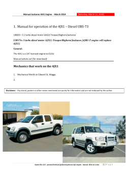
Subject: 4JX1 Manual of Fixes from Contributers Print:[Sunday, March 16, 2014] Manual for operation of the 4JX1 – Diesel UBS-73 UBS69 = 3.1 turbo diesel motor (4JG2) Trooper/Bighorn/Jackaroo UBS73= 3 turbo diesel motor (4JX1) Trooper/Bighorn/Jackaroo 4JB1-T engine will replace 4JX1 General: The 4JX1 is a CAT licenced engine to IZUSU Manual (whole car) [for download]: Mechanics that work on the 4JX1 1. Mechanical World on Edward St, Wagga. 2. _______________________________________________________________________________ 1|Page Subject: 4JX1 Manual of Fixes from Contributers Print:[Sunday, March 16, 2014] INDEX FOR 4JX1 1. OVERALL OPERATION OF THE 4JX1 ENGINE: 4 2. HOW THE 4JX1 SYSTEM WORKS: 5 DIAGNOSTIC GEAR - TECH – II 6 DIESEL INITIAL ANALYSIS 7 Diagnostics – Non Starting Engine: 8 Service Intervals [found by 4JX1 users] 10 5. PARTS LIST: 11 6. OIL CHANGES: 11 1.2. Notes on Oil related matters: 7. INJECTORS 11 12 1.3. Gaskets and seals needed to change the injectors 12 1.4. INJECTOR SEALS: 13 1.5. Injectors: 14 1.6. Cleaning intake manifold and replace the glow plugs: 14 8. WATER SYSTEM: 16 1.7. HEATER leaks [under Dash]: 16 1.8. Faulty “O” Ring rear head: 16 1.9. Water pump: 17 1.10. Sensors and Returns: 18 1.11. Multi plug connector: 18 9. ORPS [OIL RAIL PRESSURE SENSOR] 18 1.12. ECM - Engine Control Module 20 1.13. ECU – Electronic Control Unit 21 1.14. High pressure Pump: 21 1.15. PCV Valves: 21 2|Page Subject: 4JX1 Manual of Fixes from Contributers Print:[Sunday, March 16, 2014] 1.16. Oil Rail Pressure Meter 22 1.17. Starting after replacing injector O-rings: 23 10. HIGH PRESSURE PUMP AND O-RINGS 23 1.18. CPS - Crank Position Sensor: 24 1.19. TPS [Throttle Position Sensor] 24 1.20. Throttle Body and EGR: 24 1.21. Calibrating the TPS [Throttle Position Sensor] 25 TPS: 25 ECU and calibration of TPS: 27 3|Page Subject: 4JX1 Manual of Fixes from Contributers Print:[Sunday, March 16, 2014] 1. Overall operation of the 4JX1 Engine: Suggested Actions for Owners [Injector Article written by Red-one] • Ensure the correct type and grade of oil is being used in the engine. Correct operation of every part of the injector oil circuit is critical to the successful operation of this engine. The piston within the injector has to move exactly the correct distance to deliver the correct quantity of fuel, and operate at exactly the right moment in the engine cycle, for the engine to run correctly. Selection of a good quality oil, of suitable viscosity, clearly plays a vital part in this. • Check sump oil level regularly (at least once per week), and be aware that a rising oil level could be the start of other problems. • Keep a wary eye open for fluid loss or leaks such as oil leaks from engine seals, or the smell of diesel in the coolant. • Holden Jackaroo owners - contact Holden and enquire whether the Campaign 03-H-03 has been done on your vehicle. Note this Campaign relates to the injector sleeve sealing O-rings, which according Holden : “can deteriorate and cause fuel to leak into the crankcase”. If not, book it in – Holden should do this free of charge. • At each 80 k kms service interval, replace the O-rings between injectors and sleeves, and between sleeves and cylinder head, as a precaution. This will add little to the overall cost of the service, as the mechanic will already be working in this part of the engine, checking and adjusting the valve clearances. • If the oil level in the sump rises to the point that it enters the crankcase breather pipe, the engine may start to run on it’s own oil. In this situation, in Holdens words : “ this may result in an unintentional increase in engine speed, and possibly vehicle speed”. If this happened, it would cause most people to get very alarmed, especially if it happened in heavy traffic, driving at high speed, etc.. The engine will no longer respond to normal throttle operation, and will continue to run even with the ignition switched off. • In extreme cases, engines have been known to red-line and self destruct. In the UK, there have been cases of engines being replaced free of charge by Isuzu. • If a motorist is unfortunate enough to experience a run away engine, the best advice is to immediately steer in a safe direction, engage the highest possible gear and jump on the footbrake and hand brake together to stall the engine. Only depress the clutch or engage neutral as a last resort as this will allow the engine to spin freely out of control. This will be alien to most normal driving, and against normal instincts. Failure to stop the engine at this point may lead to a very expensive engine rebuild. Staying on a high traction surface eg bitumen would be better than driving onto loose sand – spinning wheels would have little braking effect on the engine. Do not turn off the ignition before the vehicle comes to rest, to avoid locking the steering wheel. 4|Page Subject: 4JX1 Manual of Fixes from Contributers Print:[Sunday, March 16, 2014] 2. How the 4JX1 System Works: 5|Page Subject: 4JX1 Manual of Fixes from Contributers Print:[Sunday, March 16, 2014] 3. Diagnostic gear - TECH – II I believe it is this card. http://www.uobd2.net/wholesale/32mb-card-for-gm-tech2-1538.html ISUZU ISUZU-English 107.021 2006-2010 ISUZU-CANBUS is for ISUZU after 2010 ISUZU-K-line is for ISUZU from 1996 to 2010 Request the K-Line software as this covers our Jackaroos. 6|Page Subject: 4JX1 Manual of Fixes from Contributers Print:[Sunday, March 16, 2014] 4. Diesel initial analysis 7|Page Subject: 4JX1 Manual of Fixes from Contributers Print:[Sunday, March 16, 2014] Diagnostics – Non Starting Engine: 8|Page Subject: 4JX1 Manual of Fixes from Contributers Print:[Sunday, March 16, 2014] 9|Page Subject: 4JX1 Manual of Fixes from Contributers Print:[Sunday, March 16, 2014] Service Intervals [found by 4JX1 users] Item Distance INJECTOR SEALS 100,000 CAT HEUI injectors for internal seal replacement 100,000 -150,000 Oil Changes 10 | P a g e Subject: 4JX1 Manual of Fixes from Contributers Print:[Sunday, March 16, 2014] 5. Parts List: OIL FILTERS Isuzu Ryco Cooper Wesfil/Nippon Max Main Oil Filter Part 8-97167-972-0 Z600 WZ554/ MO-024 Secondary Filter Z79A WZ79 * Air Filter A1081 WA1081 Out of all the above, the Wesfil products are not only the cheapest, but also seem best quality / suited to the Jackaroo. The main filter from them, appears to be almost identical in marking to the OEM, minus the Isuzu branding... Contact Neil @ Sydney Filter Service. He has all the Nippon Max and Wesfil Filters and is cheaper including the freight than what I can buy the lot locally. Just tell him you have the 4JX1 Jackaroo Diesel and he will do the rest. 6. OIL CHANGES: Most likely the wrong grade of oil was used. The oil must be 5W 30/40 (0W if in cold climates) else it wont start. Interestingly the 2 oils that are known to work well with this engine (Penrite HPR Diesel/5 and Mobil Delvac1). Both have the lowest pour points available from oils (around -48 degrees C) Notes on Oil related matters: The injectors are hydraulic? (correct me if I am wrong) and use the oil to operate. If there is not enough oil pressure, they don't fire. Pretty simple really. Many 4JX1 owners and myself use Penrite HPR 5 5W40 oil with Nippon Max filters which can be bought from Sydney Filters. Ryco filters have caused oil pressure issues for some people. Small oil filter meant to be changed every second service so 20,000km 11 | P a g e Subject: 4JX1 Manual of Fixes from Contributers Print:[Sunday, March 16, 2014] 7. Injectors The vehicles were sold in Australia by Holden (GM) as the Jackaroo. In Australia, these problems appear to be little understood by the general Holden dealer network. There has been a single campaign to replace injector sleeve sealing Orings, but no indication of replacing the injectors themselves. The relevant Campaign Notice is available at the Product Recalls Australia website : http://www.recalls.gov.au/view_recall_detail.php?Recall_ID_Auto=13023 Early injectors (up to Serial No. 519266) used a rubber O-ring material (green colour probably Viton) but later ones were fitted with ceramic seals instead. Whenever owners are having injectors replaced, they should ensure only later model injectors (ie after 519266) are fitted, as these will have the most recent ceramic seals. Based on extensive experience in the UK, my overseas contact advised that all injectors fitted to early vehicles up to about 2001 (ie those fitted with rubber O-rings prior to later ceramic seals) are likely to have a problem at some point, and would need to be replaced. From 2001 onwards, it seems if they are going to go, they fail early (say approx 30 k kms). Failure of the later model injectors (ceramic seals) appear to be very rare. Gaskets and seals needed to change the injectors Item Holden part numbers Number Notes gasket nozzle GM-8972407980 4 washers, 'o' rings, and seals gasket injector nozzle GM-8971757830 4 4 gasket injector nozzle GM-8971611092 4 4 gasket HP oil pipe GM-8971842160 gasket Throttle Body GM-8971378200 'Rocker cover gasket' EGR Port gasket GM# 97137811 or 897137811-1 between exhaust manifold and head Exhaust manifold gaskets EM3202 ACL (Aftermarket) Yes you can change the manifold gaskets without removing the turbo or dump pipe (and gaskets) from the manifold, if you want to be tight. Just need to undo a $5 exhaust flange gasket under the car and then put a slit in your new gasket for #3 cylinder only. The cut needs to go on the LOWER stud hole (from lower stud hole in gasket down-ways to the OUTSIDE of the gasket). This is because it was the only stud that the manifold did not come clear of. The cut will allow you to wrap the gasket around the stud. Mines not leaking! 12 | P a g e Subject: 4JX1 Manual of Fixes from Contributers Print:[Sunday, March 16, 2014] INJECTOR SEALS: Please be in injector seals and not the head! And 9 times out of ten it will be the injector seals. As I have said previously on this forum, this procedure should be in the maintenance manual for every 100 000km's for the 4JX1. Basically, get the M16 Dynabolt as long as you can. About 150mm from memory. I welded on about 200mm M16 threaded rod to the threaded end. Then tightened up the dynabolt in the sleeve and and used a 50x50 box section supported by some 4x2. Then used a nut & washer to screw it all up. Have a look through the forums and you will see some that others have done. Some say it may score the inner sleeve. I did not notice any marks inside, although am sure it is not the best method. (Cylinder 4 took a lot of attempts and it pulled out of the sleeve a few time) 13 | P a g e Subject: 4JX1 Manual of Fixes from Contributers Print:[Sunday, March 16, 2014] The removal tool would be the easiest & safest but there you go...... Remember to try to fill the oil rail up with oil before installing it back otherwise it takes a while to start. I did the oil rail pressure sensor and wiring loom while I was at it just for piece of mind and you are taking it all apart at the same time. (Not sure if you know about the dramas with these parts. If not, search the forum) The cost of all the items is not much and as it all came from Dubai, the transport costs made it all worthwhile. Holden do a service kit think sleeves are $80 each plus o-rings Injectors: Clicking indicates the solenoids are working. How well they're working is normally decided on a test rig. Alternatively, it's trial and error. The injector internal O-rings and springs also need to be sound. These 3 types of parts are replaced in a kit for the CAT HEUI injectors for 100,000 -150,000km services. Isuzu don't do a kit. When you removed the original injector, was there any discolouration between the bottom O-ring and the copper "gasket"? Update for anyone interested....I replaced seals on the 2nd hand injector and reinstalled it this evening...did all the usual things, double checked everything, soon as I got oil pressure up she fired up and sat there idling like it was brand new...no smoke. Took it for a run...beautiful. Starts easily. I now have 3 spare injectors with new seals. Total fix cost $100 for injector, $45 for seals. Thanks for advice and help. In measuring the HEUI internals, they seemed to have little wear in the metal parts. I would guess this is because they have light diesel fuel as well as heavier engine oil surging through their guts all the time. Also they're water cooled so remain at a constant temperature, rather than simply relying on the fuel temperature like in a standard common rail. This would indicate that the "reconditioned" injectors for sale have simply had new O-rings and springs fitted. The solenoid would have been checked if not rewound. The CAT HUEI overhaul set is: solenoid + o-rings + spring. Their kit sells for about A$65-85 per injector. Recommended interval between overhaul is 100,000km. This is why I am fiddling with it. The Isuzu injector is a direct scaled down copy of a CAT injector. Cleaning intake manifold and replace the glow plugs: I have not been happy with the performance since. Anyhow, I had the check engine light appear last night and was blowing some white smoke in the mornings until it reached operating temperature. ish. [1] White smoke implies you have not yet got 4 working Glow-Plugs. Did you check the resistance was within spec [0.8 1.2Ω] AFTER installing the new Plugs? They're all supposed to be attached to a strong little bus-bar. Is THAT broken in some place - or is there a good electrical-connection at the bulkhead-end? [2] DTC #16 does, indeed, indicate a faulty Oil-Temp-Sensor - but it MIGHT just be that you've damaged the connector. The sensor itself is pretty robust! It's the sensor beside the ORPS, on the HP-Oil-Rail. All of those connectors are subject to heat and vibration and sometimes the locking-clips break-off.....! Some folk have re-attached the connectors with Cable-Ties! 14 | P a g e Subject: 4JX1 Manual of Fixes from Contributers Print:[Sunday, March 16, 2014] [3] DTC #74 is our old pal, the TPS - which, again, might NOT be faulty. Whether with a new TPS or an old one, the output-voltage seen by the ECM [measured at J1-18] varies with the MOUNTING-ANGLE of the TPS on the side of the Throttle-Body. So, loosen the 2 mounting-bolts, set up the Voltmeter [between the ECM-connector-J1, pin J1-18 and Battery(-)] and turn the TPS until the voltage is about 0.85V - that's with the Ignition ON and the Engine OFF. It does NOT require a Tech2, as the voltage can be read directly from the ECM connectors. _________________________________________________________________________________________________ 15 | P a g e Subject: 4JX1 Manual of Fixes from Contributers Print:[Sunday, March 16, 2014] 8. Water System: HEATER leaks [under Dash]: Both pipes where the go into the heater matrix are plastic, see photo attached Did this job several months ago myself, yep time consuming s#*t of a job. I had to let the gas out of the air con to get the a/c box out to get to the heater element. Had to pull most of the dash apart to get at it because of where the heater sits and the way to get it out. All I can say further is have fun. I did find a radiator place in Canberra I think was the cheapest place to source a new core. I wasn't going to put a 2nd hand 1 in that could break as well soon down the track. After checking try Autoheat in Canberra. Ken Faulty “O” Ring rear head: Of one more explanation about o-rings at the sleeves and possible reason of their damage. It could be overheating. Not a big overheating, that comes before cracks in the head, but small regular overheating every time your start the cold engine. Place: The reason for this could be a faulty (or just old) O-ring at the L-shape metal coolant pipe, going from the block of the engine to the head. At the block side its flange is bolted by 2 bolts m10 size, and at the other side its just pressed in the head. This L-shape pipe is located under the air conditioner pump holder, about 100 mm long, about 15-18 mm in dia Reason: Due to temperature changes head and metal pipe are expanding and compressing the o-ring. After cooling down the rubber o-ring returns to initial shape. By the time rubber becomes like a plastic and water starts leaking out(sometimes invisible from outside) and the air starts coming in, creating an air bubble in the gallery of the head, around injectors and sleeves. When the engine is started it takes some time to fill up the gallery with coolant and all this time injectors are working heated from combustion chamber. Diagnostics: At the beginning stage Place the inner car heater temperature handle to max hot. Switch off the fan and radio. Start the engine and listen to the sounds near glovebox area. If you hear sounds like water murmuring that means the air bubble was there. Repeat the test next morning. At the escalated stage: Park a car with a warmed-up engine at an angle to the front. Front side should be lower than a back, in my case 150mm of difference was enough. Stop the motor and wait for 2-10 min, you will see coolant drops under the car coming out pretty fast. (--or just do a pressure test ---) 16 | P a g e Subject: 4JX1 Manual of Fixes from Contributers Print:[Sunday, March 16, 2014] How-to-fix: Take out aircon pump, aircon pump holder, belt tensioner. Unbolt L-shape pipe and pull it out. Replace the O-ring. App time about 3h cleaning everything under aircon pump included. That’s what I did yesterday after I got a spot of coolant under the car. A bit of measurements: Old o-ring dimensions. Inner D =20mm, Outer D~25, H=3.5mm I've tried to fit a replacement o-ring (from Bunnings) with Inner D=19 and Outer D=26 it was very hard and i decided not to force it in. A little bit smaller from the same plumbing o-ring kit ($2.50 for a lot of them :-) ) fits well. But few weeks later it will be replaced with a genuine one, of course. Or a vitton one, if I'll find an equal replacement and it will pass my tests Water pump: The water pump went a couple of years later at around 215,000km. That cost me $246.50 from SMS Diesel Spares here in Sydney. __________________________________________________________________________________ 17 | P a g e Subject: 4JX1 Manual of Fixes from Contributers Print:[Sunday, March 16, 2014] Sensors and Returns: Ok, after cutting THE [white] wire codes are: Fault Type Codes Inj #1 fault 51 Inj #2 fault 52 inj # 3 fault 53 Inj # 4 fault 54 ORP High Voltage 62 DTC P1196 = Rail pressure system high warning.. Oil system high warning. P0192 (Flash 63) Rail Pressure Sensor Low Voltage P0193 (Flash 63) Rail Pressure Sensor High Voltage Rail Pressure System Low Voltage DTC P1194 (Flash 61) Rail Pressure System High Voltage DTC P1195 (Flash 61) Multi plug connector: When the loom is unplugged, oil in the plug, means the harness is wicking, and the oil creates cross talk too and from the ECM, and its only going to get worse I would recommend changing the harness as well as the ORP's __________________________________________________________________________________ 9. ORPS [Oil Rail Pressure Sensor] Since the engine will run when the ORPS wire to the ECU is cut and you have replaced the ORPS it would appear that the ORPS is either not getting the correct 5V voltage or GND voltage to it. Can you do a flash code test to see if there are any of the following DTCs set? DTC P0192 (Flash 63) Rail Pressure Sensor Low Voltage DTC P0193 (Flash 63) Rail Pressure Sensor High Voltage DTC P1194 (Flash 61) Rail Pressure System Low Voltage DTC P1195 (Flash 61) Rail Pressure System High Voltage Flash code diagnostics can be used to read active codes and to determine if history codes are present but cannot be used to clear codes or read history codes. Flash code diagnostics is enabled by grounding by terminal 4 shorting to terminal 13 of the DLC connector with the ignition switch “ON”. Grounding terminal 4 of the DLC connector. (see douments below). Attached File Reading Flash Diagnostic Trouble Codes.pdf 70.49KB 2 downloads Attached File Rail pressure system low or high voltage.pdf 89.06KB 1 downloads 18 | P a g e Subject: 4JX1 Manual of Fixes from Contributers Print:[Sunday, March 16, 2014] Attached File Engine cranks but won't run.pdf 69.67KB 3 downloads Has anyone had their motors nearly run but just wont fire up ? When I cut the white wire (orps) it runs fine but as soon as I replace it she wont run just nearly gets there but wont go . I have replaces the orps , injector seals , tps . I tried to compression test it and broke 3 glow plugs so I took the head off removed the broken ones and fitted it back up . It has very small crack in the glow plug hole of 3 cylinders but i dont know if that would be causing my problem , as the compression is fine. When It runs I get 2.7 volts at the white wire (orps) - It doesn't blow any smoke . Hi Nathjack, Since the engine wil run when the ORPS wire to the ECU is cut and you have replaced the ORPS it would appear that the ORPS is eiher not getting the correct 5V voltage or GND voltage to it. Can you do a flash code test to see if there are any of the following DTCs set? DTC P0192 (Flash 63) Rail Pressure Sensor Low Voltage DTC P0193 (Flash 63) Rail Pressure Sensor High Voltage DTC P1194 (Flash 61) Rail Pressure System Low Voltage DTC P1195 (Flash 61) Rail Pressure System High Voltage Flash code diagnostics can be used to read active codes and to determine if history codes are present but cannot be used to clear codes or read history codes. Flash code diagnostics is enabled by grounding by terminal 4 shorting to terminal 13 of the DLC connector with the ignition switch “ON”. Grounding terminal 4 of the DLC connector. (see douments below). Cheers, JackDriver Attached File Reading Flash Diagnostic Trouble Codes.pdf 70.49KB 3 downloads Attached File Rail pressure system low or high voltage.pdf 89.06KB 2 downloads Attached File Engine cranks but won't run.pdf 69.67KB 4 downloads Hi Edco - You really have to examine CAREFULLY what Nathjack is saying! As you quoted "When I cut the white wire (orps) it runs fine but as soon as I replace it she wont run just nearly gets there but wont go!" The phrase "nearly gets there but wont go" actually points out that it's TRYING TO START - and NOT trying to CONTINUE to run!! In a later comment, he wrote "It continues to run after I plug it [the ORPS] back in" - which means the ORPS is OK and ALL would then be well if the ECM could successfully control the pressure in the Oil-Rail in proportion to the Pedal-position. It can't 'cos the ORPCV is NOT responding. Therein lies the BIG DIFFERENCE - When actually running, it'll plod along with barely enough pressure to fire the injectors - but at STARTUP - the ECM will 'forbid' the injectors to fire if the signal from the ORPS shows too low OilPressure. Cut the magic white wire and it'll go - but very badly - 'cos the REAL pressure is still too low! I pulled apart the orpcv it all appears ok gave it a good clean, put it back together and still no luck it still runs fine with the orps wire cut . When I stop the motor and plug the orps wire together it will try to start and just idle along very slowly with no throttle response. When its running I get between 2.7 volts at idle and 2.9 volts at 2000rpm from the white wire so to me it seems like the oil is being controlled fine and I am getting a signal back to the ecm . I have 5 volt supply to the orps , I will put a test light from the battery and check the earth circuit tomorrow . 19 | P a g e Subject: 4JX1 Manual of Fixes from Contributers Print:[Sunday, March 16, 2014] It is a cheap ebay orps as well!! Would be great if someone could check their voltage at the white orps wire. Nathjack ECM - Engine Control Module The ECM is the Engine Control Module - which is a fairly robust computer dedicated to managing the timing and length of the injection-stroke [fuel input] and the oil-pressure in the Rail [hydraulic power to the injectors] etc. You shouldn't mess with the ECM beyond making sure that all its connectors are clean [they can get oil seeping-into them!] and dry and making good solid electrical-connections. __________________________________________________________________________________ 20 | P a g e Subject: 4JX1 Manual of Fixes from Contributers Print:[Sunday, March 16, 2014] ECU – Electronic Control Unit At idle the ECU adjusts the Oil rail pressure control valve until it sees a voltage of approx. 1-volt from the ORPS. As you crack the throttle open the ECU gives a very short burst of full pressure injection where the ECU wants a voltage of around 4.6 volts until the boost starts to rise and the ECU cuts back the injection pressure to what is needed under its mapping program. At a constant 80 km/h on flat ground my car shows a voltage of approx. 2.4 volts. At a constant 100 km/h on flat groung it shows approx 3.0 volts. Under full throttle the ECU varies the pressure up to approx 4.6 volts depending on current boost etc--- High pressure Pump: Hi Mattsjack, Diesels like the 4JX1 do not generate vacuum from the inlet manifold, as this is mostly under positive pressure, not negative as in a petrol motor. Instead a diesel have a dedicated vacuum pump which, in the case of the 4JX1, lives under the high pressure oil pump and is driven directly from the timing gears. timing gear.jpg ISSUES: • Leaking injector tube seals • Faulty ORPS • Wrong engine oil type • Dodgy oil filter for the high-pressure supply side. PCV Valves: Injectors: It is also suggested you replace the copper washer every 100-150k it as in CAT HEUI diesels and 4JX1's in Russia as maintenance item. Saves time later down the track. 21 | P a g e Subject: 4JX1 Manual of Fixes from Contributers Print:[Sunday, March 16, 2014] Oil Rail Pressure Meter CTIs Oil Rail Pressure Meter is a diagnostic tool designed to verify the oil pressure in the injection system of Isuzu 4JX1 3.0 Litre Turbo Diesel engines. The Oil Rail Pressure Meter can be retro-fit to any existing vehicle using the 4JX1 motor in approximately 1 hour by someone with handyman skills. Rough idling, long starting crank cycles or your engine not starting are all tell tale signs that your Isuzu 4JX1 engine has compromised components in the hydraulic system. Our Oil Rail Pressure Meter can help in identifying which components are faulty or failing based on the oil pressure readings at different engine states. Under normal driving conditions the Oil Rail Pressure Meter readings should read between 1.00 and 3.50. Should the meter readings fall outside of these parameters (for normal driving and no noticeable change in performance) it is possible that the oil rail sensor is faulty. With a cold engine and the cam angle sensor disconnected, cranking the engine should give a reading above 1.20 (depending on oil temperature, battery condition, type and grade of oil used). Note that the engine will not start with the cam angle sensor disconnected. Under normal operation, if the Oil Rail Pressure Meter reading does not reach 1.00 the engine will not start. Likely causes are: • HEUI pump control voltage missing (reading should be approximately 10.00 or more) • Loose connection (oil leak) on an injector or associated hydraulics • Low oil in sump, and/or • Air leak in the pickup for the hydraulic priming pump If the Oil Rail Pressure Meter reading is above 1.00 the engine will not start. The problem is most likely associated with other ECU inputs: • Cam angle sensor • Crank angle sensor • Fuel pressure switch, and/or • Other electronics CTIs Oil Rail Pressure Meter can also be used as an economy fuel gauge for Isuzu 4JX1 engines by driving with oil pressure readings below 2.5. I think buying a Tech2 and reading the Isuzu manual is the correct translation. There are so many hoping to cash in on the fear of the 4JX1. It's a simple system. The oil that drives the injectors is held at the right pressure by the ORPS and the RPCV. The Oil Temp sensor is a bit of a fine tune for oil viscosity. The wiring harness needs a clean at 240,00km intervals. After that the ECM does all the work. Period. Change the sleeve seals and copper washers at the same intervals as a CAT diesel - 100,000km. Buy a Tech2 for $400 lousy bucks and learn to read it. Then be assured you have the same super reliable, super economical, super long lived Isuzu diesel as in all the trucks I’ve owned. 22 | P a g e Subject: 4JX1 Manual of Fixes from Contributers Print:[Sunday, March 16, 2014] Starting after replacing injector O-rings: You need a fully charged battery to get oil up into the common rail and at 400psi, + all the air out of the fuel lines. The Isuzu manual tells you straight that it will take a lot to start it if the oil rail isn't primed with 300cc of oil. When the diesel tries to start there's about 20A going to the glow plugs, about 15A going to the power transistors in the ECM, and about 25A going to the starter motor. I hope you bled the fuel lines properly.. after draining the tank to check for coolant in there. If the seals were leaking it could be full of water. :-) Did you pre-fill oil gallery before connecting injectors to it? Did you pre-fill oil filters before installation? What filters did you use? Genuine? Wiring loom is connected properly? Oil pressure gauge showing no oil pressure -which one? at the dash? or extra? Oil level is ok? Any MIL codes? Check that the o-rings have not caught when you put the sleeves in and dont have fuel in the coolant etc. Otherwise, as SergAnt says above, it takes a lot of oil to fill up again if you emptied all the system. I was cranking my engine for quite a while. (two battery charges from memory) The Jack LIVES. After reading through your questions sergey, i took everything apart, gave the wiring loom another thorough clean, reinstalled everything again and hey presto oil pressure on the dash and no cel =) 10. High pressure Pump and O-rings It turned out to be a good call. The small o-ring was totally shagged. The cost for parts was only $40 but labour was $840 which I thought was pretty good considering they had 2 guys on it all day to get access and compared to Holden that was going to charge approx. $1300 labour to do the job. If you're having problems with the HPOP or as diagnosed on Tech II lack of pressure (min 2.8 Mpa) to enable injectors, have a search on ITOCUK,for Oil Rail Control valve, known as ORPCV or ROPCV search posts by "Gribble" for a piccy step by step. ;) Obviously check ORPS first. 23 | P a g e Subject: 4JX1 Manual of Fixes from Contributers Print:[Sunday, March 16, 2014] CPS - Crank Position Sensor: Jack would just die, no running rough / coughing / farting, nothing. Just cut out. Intermittently.. I'd had a check engine light for some time with no associated code on the scan gauge, didn't seem to affect the running so ignored it.... The lack of motive power forced me to look into things a little more and after shorting the ODBC pins, I got the code for the throttle position sensor. No probs, quick call to Kumbak and the new (to me) sensor is fitted, code gone, and a quick spin down the back paddock proves it's all fixed. Not! Thinking all was good, I headed into town to pick the kids up from school. I made it half way before she stopped again. Towed home behind the wife’s Dunny door, not real embarrassing! About another week of diagnosing the problem, ruling out all the usual suspects and I finally happened on a tip on the UK Isuzu website which mentioned the crank position sensor. I pulled the sensor and what do you know, it was covered in mud and crap! Surely it can't be this simple.... Cleaned the sensor and reinstalled it. The workshop manual mentions an oring, which there was no sign of when I removed the sensor....I found one roughly the right size in the shed and fitted that. Good find, not sure if your scan gauge will tell you, but if the CPS is dead the RPM as shown on the scanner while cranking will be half of actual. That is it seems to be cranking at normal speed (220~240) but shows around 120RPM. TPS [Throttle Position Sensor] [3] DTC #74 is our old pal, the TPS - which, again, might NOT be faulty. Whether with a new TPS or an old one, the output-voltage seen by the ECM [measured at J1-18] varies with the MOUNTING-ANGLE of the TPS on the side of the Throttle-Body. So, loosen the 2 mounting-bolts, set up the Voltmeter [between the ECM-connectorJ1, pin J1-18 and Battery(-)] and turn the TPS until the voltage is about 0.85V - that's with the Ignition ON and the Engine OFF. It does NOT require a Tech2, as the voltage can be read directly from the ECM connectors. I think what Browndoff means to say is use a Tech 2! Then using the Throttle Position Motor program, check the TPS voltages at each step against the chart below. The TPS might be OK, but just way out of alignment or in need of a clean with some contact cleaner. Throttle Body and EGR: How can the throttle get dirty from oil AND EGR if the EGR is AFTER the throttle plate?? We have had the discussion about disabling the EGR before and the conclusion is the ECM in the 4JX1 uses the throttle and EGR to increase efficiency not the other way round like most people wrongly believe! The EGR also is used to reduce the combustion temp by about 500 degrees by reducing the amount of oxygen in the air as you said which is a good reason not to disable it. This extra 500° could also cause the injector sleeve seals and injector gaskets (copper washer under the injector) to fail prematurely thus causing more trouble than good. Also, if you disable the EGR we won't ALL live happily ever after. You won't be happy after receiving a fine or yellow sticker for disabling the emissions reduction system and the tree huggers won't be happy either! 24 | P a g e Subject: 4JX1 Manual of Fixes from Contributers Print:[Sunday, March 16, 2014] Easy solution to keeping the intake throttle clean is to use a catch can on the breather hose. No more oil into the intake = clean throttle plate and cleaner intake manifold. If you use a EGR filter\soot catch can thingo (they do actually exist!) you will then reduce the soot in the intake and the intake manifold will be nice and clean. No oil or soot. Problem solved! Calibrating the TPS [Throttle Position Sensor] [http://forum.australia4wd.com/index.php?/topic/28024-tps-adjustment-procedure/?p=196608] for full description and comprehensive images] I've had the throttle body off a few times for various reasons and I thought I'd share with you my procedure for calibrating the TPS. As SergAnt and other gurus will tell you it's important that the TPS is calibrated correctly otherwise engine power and fuel consumption can be adversely affected. Use of Tech2. With this baby you can run a throttle position sensor test where you can step through all the throttle positions from 0 through to 10 and display the TPS voltage. TPS: The adjustment procedure that I recommend is as follows: 1. Remove intercooler cover. 2. Loosen the clamps on the pressure hose between the intercooler and the throttle body. 3. Remove the intercooler mounting bolts. No need to remove all four, just the two on the throttle body side will suffice. 4. Remove the pressure hose between the intercooler and the throttle body. 5. Remove the intercooler bracket that is attached to the throttle body. 6. Remove throttle body assembly, take off stepper motor and TPS. Make sure that you don't lose the small section O-ring that seals the TPS to the throttle body. 7. Clean the throttle body with good quality carby cleaner. It's important that you take the stepper motor and TPS off before you use the carby cleaner as it's an aggressive cleaning agent and could easily damage them. 25 | P a g e Subject: 4JX1 Manual of Fixes from Contributers Print:[Sunday, March 16, 2014] Attached File Throttle body components.jpg 90.76KB 1 downloads 8. After cleaning, and before reinstalling the stepper motor and TPS, ensure that the throttle blade moves freely throughout its entire travel without binding and that the return spring moves the blade back to wide open without hesitation. Attached File Maximum blade angle adjustment screw.jpg 83.79KB 1 downloads 9. Clean the O-rings that seal the stepper motor and TPS with a clean lint free rag then mount the stepper motor and TPS back on the throttle body. Nip the mounting screws up just a bit but leave them loose enough so that you can rotate the stepper motor and TPS against the throttle body. 10. Loosen the jam nut on the small allen head screw which determines the maximum blade angle and loosen the screw. This needs to be loosen to ensure that the stepper can move the throttle blade to its maximum extent. Attached File Throttle body components.jpg 90.76KB 1 downloads 11. While I've found that you can adjust the TPS with the throttle body installed on the manifold, it's much easier to adjust everything with the throttle body connected but just sitting on the manifold as shown in this image Attached File Testing before reinstalling.jpg 75.55KB 3 downloads 12. Disconnect the glow plug wiring harness as shown. This will reduce battery drain while you adjust the stepper motor and TPS positions. Attached File Disconnect glow plugs.jpg 60.03KB 3 downloads 13. Turn on the ignition without engaging the starter, power up the Tech2, go to the Miscellaneous Test menu and select Throttle Position Motor. 14. Scroll down the data display until you see TPS voltage above the Throttle Position at the bottom of the display. 15. Use the �Decrease’ soft key to get the stepper motor to zero steps if it isn’t already there then rotate the TPS until the TPS voltage is as close to 0.50V as you can get. The allowable voltage range is 0.44V to 0.56V. Attached File Tech2 showing motor steps & TPS voltage.jpg 78.24KB 2 downloads 16. Tighten the TPS mounting screws and ensure that the TPS voltage has not changed. 17. Use the �Increase’ soft key to advance the stepper motor to 1 step, then rotate the stepper motor until the TPS voltage is as close to 0.84V as you can get. The allowable voltage range is 0.75V to 0.95V. 18. Go through all the stepper motor positions and record the TPS voltage for each step. The allowable voltage values are in the table below. Attached File TPS values.png 26.03KB 1 downloads 19. Repeat step 18 a number of times to see if the TPS voltage remains the same each time. Note that the allowable voltage variation is by +/- 0.02V between runs. 20. With the stepper motor at step 1, tighten the stepper motor mounting screws and ensure that the TPS voltage doesn't change. 21. Select zero steps, unscrew the allen head screw then push the throttle blade until it contacts the throttle body. Next, screw in the allen head screw until the throttle blade starts to move away from the throttle body. Note the 26 | P a g e Subject: 4JX1 Manual of Fixes from Contributers Print:[Sunday, March 16, 2014] voltage on the Tech2 - it should be higher than was achieved at step 10. When shutting down the engine, the ECU commands to stepper motor to step 11, which I presume is to fully close the air intake to gently stop the engine. 22. Retighten the jam nut and recheck that the TPS voltage at 10 steps has not changed. 23. Power off the Tech2 and turn off the ignition. 24. Disconnect the stepper motor and TPS wiring and reinstall the throttle body using new gaskets. 25. Reconnect the stepper motor and TPS wiring. Retighten the stepper motor and TPS mounting screws 26. Reinstall the intercooler bracket that bolts to the throttle body. 27. Reinstall the pressure hose between the intercooler and the throttle body. 28. Tighten the intercooler mounting bolts. 29. Tighten the clamps on the pressure hose between the intercooler and the throttle body. 30. Replace intercooler cover. 31. Reconnect the glow plug wiring. 32. Start the engine and re-run the Throttle Position Motor test on the Tech2 as a final confirmation. ECU and calibration of TPS: When I replaced my first TPS I checked it out with a multimeter and found that it gave correct values at either end of its travel but gave inconsistent readings in the middle of its travel. From what I have observed while freeway driving around with Tech2 attached is that the stepper motor spends a lot of its time in the middle sectors, around 4~7 steps which is exactly where it was giving inconsistent readings. So to recap. 1. It may be possible to use a multimeter to diagnose a fauly TPS 2. It is possible for a known good TPS to be calibrated to produce the correct voltage at zero steps by using a simple multimeter. 3. It is not possible to calibrate the stepper motor without being able to get it to move from zero steps to a known step, whether that step be 1, 2, or any any number up to 10. 4. If the stepper motor is not calibrated then the ECU will not be able to position the throttle blade accurately even though the TPS is correctly calibrated. 27 | P a g e
© Copyright 2026 Paperzz