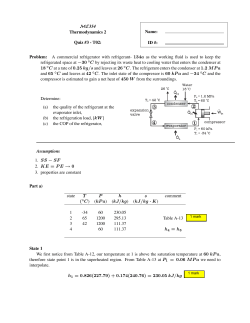
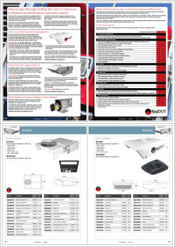
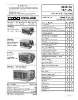
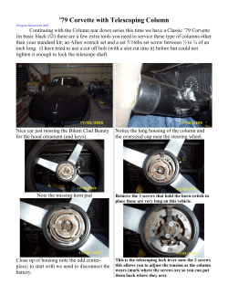
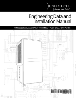
INSTALLATION INSTRUCTIONS Litho U.S.A. E2014 WARNING Improper installation, adjustment, alteration, ser vice or maintenance can cause property damage, personal injury or loss of life. Installation and ser vice must be performed by a qualified installer, ser vice agency or the gas supplier Table of Contents Dimensions . . . . . . . . . . . . . . . . . . . . . . . . . . . . . . . . . Parts Arrangements . . . . . . . . . . . . . . . . . . . . . . . . . Shipping and Packing List . . . . . . . . . . . . . . . . . . . . General . . . . . . . . . . . . . . . . . . . . . . . . . . . . . . . . . . . . Unit Support . . . . . . . . . . . . . . . . . . . . . . . . . . . . . . . . Duct Connection . . . . . . . . . . . . . . . . . . . . . . . . . . . . Rigging Unit For Lifting . . . . . . . . . . . . . . . . . . . . . . . Condensate Drains . . . . . . . . . . . . . . . . . . . . . . . . . . Gas Piping . . . . . . . . . . . . . . . . . . . . . . . . . . . . . . . . . Pressure Test Gas Piping . . . . . . . . . . . . . . . . . . . . . High Altitude Derate . . . . . . . . . . . . . . . . . . . . . . . . . Electrical Connections . . . . . . . . . . . . . . . . . . . . . . . Blower Operation and Adjustments . . . . . . . . . . . . Page 2 Page 5 Page 6 Page 6 Page 7 Page 8 Page 8 Page 8 Page 8 Page 9 Page 10 Page 10 Page 12 LGH/LCH156H LGH/LCH180H LGH/LCH210H LGH/LCH240H LGH/LCH300S (13 Ton) (15 Ton) (17.5 Ton) (20 Ton) (25 Ton) ROOFTOP PACKAGED UNITS 507124-01 6/2014 Supersedes 10/2012 Cooling Start-Up . . . . . . . . . . . . . . . . . . . . . . . . . . . . Gas Heat Start-Up . . . . . . . . . . . . . . . . . . . . . . . . . . . Heating Operation and Adjustments . . . . . . . . . . . . Electric Heat Start-Up . . . . . . . . . . . . . . . . . . . . . . . . Supply Air Inverter Start-Up . . . . . . . . . . . . . . . . . . . Supply Air Inverter Operation . . . . . . . . . . . . . . . . . Hot Gas Reheat Operation and Start-Up . . . . . . . . Service . . . . . . . . . . . . . . . . . . . . . . . . . . . . . . . . . . . . ECTO Settings . . . . . . . . . . . . . . . . . . . . . . . . . . . . . . Page 19 Page 37 Page 39 Page 39 Page 40 Page 42 Page 43 Page 48 Page 50 RETAIN THESE INSTRUCTIONS FOR FUTURE REFERENCE LGH180 SHOWN 06/14 *2P0614* 507124-01 *P507124-01* LGH/LCH156 Unit Dimensions - Inches (mm) - Gas Heat Section Shown 107−3/4(2737) BASE 4−1/4 (108) 12−3/8 (314) 28−3/8 (721) ALTERNATE (THRU THE BASE) CONDENSATE DRAIN LOCATION 5−5/8 (143) 1−5/8 in. (41 mm) Diameter 18 (457) 12−3/8 (314) 60−1/2 (1537) BOTTOM RETURN AIR OPENING 15 (381) BOTTOM SUPPLY AIR OPENINGS 28 (711) 20 (508) 4−1/2 (114) 91−1/8 (2315) BASE 28 (711) 20 (508) CENTER OF GRAVITY 4 (102) 4 (102) BOTTOM POWER ENTRY 5 X 8 inches (127 X 203 mm) TOP VIEW 90−1/8 (2289) OPTIONAL DISCONNECT (Factory Installed) 106−1/2 (2705) OPTIONAL 115 VOLT OUTLET (Factory Installed Inside Unit) 51 (1295) GAS SUPPLY INLET CONDENSATE DRAIN SIDE ELECTRICAL 5−3/8 INLETS (137) 28−3/4 (730) GAS SUPPLY OUTLET (For Bottom Gas Supply Only) 91−1/8 (2315) BASE 4 (102) 54−1/4 (1378) 54−1/4 (1378) 10−1/4 (260) 8−1/4 (210) LIFTING HOLES (For Rigging Front and Back) 3−1/4 (83) FORKLIFT SLOTS (Front and Left Side Only) 107−3/4(2737) BASE SIDE VIEW END VIEW Page 2 LGH/LCH156, 180, 210, 240, 300S FLUE OUT LET LGH/LCH180 Unit Dimensions - Inches (mm) - Gas Heat Section Shown 133−1/8 (3394) BB AA 4−1/4 (108) 28−3/8 (721) 12−3/8 (314) ALTERNATE (THRU THE BASE) CONDENSATE DRAIN LOCATION 1−5/8 in. (41 mm) Diameter 5−5/8 (143) 12−3/8 (314) 60−1/2 (1537) BOTTOM RETURN AIR OPENING BOTTOM SUPPLY 18 (457) AIR OPENINGS 15 (381) 4−1/2 (114) 28 (711) 20 (508) 91−1/8 (2315) 28 (711) 20 (508) 4 (102) CENTER OF GRAVITY CC DD 4 (102) BOTTOM POWER ENTRY 5 X 8 inches (127 X 203 mm) TOP VIEW 90−1/8 (2289) GAS SUPPLY INLET CONDENSATE DRAIN SIDE ELECTRICAL 5−3/8 INLETS (137) 28−3/4 (730 ) GAS SUPPLY OUTLET (For Bottom 91−1/8 (2315) Gas Supply Only) OPTIONAL DISCONNECT (Factory Installed) 132−5/8 (3369) OPTIONAL 115 VOLT OUTLET (Factory Installed Inside Unit) 51 (1295) 4 (102) 10−1/4 (260) 54−1/4 (1378) FLUE OUT LET 54−1/4 (1378) 8−1/4 (210) 3−1/4 (83) LIFTINGHOLES (For Rigging Front and Back) BASE END VIEW FORKLIFT SLOTS (Front and Left Side Only) 107−3/4 (2737) BASE 25−3/8 (645) SIDE VIEW Page 3 507124-01 6/2014 LGH/LCH210, 240 & 300S Unit Dimensions - Inches (mm) - Gas Heat Section Shown 133−1/8 (3381) BB AA 4−1/4 (108) 12−3/8 (314) 28−3/8 (721) 60−1/2 (1537) 15 (381) BOTTOM RETURN AIR OPENING Y BOTTOM SUPPL AIR OPENINGS 18 (457) ALTERNATE (THRU THE BASE) CONDENSATE DRAIN LOCATION 1−5/8 in. (41 mm) Diameter 5−5/8 (143) 12−3/8 (314) 28 (711) 20 (508) 4−1/2 (114) 91−1/8 (2315) 28 (711) 20 (508) CENTER OF GRAVITY 4 (102) CC DD 4 (102) BOTTOM POWER ENTRY 5 X 8 inches (127 X 203 mm) TOP VIEW 90−1/8 (2289) OPTIONAL DISCONNECT (Factory Installed) 132−5/8 (3369) OPTIONAL 115 VOLT OUTLET (Factory Installed Inside Unit) 51 (1295) GAS SUPPLY INLET CONDENSATE DRAIN 28−3/4 (730) SIDE ELECTRICAL 5−3/8 INLETS (137) GAS SUPPLY OUTLET (For Bottom Gas Supply Only) 91−1/8 (2315) BASE 4 (102) 54−1/4 (1378) 10−1/4 (260) 8−1/4 (210) 3−1/4 (83) LIFTINGHOLES (For Rigging Front and Back) FORKLIFT SLOTS (Front and Left Side Only) 107−3/4(2737) BASE END VIEW SIDE VIEW Page 4 LGH/LCH156, 180, 210, 240, 300S 54−1/4 (1378) FLUE OUT LET 25−3/8 (645) LGH156, 180, 210, 240, 300S PARTS ARRANGEMENT ECONOMIZER DAMPERS (OPTIONAL) FILTERS (SIX - 24 X 24 X 2”) CONDENSER FANS (3 FANS ON 156 UNITS; 6 FANS ON 210, 240, & 300S UNITS EVAPORATOR COIL BLOWERS UNIT CONTROLLER INVERTER (OPTIONAL) CONDENSER COILS CONDENSATE DRAIN DISCONNECT COMPRESSORS (4 ON 240 & 300S UNITS) (Factory-installed option) GAS VALVE COMBUSTION AIR INDUCER BURNERS CONDENSER FANS (3 FANS ON 156 UNITS; 6 FANS ON 210, 240, & 300S UNITS LCH156, 180, 210, 240, 300S PARTS ARRANGEMENT ECONOMIZER DAMPERS (OPTIONAL) FILTERS (SIX - 24 X 24 X 2”) EVAPORATOR COIL BLOWERS UNIT CONTROLLER INVERTER (OPTIONAL) CONDENSER COILS CONDENSATE DRAIN DISCONNECT COMPRESSORS (4 ON 240 & 300S UNITS) (Factory-installed option) ELECTRIC HEAT Page 5 507124-01 6/2014 Shipping and Packing List Package 1 of 1 contains: 1- Assembled unit Check unit for shipping damage. Receiving party should contact last carrier immediately if shipping damage is found. IMPORTANT - Hot gas reheat units require a specific field-provided and installed humidity sensor. CAUTION Danger of sharp metallic edges. Can cause injury. Take care when servicing unit to avoid accidental contact with sharp edges. Requirements See figure 1 for unit clearances. General These instructions are intended as a general guide and do not supersede local codes in any way. Authorities having jurisdiction should be consulted before installation. UNIT CLEARANCES 180 UNIT SHOWN Optional Outdoor Air Hood The LGH156 gas/electric packaged rooftop unit is available in 260,000 & 360,000 Btuh heating input. The LGH180, 210, 240, & 300S gas/electric packaged rooftop units are available in 260,000, 360,000, or 480,000 Btuh heating inputs. The LCH156, 180, 210, 240, & 300S cooling packaged rooftop unit is the same basic design as the LGH unit except for the heating section. Optional electric heat is factory- or field-installed in LCH units. D B LGH and LCH units have identical refrigerant circuits with respective 13, 15, 17‐1/2, 20 and 25 ton cooling capacities. 156, 180 and 210 units contain three compressors; 240 and 300S units contain four compressors. Units come standard with a lightweight, all-aluminum condenser coil. Units are available with an optional, traditional fin/tube condenser coil. In addition to normal heating and cooling, hot gas reheat units provide a dehumidifying mode of operation. Refer to Reheat Operation section. Units equipped with an optional supply air inverter are available. The blower will operate at lower speeds when demand is low and increase to higher speeds when demand is high. Refer to Inverter Start-Up section. Units use R410A, an ozone-friendly HFC refrigerant. Refer to the Cooling Start-Up section for precautions when installing unit. WARNING Electric shock hazard and danger of explosion. Can cause injury, death or product or property damage. Turn off gas and electrical power to unit before performing any maintenance or servicing operations on the unit. Follow lighting instructions attached to unit when putting unit back into operation and after service or maintenance. Page 6 LGH/LCH156, 180, 210, 240, 300S C A FIGURE 1 1Unit Clearance A in.(mm) B in.(mm) C in.(mm) D in.(mm) Top Clearance Service Clearance 60 (1524) 36 (914) 36 (914) 66 (1676) Unob structed Clearance to Combus tibles 36 (914) 1 (25) 1 (25) 1 (25) Unob structed Minimum Operation Clearance 36 (914) 36 (914) 36 (914) 41 (1041) Unob structed Note - Entire perimeter of unit base requires support when elevated above mounting surface. 1 Service Clearance - Required for removal of serviceable parts. Clearance to Combustibles - Required clearance to combustible material (gas units). Minimum Operation Clearance - Required clearance for proper unit operation. NOTICE Roof Damage! This system contains both refrigerant and oil. Some rubber roofing material may absorb oil, causing the rubber to swell. Bubbles in the rubber roofing material can cause leaks. Protect the roof surface to avoid exposure to refrigerant and oil during service and installation. Failure to follow this notice could result in damage to roof surface. Use of this unit as a construction heater or air conditioner is not recommended during any phase of construction. Very low return air temperatures, harmful vapors and operation of the unit with clogged or misplaced filters will damage the unit. A-Downflow Discharge Application Roof Mounting with LARMF18/36 1- The LARMF roof mounting frame must be installed, flashed and sealed in accordance with the instructions provided with the frame. If this unit has been used for heating or cooling of buildings or structures under construction, the following conditions must be met or the warranty will be void: 2- The LARMF roof mounting frame should be square and level to 1/16” per linear foot (5mm per linear meter) in any direction. S The vent hood must be installed per these installation instructions. 3- Duct must be attached to the roof mounting frame and not to the unit; supply and return plenums must be installed before setting the unit. S A room thermostat must control the unit. The use of fixed jumpers that will provide continuous heating or cooling is not allowed. S A pre-filter must be installed at the entry to the return air duct. S The return air duct must be provided and sealed to the unit. S Return air temperature range between 55°F (13°C) and 80°F (27°C) must be maintained. S Air filters must be replaced and pre-filters must be removed upon construction completion. S The input rate and temperature rise must be set per the unit rating plate. S The heat exchanger, components, duct system, air filters and evaporator coil must be thoroughly cleaned following final construction clean-up. S The unit operating conditions (including airflow, cooling operation, ignition, input rate, temperature rise and venting) must be verified according to these installation instructions. IMPORTANT Installer's Roof Mounting Frame Many types of roof frames can be used to install the unit depending upon different roof structures. Items to keep in mind when using the building frame or supports are: 1- The base is fully enclosed and insulated, so an enclosed frame is not required. 2- The frames or supports must be constructed with non-combustible materials and should be square and level to 1/16” per linear foot (5mm per linear meter) in any direction. 3- Frame or supports must be high enough to prevent any form of moisture from entering unit. Recommended minimum frame height is 14” (356mm). 4- Duct must be attached to the roof mounting frame and not to the unit. Supply and return plenums must be installed before setting the unit. 5- Units require support along all four sides of unit base. Supports must be constructed of steel or suitably treated wood materials. NOTE-When installing a unit on a combustible surface for downflow discharge applications, an LARMF18/36 roof mounting frame is required. B-Horizontal Discharge Applications The Clean Air Act of 1990 bans the intentional vent ing of refrigerant (CFC's and HCFC's) as of July 1, 1992. Approved methods of recovery, recycling or reclaiming must be followed. Fines and/or incar ceration may be levied for non-compliance. 1- Units installed in horizontal airflow applications must use an LARMFH18/24 horizontal roof mounting frame. The supply air duct connects to the horizontal supply air opening on the LARMFH18/24. The return air duct connects to the unit horizontal return air opening. Refer to unit dimensions. Unit Support 2- Specified installation clearances must be maintained when installing units. Refer to figure 1. In downflow discharge installations, install the unit on a non-combustible surface only. Unit may be installed on combustible surfaces when used in horizontal discharge applications or in downflow discharge applications when installed on an LARMF18/36 roof mounting frame. 3- Top of support slab should be approximately 4” (102mm) above the finished grade and located so no run-off water from higher ground can collect around the unit. 4- Units require support along all four sides of unit base. Supports must be constructed of steel or suitably treated wood materials. NOTE - Securely fasten roof frame to roof per local codes. Page 7 507124-01 6/2014 Duct Connection All exterior ducts, joints and openings in roof or building walls must be insulated and weather-proofed with flashing and sealing compounds in accordance with applicable codes. Any duct passing through an unconditioned space must be insulated. and a maximum of 10.5” (2.60kPa) w.c. For LP/propane gas units, operating pressure at the unit gas connection must be a minimum of 11” w.c. (2.74kPa) and a maximum of 13.5” w.c. (3.36kPa). RIGGING Unit CAUTION In downflow applications, do not drill or punch holes in base of unit. Leaking in roof may occur if unit base is punctured. Rigging Unit For Lifting Rig unit for lifting by attaching four cables to holes in unit base rail. See figure 2. *Weight Kg. Lbs. LG 156, LC 156, LC 180 2350 LG 180, LG 210, LC 210, LC 240 LC 300 1066 2635 1195 LG 240, LG300 2780 1261 *Maximum weight with all available factoryinstalled accessories. LIFTING POINT SHOULD BE DIRECTLY ABOVE CENTER OF GRAVITY 1- Detach wooden base protection before rigging. IMPORTANT - ALL PANELS MUST BE IN PLACE FOR RIGGING. 2- Connect rigging to the unit base using both holes in each corner. 3- All panels must be in place for rigging. 4- Place field‐provided H‐style pick in place just above top edge of unit. Frame must be of adequate strength and length. (H-style pick prevents damage to unit.) Condensate Drains Remove cap and make drain connection to the 1” N.P.T. drain coupling provided on unit. A trap must be installed between drain connection and an open vent for proper condensate removal. See figure 3. It is sometimes acceptable to drain condensate onto the roof or grade; however, a tee should be fitted to the trap to direct condensate downward. The condensate line must be vented. Check local codes concerning condensate disposal. Refer to pages 2, 3 and 4 for condensate drain location. Note - The drain pan is made with a glass reinforced engineered plastic capable of withstanding typical joint torque but can be damaged with excessive force. Tighten pipe nipple hand tight and turn an additional quarter turn. Connect Gas Piping Before connecting piping, check with gas company or authorities having jurisdiction for local code requirements. When installing gas supply piping, length of run from gas meter must be considered in determining pipe size for 0.5” w.c. (.12kPa) maximum pressure drop. Do not use supply pipe smaller than unit gas connection. For natural gas units, operating pressure at the unit gas connection must be a minimum of 4.7” w.c. (1.17kPa) Page 8 LGH/LCH156, 180, 210, 240, 300S CAUTION - Do not walk on unit. FIGURE 2 CONDENSATE DRAIN CONNECTION NOTE - Allow clearance to open doors when installing condensate piping. CAULK AROUND CONDENSATE COUPLING UNIT Minimum Pitch 1” (25 mm) per 10' (3 m) of line Á Á Á Á OPEN VENT MOUNTING FRAME FIGURE 3 When making piping connections a drip leg should be installed on vertical pipe runs to serve as a trap for sediment or condensate. A 1/8” N.P.T. plugged tap is located on gas valve for test gauge connection. Refer to Heating Start-Up section for tap location. Install a ground joint union between the gas control manifold and the main manual shut-off valve. See figure 4 for gas supply piping entering outside the unit. See figure 5 for gas supply entering through bottom of unit. BOTTOM ENTRY GAS PIPING TO GAS VALVE GROUND JOINT UNION Compounds used on threaded joints of gas piping shall be resistant to the action of liquified petroleum gases. MANUAL MAIN SHUT-OFF VALVE Pressure Test Gas Piping When pressure testing gas lines, the gas valve must be disconnected and isolated. Gas valves can be damaged if subjected to more than 0.5 psig (3.48kPa). See figure 6. NOTE-Codes may require that manual main shut-off valve and union (furnished by installer) be installed in gas line external to unit. Union must be of the ground joint type. EXISTING SUPPLY DRIP LEG CAP FIGURE 5 After all connections have been made, check all piping connections for gas leaks. Also check existing unit gas connections up to the gas valve; loosening may occur during installation. Use a leak detection solution or other preferred means. Do not use matches candles or other sources of ignition to check for gas leaks. PRESSURE TEST GAS LINE MANUAL MAIN NOTE-In case emergency shut down is required, turn off the main manual shut-off valve and disconnect main power to unit. These devices should be properly labeled by the installer. SHUT-OFF VALVE OUTSIDE OF UNIT GAS PIPING TO GAS VALVE GAS VALVE FIGURE 6 GROUND JOINT UNION CAUTION MANUAL MAIN SHUT-OFF VALVE Some soaps used for leak detection are corrosive to certain metals. Carefully rinse piping thoroughly after leak test has been completed. Do not use matches, candles, flame or othe sources of ignition to check for gas leaks. TO GAS SUPPLY (REFER TO LOCAL CODES) CAP WARNING GAS PIPING SUPPORT DRIP LEG Danger of explosion. Can cause injury or product or property damage. Do not use matches, candles, flame or other sources of ignition to check for leaks. FIGURE 4 Page 9 507124-01 6/2014 B-Wire Routing High Altitude Derate Locate the high altitude conversion sticker in the unit literature bag. Fill out the conversion sticker and affix next to the unit nameplate. Refer to table 1 for high altitude adjustments. TABLE 1 HIGH ALTITUDE DERATE Altitude Ft.* 2000-4500 4500 And Above Gas Manifold Pressure See Unit Nameplate Derate 2% / 1000 Ft. Above Sea Level *Units installed at 0-2000 feet do not need to be modified. Route thermostat cable or wires from subbase through knockout provided in unit. Use 18 AWG wire for all applications using remotely installed electro-mechanical and electronic thermostats. On hot gas reheat units, route wires from RH sensor or remote switch through knockout provided in unit. For sensor installations, use 22AWG stranded, two twisted pairs, individually shielded, 100% aluminum shield with drain wire and Teflon jacket. IMPORTANT - Unless field thermostat wires are rated for maximum unit voltage, they must be routed away from line voltage wiring. NOTE ‐ This is the only permissible derate for these units. C-Wire Connections Electrical Connections POWER SUPPLY Do not apply power or close disconnect switch until installation is complete. Refer to start-up directions. Refer closely to unit wiring diagram. The Unit Controller will operate the unit from a thermostat or zone sensor based on the System Mode. The default System Mode is the thermostat mode. Refer to the Unit Controller Installation and Setup Guide to change the System Mode. Use the menu navigation arrows and select button; see Settings - Install. Refer to unit nameplate for minimum circuit ampacity and maximum fuse size. 1- Default Thermostat Mode The Unit Controller will operate two stages of heating and cooling based on thermostat demands. Install thermostat assembly in accordance with instructions provided with thermostat. See figure 7 for field wiring and and refer to wiring diagrams on unit. IMPORTANT-Terminal connections at the wall plate or subbase must be made securely. Loose control wire connections may result in intermittent operation. 2- Route power through the bottom power entry area and connect to line side of unit disconnect, circuit breaker or terminal block. See unit wiring diagram. FIELD WIRING WITH ELECTRONIC AND ELECTRO-MECHANICAL THERMOSTATS (Thermostat Mode) 3- Units With Optional 120v GFCI Outlet Route and connect separate 120v wiring to GFCI outlets which do not have factory-installed wiring. CONTROL WIRING A-Thermostat Location Room thermostat mounts vertically on a standard 2” X 4” handy box or on any non-conductive flat surface. Locate thermostat approximately 5 feet (1524mm) above the floor in an area with good air circulation at average temperature. Avoid locating the room thermostat where it might be affected by: -drafts or dead spots behind doors and in corners -hot or cold air from ducts -radiant heat from sun or appliances -concealed pipes and chimneys Page 10 LGH/LCH156, 180, 210, 240, 300S 24 V POWER R J297A P297 1 A55 P262 J262C 1- Units are factory-wired for 240/460/575 volt supply. For 208V supply, remove the insulated terminal cover from the 208V terminal on the control transformer. Move the wire from the transformer 240V terminal to the 208V terminal. Place the insulated terminal cover on the unused 240V terminal. 10 2 C B 11 G 3 W1 4 W1 W2 5 W2 Y1 6 Y2 7 12 8 OCP C 9 10 FIGURE 7 2- Zone Sensor Mode The Unit Controller will operate heating and cooling based on the Unit Controller internal setpoints and the temperature from the A2 zone sensor. An optional Network Control Panel (NCP) can also be used to provide setpoints. A thermostat or return air sensor can be used as a back-up mode. Make zone sensor wiring connections as shown in figure 8. Wire runs over 150 feet (mm): Use a local, isolated 24VAC transformer such as Lennox cat #18M13 (20VA minimum) to supply power to RH sensor as shown in figure 10. Use two shielded cables containing 20AWG minimum, twisted pair conductors with overall shield. Belden type 8762 or 88760 (plenum) or equivalent. FIELD WIRING REHEAT UNITS (Using A Humidity Sensor With Less Than 150 Ft. Wire Runs) Note - Install sensor and make communication wiring connections as shown in literature provided with sensor. FIELD WIRING IN ZONE SENSOR MODE (Zone Sensor Mode) A55 UNIT CONTROLLER NOT CONNECTED J298A A91 UNIT CONTROLLER B VIN 24VAC SENSOR SENSOR OUTPUTS IAQ R C AI1 HUM TMP D01 D02 C DRAIN D VO NOT CONNECTED A2 SENSOR FIGURE 8 2- Make wiring connections as shown in figure 7 for Thermostat Mode and figure 8 for Zone Sensor Mode. In addition, connect either a humidity sensor or a dehumidification input. See figure 9 or 10 for humidity sensor wiring and figure 11 for dehumidification input wiring. R 2 C 3 AI-1 4 HUM 5 7 TMP 8 DO-1 9 C 10 DO-2 DI-1 UNUSED WIRE FIGURE 9 D-Hot Gas Reheat Units Only 1- Install humidity sensor in accordance with instructions provided with sensor. A DDC input may be used to initiate dehumidification instead of a sensor. P298 6 GND J298 1 FIELD WIRING REHEAT UNITS (Using A Humid ity Sensor With More than 150 Ft. Wire Runs) NOT CONNECTED ISOLATED 24V TRANSFORMER A55 UNIT CONTROLLER J298A A91 VIN Humidity Sensor Cable Applications: Wire runs of 50 feet (mm) or less: Use two separate shielded cables containing 20AWG minimum, twisted pair conductors with overall shield. Belden type 8762 or 88760 (plenum) or equivalent. Connect both cable shield drain wires to TB1-7 as shown in figure 9. Wire runs of 150 feet (mm) or less: Use two separate shielded cables containing 18AWG minimum, twisted pair conductors with overall shield. Belden type 8760 or 88760 (plenum) or equivalent. Connect both cable shield drain wires to TB1-7 as shown in figure 9. Page 11 DRAIN NOT CONNECTED B C 1 P298 R 2 C 3 AI-1 4 HUM 5 6 GND D VO 7 TMP 8 DO-1 9 C 10 DO-2 DI-1 FIGURE 10 507124-01 6/2014 A-Blower Operation FIELD WIRING REHEAT UNITS (Using A Dehumidification Switch) Initiate blower only (G) demand at thermostat according to instructions provided with thermostat. Unit will cycle on thermostat demand. The following steps apply to applications using a typical electro-mechanical thermostat. J299 DEHUMIDIFICATION SWITCH 7 R 8 DI−4 9 C 10 1- Blower operation is manually set at the thermostat subbase fan switch. With fan switch in ON position, blowers will operate continuously. Use 24 VAC (R) from any terminal available on J299−2, −5, or −7. FIGURE 11 2- With fan switch in AUTO position, the blowers will cycle with demand. Blowers and entire unit will be off when system switch is in OFF position. Blower Operation and Adjustments B-Blower Access Supply Air Inverter Units - The blower rotation will always be correct on units equipped with an inverter. Checking blower rotation is not a valid method of determining voltage phasing for incoming power. Supply Air Inverter Units and Units Equipped With Optional Voltage or Phase Detection - The Unit Controller checks the incoming power during start-up. If the voltage or phase is incorrect, the Unit Controller will display an alarm and the unit will not start. IMPORTANT Three Phase Scroll Compressor Voltage Phasing Three phase scroll compressors must be phased se quentially to ensure correct compressor and blower* rotation and operation. Compressor and blower are wired in phase at the factory. Power wires are colorcoded as follows: line 1-red, line 2-yellow, line 3-blue. 1-Observe suction and discharge pressures and blow er* rotation on unit start-up. 2-Suction pressure must drop, discharge pressure must rise and blower* rotation must match rotation marking. If pressure differential is not observed or blower* rota tion is not correct: 3-Disconnect all remote electrical power supplies. 4-Reverse any two field-installed wires connected to the line side of S48 disconnect or TB13 terminal strip. Do not reverse wires at blower contactor. 5-Make sure the connections are tight. Discharge and suction pressures should operate at their normal start‐up ranges. *Supply air inverter blower motors should rotate in the correct direction; verify scroll compressor rotation separately. Contact technical support if the blower is rotating incorrectly. 1- Disconnect jack/plug connector to blower motor. Also disconnect jack/plug connector heating limit switches on gas units. 2- Remove screws on either side of blower assembly sliding base. See figure 12. 3- Pull base toward outside of unit. C-Determining Unit CFM IMPORTANT - Supply air inverter units are factory-set to run the blower at full speed when there is a blower (G) demand without a heating or cooling demand. Refer to the field-provided, design specified CFM for all modes of operation. Use the following procedure to adjust motor pulley to deliver the highest CFM called for in the design spec. See Inverter Start-Up section to set blower CFM for all modes once the motor pulley is set. 1- The following measurements must be made with a dry indoor coil. Run blower (G demand) without a cooling demand. Measure the indoor blower shaft RPM. Air filters must be in place when measurements are taken. 2- With all access panels in place, measure static pressure external to unit (from supply to return). Blower performance data is based on static pressure readings taken in locations shown in figure 13. Note - Static pressure readings can vary if not taken where shown. Page 12 LGH/LCH156, 180, 210, 240, 300S BLOWER ASSEMBLY - NO TENSIONER TO INCREASE CFM LOOSEN ALLEN SCREW & TURN PULLEY CLOCKWISE TO INCREASE BELT TENSION TO DECREASE CFM 1-Loosen four screws securing blower motor to sliding base. TURN PULLEY COUNTERCLOCKWISE 2-Turn adjusting screw to the left, or counter clockwise, to move the motor downward and tighten the belt. 3-Tighten four screws. BELT TENSION ADJUSTING SCREW BLOWER WHEEL BLOWER ASSEMBLY SLIDING BASE BLOWER MOTOR LOOSEN (4) SCREWS TO ADJUST BELT TENSION PULLEY SIDE VIEW MOTOR ALLEN SCREW REMOVE SCREWS TO SLIDE BLOWER ASSEMBLY OUT OF UNIT PULLEY FIGURE 12 3- Referring to page 16, use static pressure and RPM readings to determine unit CFM. Use page 16 when installing units with any of the optional accessories listed. 4- The blower RPM can be adjusted at the motor pulley. Loosen Allen screw and turn adjustable pulley clockwise to increase CFM. Turn counterclockwise to decrease CFM. See figure 12. Do not exceed minimum and maximum number of pulley turns as shown in table 2. TABLE 2 MINIMUM AND MAXIMUM PULLEY ADJUSTMENT Belt Minimum Turns Open Maximum Turns Open A Section No minimum 5 B Section 1* 6 *No minimum number of turns open when B belt is used on pulleys 6” O.D. or larger. Page 13 507124-01 6/2014 LOCATION OF STATIC PRESSURE READINGS INSTALLATIONS WITH DUCTWORK INSTALLATIONS WITH CEILING DIFFUSERS ROOFTOP UNIT ROOFTOP UNIT RETURN AIR READING LOCATION SUPPLY RE TURN SUPPLY FIRST BRANCH OFF OF MAIN RUN MAIN DUCT RUN SUPPLY AIR READING LOCATION SUPPLY AIR READING LOCATION RE TURN RETURN AIR READING LOCATION DIFFUSER FIGURE 13 PULLEY ALIGNMENT - NO TENSIONER ALIGNED MOTOR PULLEY BLOWER PULLEY BELT D-Blower Belt Adjustment Maximum life and wear can be obtained from belts only if proper pulley alignment and belt tension are maintained. Tension new belts after a 24-48 hour period of operation. This will allow belt to stretch and seat into pulley grooves. Make sure blower and motor pulley are aligned. See figure 14 for blowers not equipped with a tensioner and figure 15 for units equipped with an optional belt tensioner. Blowers Without Belt Tensioner 1- Loosen four screws securing blower motor to sliding base. See figure 12. NOT ALIGNED 2- To increase belt tension Turn belt tension adjusting screw to the left, or counterclockwise, to tighten the belt. This increases the distance between the blower motor and the blower housing. FIGURE 14 PULLEY ALIGNMENT - WITH TENSIONER To loosen belt tension Turn the adjusting screw to the right, or clockwise to loosen belt tension. ALIGNED TENSIONER 3- Tighten four screws securing blower motor to sliding base once adjustments have been made. Blowers Equipped With Belt Tensioner BELT MOTOR PULLEY 1- Loosen the bolt in the center of the tensioner. See figure 16. BLOWER PULLEY 2- Place belt over all three pulleys. NOT ALIGNED 3- Using a 15/16” wrench, turn the tensioner nut until marks align as shown in figure 16. 4- Hold the tensioner with marks aligned and tighten the bolt to 23 ft.lbs. using the 9/16” wrench. FIGURE 15 Page 14 LGH/LCH156, 180, 210, 240, 300S PULLEY ALIGNMENT - WITH TENSIONER FIXED PULLEY ADJUSTABLE PULLEY TENSIONER BOLT AND ADJUSTMENT NUT TENSIONER NUT BOLT ALIGN TENSIONER MARKS FIGURE 16 E-Check Belt Tension MEASURE BELT TENSION Overtensioning belts shortens belt and bearing life. Check belt tension as follows: 1- Measure span length X. See figure 17. 2- Apply perpendicular force to center of span (X) with enough pressure to deflect belt 1/64” for every inch of span length or 1.5mm per 100mm of span length. FORCE Example: Deflection distance of a 40” span would be 40/64” or 5/8”. DEFLECTION 1/64” PER INCH OF SPAN OR 1.5mm PER 100mm OF SPAN Example: Deflection distance of a 400mm span would be 6mm. 3- Measure belt deflection force. For a used belt, the deflection force should be 5 lbs. (35kPa) . A new belt deflection force should be 7 lbs. (48kPa). A force below these values indicates and undertensioned belt. A force above these values indicates an overtensioned belt. FIGURE 17 F-Field-Furnished Blower Drives For field-furnished blower drives, use page 16 and 17 to determine BHP and RPM required. Reference table 3 to determine the manufacturer's model number. Page 15 507124-01 6/2014 Page 16 BLOWER DATA Air Volume 0.20 cfm RPM 2750 385 3000 395 3250 405 3500 415 3750 425 4000 435 4250 445 4500 455 4750 470 5000 480 5250 495 5500 505 5750 520 6000 530 6250 545 6500 560 6750 570 7000 585 7250 600 7500 615 7750 630 8000 640 8250 655 8500 670 8750 685 9000 700 9250 715 9500 730 9750 745 10,000 760 10,250 775 10,500 790 10,750 805 11,000 820 BHP 0.30 0.35 0.40 0.45 0.50 0.55 0.60 0.70 0.75 0.85 0.95 1.05 1.15 1.30 1.40 1.55 1.70 1.85 2.00 2.20 2.40 2.55 2.80 3.00 3.25 3.50 3.75 4.00 4.30 4.60 4.90 5.20 5.55 5.90 0.40 RPM BHP 505 0.50 515 0.55 520 0.60 530 0.70 540 0.75 545 0.85 555 0.90 565 1.00 575 1.10 585 1.25 595 1.35 605 1.45 615 1.60 630 1.75 640 1.90 650 2.05 665 2.20 675 2.35 690 2.60 700 2.75 715 3.00 725 3.20 740 3.40 750 3.65 765 3.90 780 4.20 790 4.45 805 4.75 820 5.05 835 5.40 845 5.65 860 6.00 875 6.40 890 6.80 0.60 RPM BHP 600 0.70 610 0.75 615 0.85 620 0.95 630 1.05 635 1.10 645 1.25 655 1.35 660 1.45 670 1.60 680 1.70 690 1.85 700 2.00 710 2.15 720 2.35 730 2.50 745 2.70 755 2.90 765 3.10 775 3.30 790 3.55 800 3.80 810 4.00 825 4.30 835 4.55 850 4.85 860 5.15 875 5.45 885 5.75 900 6.15 910 6.45 925 6.85 940 7.25 950 7.60 0.80 RPM BHP 680 0.90 685 1.00 695 1.10 700 1.20 710 1.30 715 1.40 725 1.55 730 1.65 740 1.80 750 1.95 755 2.10 765 2.25 775 2.45 785 2.60 795 2.80 805 3.00 815 3.20 825 3.40 835 3.65 845 3.85 855 4.10 865 4.35 880 4.65 890 4.90 900 5.20 910 5.50 925 5.85 935 6.15 950 6.55 960 6.85 970 7.20 985 7.65 1000 8.05 1010 8.45 Low (L), Standard (S) and Medium Heat (M) - 4500 cfm minimum High Heat (H) - 5125 cfm minimum TOTAL STATIC PRESSURE - Inches Water Gauge (Pa) 1.00 1.20 1.40 1.60 1.80 RPM BHP RPM BHP RPM BHP RPM BHP RPM BHP 755 1.10 820 1.30 - - ----------760 1.20 825 1.45 885 1.70 - - ------765 1.30 830 1.60 890 1.85 950 2.10 - - --775 1.45 840 1.70 900 2.00 955 2.25 1005 2.55 780 1.60 845 1.85 905 2.15 960 2.45 1010 2.70 785 1.70 850 2.00 910 2.30 965 2.60 1020 2.90 795 1.85 855 2.15 915 2.45 970 2.80 1025 3.10 800 2.00 865 2.35 925 2.65 980 3.00 1030 3.30 810 2.15 870 2.50 930 2.85 985 3.20 1040 3.55 815 2.30 880 2.70 940 3.05 995 3.40 1045 3.80 825 2.50 890 2.90 945 3.25 1000 3.65 1050 4.00 835 2.65 895 3.05 955 3.45 1010 3.85 1060 4.25 840 2.85 905 3.25 960 3.65 1015 4.10 1065 4.50 850 3.05 910 3.45 970 3.90 1025 4.35 1075 4.80 860 3.25 920 3.70 975 4.15 1030 4.60 1080 5.05 870 3.45 930 3.95 985 4.40 1040 4.85 1090 5.35 880 3.70 940 4.20 995 4.65 1045 5.10 1095 5.60 890 3.95 950 4.45 1005 4.95 1055 5.40 1105 5.95 900 4.15 955 4.65 1015 5.25 1065 5.75 1115 6.25 910 4.45 965 4.95 1020 5.50 1075 6.05 1125 6.60 920 4.70 975 5.25 1030 5.80 1080 6.35 1130 6.90 930 4.95 985 5.50 1040 6.10 1090 6.70 1140 7.25 940 5.25 995 5.85 1050 6.45 1100 7.05 1150 7.65 950 5.55 1005 6.15 1060 6.80 1110 7.40 1160 8.05 960 5.85 1015 6.45 1070 7.15 1120 7.75 1165 8.35 970 6.15 1025 6.80 1080 7.50 1130 8.15 1175 8.75 985 6.55 1040 7.20 1090 7.85 1140 8.55 1185 9.20 995 6.90 1050 7.60 1100 8.25 1150 8.95 1195 9.60 1005 7.20 1060 7.95 1110 8.65 1160 9.40 1205 10.05 1015 7.60 1070 8.35 1120 9.05 1170 9.80 1215 10.50 1030 8.00 1080 8.75 1135 9.55 1180 10.25 1225 11.00 1040 8.40 1095 9.20 1145 10.00 1190 10.70 1235 11.45 1055 8.85 1105 9.65 1155 10.45 1200 11.20 - - --1065 9.30 1115 10.05 1165 10.90 - - ------- MINIMUM AIR VOLUME REQUIRED FOR DIFFERENT GAS HEAT SIZES Then determine from blower table blower motor output and drive required. See page 17 for wet coil and option/accessory air resistance data. See page 17 for factory installed drive kit specifications. 1 - Wet indoor coil air resistance of selected unit. 2 - Any factory installed options air resistance (electric heat, economizer, etc.) 3 - Any field installed accessories air resistance (electric heat, duct resistance, diffuser, etc.) BLOWER TABLE INCLUDES RESISTANCE FOR BASE UNIT ONLY WITH DRY INDOOR COIL & AIR FILTERS IN PLACE FOR ALL UNITS ADD: 2.00 RPM BHP ----------------1060 3.00 1070 3.25 1075 3.45 1080 3.65 1085 3.90 1095 4.15 1100 4.40 1110 4.70 1115 4.95 1120 5.20 1130 5.50 1140 5.85 1145 6.10 1155 6.45 1160 6.75 1170 7.15 1180 7.50 1185 7.85 1195 8.25 1205 8.65 1215 9.05 1220 9.40 1230 9.85 1240 10.30 1250 10.80 1260 11.25 ----------------- 2.20 RPM BHP ----------------1110 3.30 1115 3.55 1120 3.75 1130 4.05 1135 4.25 1140 4.50 1150 4.80 1155 5.10 1160 5.35 1170 5.65 1175 5.95 1185 6.30 1190 6.60 1200 6.95 1205 7.30 1215 7.65 1225 8.05 1230 8.40 1240 8.85 1250 9.25 1255 9.65 1265 10.10 1275 10.55 1285 11.05 1295 11.50 --------------------- 2.40 RPM BHP --------------------1160 3.85 1165 4.10 1175 4.35 1180 4.65 1185 4.90 1195 5.20 1200 5.50 1205 5.80 1215 6.10 1220 6.45 1225 6.75 1235 7.10 1240 7.45 1250 7.85 1260 8.25 1265 8.60 1275 9.00 1280 9.40 1290 9.85 1300 10.30 1310 10.80 1315 11.20 ----------------------------- 2.60 RPM BHP --- ----- ----- ----- ----- --1205 4.15 1210 4.45 1215 4.70 1225 5.00 1230 5.30 1235 5.60 1240 5.90 1250 6.25 1255 6.55 1265 6.90 1270 7.25 1275 7.60 1285 8.00 1290 8.35 1300 8.75 1305 9.15 1315 9.60 1325 10.05 1330 10.45 1340 10.90 1350 11.40 --- ----- ----- ----- ----- ----- ----- ----- --- BLOWER DATA FACTORY INSTALLED BELT DRIVE KIT SPECIFICATIONS Motor Efficiency Nominal hp Maximum hp Drive Kit Number RPM Range 2 2 3 3 3 3 5 5 5 7.5 7.5 7.5 10 10 10 2.30 2.30 3.45 3.45 3.45 3.45 5.75 5.75 5.75 8.63 8.63 8.63 11.50 11.50 11.50 1 2 1 2 3 4 3 4 5 6 7 8 7 10 11 535 - 725 710 - 965 535 - 725 710 - 965 685 - 856 850 - 1045 685 - 856 850 - 1045 945 - 1185 850 - 1045 945 - 1185 1045 - 1285 945 - 1185 1045 - 1285 1135 - 1365 Standard or High Standard or High Standard Standard High High Standard Standard Standard Standard Standard Standard Standard Standard Standard NOTE - Using total air volume and system static pressure requirements determine from blower performance tables rpm and motor output required. Maximum usable output of motors furnished are shown. In Canada, nominal motor output is also maximum usable motor output. If motors of comparable output are used, be sure to keep within the service factor limitations outlined on the motor nameplate. NOTE – Units equipped with an inverter are limited to a motor service factor of 1.0. FACTORY INSTALLED OPTIONS/FIELD INSTALLED ACCESSORY AIR RESISTANCE Air Volume CFM 2750 3000 3250 3500 3750 4000 4250 4500 4750 5000 5250 5500 Wet Indoor Coil 156H, 180H 210H, 240H, 300S in. w.g. .01 .01 .01 .01 .01 .02 .02 .02 .02 .02 .02 .02 in. w.g. .02 .02 .03 .03 .03 .04 .04 .05 .05 .05 .06 .07 Horizontal Gas Heat Exchanger CondRoof Curb enser Electric Econo Low/ Filters 156H Reheat Heat Medium High mizer thru 300S Standard Coil Heat Heat 240H Heat in. w.g. in. w.g. in. w.g. in. w.g. in. w.g. in. w.g. MERV 8 MERV 13 in. w.g. in. w.g. .01 .02 .04 .05 ----.01 .03 ----.01 .03 .04 .05 ----.01 .03 ----.01 .03 .05 .06 ----.01 .04 .01 --.02 .03 .05 .06 ----.01 .04 .01 --.02 .04 .06 .07 ----.01 .04 .01 --.02 .04 .06 .07 ----.04 .06 .06 --.02 .04 .06 .08 ----.04 .06 .07 --.02 .05 .07 .09 ----.04 .07 .07 .02 .02 .05 .08 .10 ----.04 .07 .08 .03 .02 .05 .09 .11 ----.05 .07 .08 .03 .03 .06 .10 .12 ----.05 .07 .09 .04 .03 .06 .10 .13 ----.05 .07 .10 .04 5750 .03 .07 .03 .06 .11 .14 --- --- .05 .08 .11 .05 6000 6250 6500 6750 7000 7250 7500 8000 8500 9000 9500 10,000 10,500 11,000 .03 .03 .03 .04 .04 .04 .05 .05 .06 .07 .08 .08 .09 .11 .08 .08 .09 .10 .10 .11 .12 .13 .15 .16 .18 .20 .22 .24 .03 .03 .04 .04 .04 .04 .05 .05 .05 .06 .07 .07 .08 .08 .07 .07 .08 .08 .09 .09 .10 .11 .12 .13 .14 .16 .17 .18 .12 .12 .13 .14 .15 .16 .17 .19 .20 .23 .25 .27 .30 .31 .15 .16 .17 .18 .19 .20 .21 .24 .26 .29 .32 .35 .38 .40 .01 .01 .01 .01 .01 .01 .01 .02 .02 .04 .05 .06 .09 .11 --.01 .02 .03 .04 .05 .06 .09 .11 .14 .16 .19 .22 .25 .05 .05 .05 .05 .06 .06 .06 .06 .06 .07 .07 .07 .07 .08 .08 .08 .08 .08 .08 .09 .09 .09 .09 .10 .10 .11 .11 .11 .11 .12 .13 .14 .15 .16 .17 .19 .21 .24 .26 .29 .31 .34 .06 .07 .08 .08 .09 .10 .11 .13 .15 .17 .19 .21 .24 .27 Page 17 TABLE 3 MANUFACTURER'S NUMBERS DRIVE COMPONENTS Drive No. RPM H.P. ADJUSTABLE SHEAVE FIXED SHEAVE Min Max Supplier No. OEM Part No. Supplier No. BELTS (STD.) BELTS (WITH TENSION ER) SPLIT BUSHING OEM Part No. Supplier No. OEM Part No. Supplier No. OEM Part No. Supplier No. OEM Part No. 1 2 & 3 Std. 535 725 1VP40x7/8 79J0301 BK95 x 1-7/16 80K1601 BX59 59A5001 BX60 100245-10 N/A N/A 2 2 & 3 Std. 710 965 1VP40x7/8 79J0301 BK72 x 1‐7/16 100244-13 BX55 63K0501 BX56 100245-11 N/A N/A 3 3 High & 5 685 865 1VP50x1-1/8 P-8-1977 BK100 x 1‐7/16 39L1301 BX61 93J9801 BX62 57A7701 N/A N/A 4 3 High & 5 850 1045 1VP65x1-1/8 100239-03 BK110H 100788-06 BX65 100245-08 BX66 97J5901 H-1-7/16 49M6201 5 5 945 1185 1VP60x1-1/8 41C1301 BK90H x 1-7/16 100788-04 BX61 93J9801 BX62 57A7701 H-1-7/16 49M6201 6 7.5 850 1045 1VP65x1-3/8 78M7101 BK110H 100788-06 BX66 97J5901 BX67 100245-09 H-1-7/16 49M6201 7 7.5 & 10 945 1185 1VP60x1-3/8 78L5501 BK90H x 1-7/16 100788-04 BX62 57A7701 BX64 97J5801 H-1-7/16 49M6201 8 7.5 1045 1285 1VP65x1-3/8 78M7101 BK90H x 1-7/16 100788-04 BX64 97J5801 BX65 100245-08 H-1-7/16 49M6201 10 10 1045 1285 1VP65x1-3/8 78M7101 1B5V86 78M8301 5VX660 100245-20 5VX680 100245-35 B-1-7/16 100246-01 11 10 1135 1365 1VP65x1-3/8 78M7101 1B5V80 100240-05 5VX660 100245-20 5VX670 100245-21 B-1-7/16 100246-01 Cooling Start-Up IMPORTANT-The crankcase heater must be energized for 24 hours before attempting to start compressor. Set thermostat so there is no demand to prevent compressors from cycling. Apply power to unit. NOTE - These units must not be used as a “construction heater” at any time during any phase of construction. Very low return air temperatures, harmful vapors and misplacement of the filters will damage the unit and its efficiency. Additionally, a unit which will be subject to cold temperatures when not in operation must have a vapor barrier installed to seal the duct connections. Failure to protect the unit from moisture laden air or harmful vapors (generated from the construction process and temporary combustion heating equipment) will cause corrosive condensation within the unit. Failure to properly protect the unit in this situation will cause electrical and electronic component failure and could affect the unit warranty status. A-Preliminary Checks 1- Make sure that unit is installed in accordance with the installation instructions and applicable codes. 2- Inspect all electrical wiring, both field‐ and factory‐installed, for loose connections. Tighten as required. 3- Check to ensure that refrigerant lines do not rub against the cabinet or against other refrigerant lines. 4- Check voltage at disconnect switch. Voltage must be within range listed on nameplate. If not, consult power company and have voltage condition corrected before starting unit. 5- Make sure filters are in place before start‐up. B-Start-Up Supply Air Inverter Units - Refer to the Supply Air Inverter Start-Up section. 1- Initiate first and second stage cooling demands according to instructions provided with thermostat. 2- First-stage thermostat demand will energize compressors 1 and 2. Second-stage thermostat demand will energize compressors 3 and 4 (fourth compressor on 20 and 25 ton units only). On units with an economizer, when outdoor air is acceptable, a first-stage demand will energize the economizer; a second-stage demand will energize compressors 1 and 2. 3- 156, 180, & 210 Units contain three refrigerant circuits or systems. Evaporator and condenser coil refrigerant circuits 1 and 2 make up stage 1 cooling. Evaporator and condenser coil refrigerant circuit 3 makes up stage 2 cooling. See figure 18. 240, 300S Units contain four refrigerant circuits or systems. Evaporator and condenser coil refrigerant circuits 1 and 2 make up stage 1 cooling. Evaporator and condenser refrigerant circuits 3 and 4 make up stage 2 cooling. See figure 19. 4- Each refrigerant circuit is separately charged with R410A refrigerant. See unit rating plate for correct amount of charge. 5- Refer to Cooling Operation and Adjustment section for proper method to check refrigerant charge. C-R410A Refrigerant Units charged with R410A refrigerant operate at much higher pressures than R22. The expansion valve and liquid line drier provided with the unit are approved for use with R410A. Do not replace them with components designed for use with R22. R410A refrigerant is stored in a pink cylinder. IMPORTANT Mineral oils are not compatible with R410A. If oil must be added, it must be a polyol ester oil. Manifold gauge sets used with systems charged with R410A refrigerant must be capable of handling the higher system operating pressures. The gauges should be rated for use with pressures of 0-800 on the high side and a low side of 30” vacuum to 250 psi with dampened speed to 500 psi. Gauge hoses must be rated for use at up to 800 psi of pressure with a 4000 psi burst rating. Page 19 507124-01 6/2014 156, 180, & 210 REFRIGERANT CIRCUITS EVAPORATOR COIL STAGE 1 CONDENSER COILS STAGE 2 EVAPORATOR COIL STAGE 1 EVAPORATOR COIL STAGE 2 CONDENSER COILS FIGURE 18 240, & 300S REFRIGERANT CIRCUITS EVAPORATOR COIL STAGE 2 EVAPORATOR COIL STAGE 1 EVAPORATOR COIL STAGE 1 CONDENSER COIL STAGE 2 CONDENSER COIL FIGURE 19 Page 20 LGH/LCH156, 180, 210, 240, 300S charging curve on Page 24 through Page 33 to determine a target liquid temperature. D-Refrigerant Charge and Check - All-Aluminum Coils WARNING-Do not exceed nameplate charge under any condition. Note - Pressures are listed for sea level applications. This unit is factory charged and should require no further adjustment. If the system requires additional refrigerant, reclaim the charge, evacuate the system, and add required nameplate charge. 4- Use the same thermometer to accurately measure the liquid temperature (in the outdoor section). D If measured liquid temperature is higher than the target liquid temperature, add refrigerant to the system. NOTE - System charging is not recommended below 60_F (15_C). In temperatures below 60_F (15_C), the charge must be weighed into the system. D If measured liquid temperature is lower than the target liquid temperature, recover some refrigerant from the system. If weighing facilities are not available, or to check the charge, use the following procedure: 5- Add or remove charge in increments. Allow the system to stabilize each time refrigerant is added or removed. IMPORTANT - Charge unit in standard cooling mode. 1- Make sure outdoor coil is clean. Attach gauge manifolds and operate unit at full CFM in cooling mode with economizer disabled until system stabilizes (approximately five minutes). Make sure all outdoor air dampers are closed. 6- Continue the process until measured liquid temperature agrees with the target liquid temperature. Do not go below the target liquid temperature when adjusting charge. Note that suction pressure can change as charge is adjusted. 2- Check each system separately with all stages operating. Compare the normal operating pressures (see tables 4 - 8) to the pressures obtained from the gauges. Check unit components if there are significant differences. 7- Example LGH/LCH180 Circuit 1: At 95°F outdoor ambient and a measured suction pressure of 130psig, the target liquid temperature is 96.5°F. For a measured liquid temperature of 106°F, add charge in increments until measured liquid temperature 3- Measure the outdoor ambient temperature and the agrees with the target liquid temperature. suction pressure. Refer to the appropriate circuit TABLE 4 LGH/LCH156 NORMAL OPERATING PRESSURES - ALUMINUM COIL Normal Operating Pressures Outdoor Coil Entering Air Temperature 65 F Circuit 1 Circuit 2 Circuit 3 75 F 85 F 95 F 105 F 115 F Suct (psig) Disc (psig) Suct (psig) Disc (psig) Suct (psig) Disc (psig) Suct (psig) Disc (psig) Suct (psig) Disc (psig) Suct (psig) Disc (psig) 111 245 112 285 115 329 117 379 120 462 122 554 121 244 121 282 123 329 128 371 128 447 131 551 139 251 142 287 145 328 148 374 148 431 151 506 157 260 161 298 164 338 167 383 170 435 174 492 109 243 110 280 112 325 115 374 116 445 118 514 118 244 119 279 121 325 123 371 125 429 127 506 136 250 139 286 141 328 143 374 144 428 146 489 154 258 158 298 161 337 164 382 167 432 169 488 112 249 113 289 114 344 116 398 120 452 122 530 121 251 119 298 122 343 124 396 127 455 130 534 140 259 143 298 144 343 146 396 148 453 151 512 157 268 161 310 165 350 168 398 170 451 174 509 Page 21 507124-01 6/2014 TABLE 5 LGH/LCH180 NORMAL OPERATING PRESSURES - ALUMINUM COIL Normal Operating Pressures Outdoor Coil Entering Air Temperature 65 F Circuit 1 Circuit 2 Circuit 3 75 F 85 F 95 F 105 F 115 F Suct (psig) Disc (psig) Suct (psig) Disc (psig) Suct (psig) Disc (psig) Suct (psig) Disc (psig) Suct (psig) Disc (psig) Suct (psig) Disc (psig) 104 235 106 275 105 326 106 389 110 466 113 552 114 238 118 275 115 319 117 378 119 447 122 527 130 245 134 281 136 320 136 365 138 424 141 483 146 253 153 289 157 330 159 374 162 421 165 478 100 241 103 281 104 327 105 379 109 442 112 513 111 244 112 282 113 327 115 379 116 445 119 507 128 249 132 286 131 331 132 377 135 434 139 488 144 257 151 295 154 336 158 382 158 439 161 498 106 241 110 278 110 326 111 380 114 447 117 536 118 242 115 282 120 326 120 380 123 437 126 512 134 250 138 287 140 328 139 378 142 431 145 491 151 260 157 298 160 340 163 385 165 435 167 494 TABLE 6 LGH/LCH210 NORMAL OPERATING PRESSURES - ALUMINUM COIL Normal Operating Pressures Outdoor Coil Entering Air Temperature 65 F Circuit 1 Circuit 2 Circuit 3 75 F Suct (psig) Disc (psig) 110 119 85 F Suct (psig) Disc (psig) 228 113 231 121 136 238 152 95 F Suct (psig) Disc (psig) 262 114 266 123 139 271 246 157 112 232 121 137 105 F Suct (psig) Disc (psig) 302 116 305 125 141 312 277 161 111 267 113 235 123 272 242 141 278 153 253 159 105 241 112 115 F Suct (psig) Disc (psig) Suct (psig) Disc (psig) 349 118 352 127 402 119 466 405 128 143 358 466 146 409 149 319 165 464 363 169 414 171 312 472 115 358 116 414 119 479 125 144 311 127 357 126 415 129 476 317 146 365 149 415 151 289 164 471 333 168 374 171 425 174 106 284 478 108 327 110 375 112 429 115 244 115 489 282 118 323 121 369 121 428 123 130 251 487 132 289 135 332 138 378 141 428 145 146 261 484 151 297 156 339 159 386 163 437 165 495 Page 22 LGH/LCH156, 180, 210, 240, 300S TABLE 7 LGH/LCH240 NORMAL OPERATING PRESSURES - ALUMINUM COIL Normal Operating Pressures Outdoor Coil Entering Air Temperature 65 F Circuit 1 Circuit 2 Circuit 3 Circuit 4 75 F 85 F 95 F 105 F 115 F Suct (psig) Disc (psig) Suct (psig) Disc (psig) Suct (psig) Disc (psig) Suct (psig) Disc (psig) Suct (psig) Disc (psig) Suct (psig) Disc (psig) 107 249 109 286 111 331 113 391 116 450 118 513 115 251 118 285 120 332 122 383 125 443 128 513 134 255 136 291 139 334 141 383 143 441 146 506 156 269 160 305 164 352 163 393 166 451 168 508 105 236 106 277 109 320 112 373 114 445 116 538 114 239 116 275 117 323 119 372 122 438 125 530 131 245 134 279 136 322 138 372 140 427 144 489 153 257 157 291 161 337 161 377 164 433 167 486 110 247 112 286 114 330 115 386 117 444 119 507 119 251 121 289 122 334 123 384 126 442 128 512 136 259 139 298 141 341 144 389 145 445 147 506 157 276 162 314 166 358 166 399 168 457 170 511 104 240 106 276 108 319 110 372 111 435 115 492 113 244 114 280 117 320 117 371 120 432 123 497 128 251 131 289 133 331 136 376 139 430 142 486 149 264 154 301 157 345 157 387 161 442 165 493 TABLE 8 LGH/LCH300S NORMAL OPERATING PRESSURES - ALUMINUM COIL Normal Operating Pressures Outdoor Coil Entering Air Temperature 65 F Circuit 1 Circuit 2 Circuit 3 Circuit 4 75 F 85 F Suct (psig) Disc (psig) Suct (psig) Disc (psig) 107 252 109 115 256 118 130 268 146 106 95 F Suct (psig) Disc (psig) 290 111 295 120 134 305 283 150 240 108 114 244 129 105 F Suct (psig) Disc (psig) 335 113 339 122 138 348 321 154 278 110 117 282 254 133 145 266 110 115 F Suct (psig) Disc (psig) Suct (psig) Disc (psig) 385 115 388 124 440 118 500 442 127 140 395 502 143 450 146 506 363 159 322 112 410 163 462 166 521 371 115 427 117 119 326 486 121 376 123 429 126 290 137 490 333 139 379 142 433 144 149 304 493 154 344 158 392 162 446 166 252 111 509 294 112 342 114 394 118 447 121 118 258 509 121 298 123 345 124 398 127 451 129 133 512 270 137 307 141 352 143 399 146 457 148 517 150 282 153 323 158 369 162 416 167 470 170 533 105 247 107 286 110 330 112 379 113 434 116 496 112 252 115 292 117 336 120 386 123 437 125 500 128 263 131 300 134 345 136 392 140 448 143 507 143 274 146 313 151 359 155 407 159 461 164 523 Page 23 507124-01 6/2014 LGH/LCH156 CHARGING CURVE CIRCUIT 1 Outdoor Temperature (°F) 130 115° 120 105° 110 95° 100 85° 90 75° 80 65° 70 60 110 115 120 125 130 135 140 145 150 155 160 165 170 175 180 Suction Pressure (psig) LGH/LCH156 CHARGING CURVE CIRCUIT 2 Outdoor Temperature (°F) 130 115° 120 105° 110 95° 100 85° 90 75° 80 65° 70 60 105 110 115 120 125 130 135 140 145 Suction Pressure (psig) Page 24 LGH/LCH156, 180, 210, 240, 300S 150 155 160 165 170 175 LGH/LCH156 CHARGING CURVE CIRCUIT 3 Outdoor Temperature (°F) 130 115° 120 105° 95° 110 85° 100 75° 90 80 65° 70 110 115 120 125 130 135 140 145 150 155 160 165 170 175 180 Suction Pressure (psig) Page 25 507124-01 6/2014 LGH/LCH180 CHARGING CURVE CIRCUIT 1 Outdoor Temperature (°F) 120 115° 105° 110 95° 100 85° 90 75° 80 70 65° 60 100 105 110 115 120 125 130 135 140 Suction Pressure (psig) 145 150 155 LGH/LCH180 CHARGING CURVE CIRCUIT 2 160 165 170 Outdoor Temperature (°F) 120 115° 105° 110 95° 100 85° 90 75° 80 65° 70 60 100 105 110 115 120 125 130 135 140 Suction Pressure (psig) Page 26 LGH/LCH156, 180, 210, 240, 300S 145 150 155 160 165 170 LGH/LCH180 CHARGING CURVE CIRCUIT 3 Outdoor Temperature (°F) 120 115° 105° 110 95° 100 85° 90 75° 80 65° 70 60 100 105 110 115 120 125 130 135 140 145 150 155 160 165 170 Suction Pressure (psig) Page 27 507124-01 6/2014 LGH/LCH210 CHARGING CURVE CIRCUIT 1 Outdoor Temperature (°F) 130 115° 120 105° 110 95° 100 85° 90 80 75° 70 65° 60 105 110 115 120 125 130 135 140 145 150 155 160 165 170 175 Suction Pressure (psig) LGH/LCH210 CHARGING CURVE CIRCUIT 2 Outdoor Temperature (°F) 130 115° 120 105° 110 95° 100 85° 90 80 75° 70 65° 60 110 115 120 125 130 135 140 145 150 Suction Pressure (psig) Page 28 LGH/LCH156, 180, 210, 240, 300S 155 160 165 170 175 180 LGH/LCH210 CHARGING CURVE CIRCUIT 3 Outdoor Temperature (°F) 130 115° 120 105° 110 95° 100 85° 90 75° 80 70 65° 60 100 105 110 115 120 125 130 135 140 145 150 155 160 165 170 Suction Pressure (psig) Page 29 507124-01 6/2014 LGH/LCH240 CHARGING CURVE CIRCUIT 1 Outdoor Temperature (°F) 130 115° 120 105° 110 95° 100 85° 90 75° 80 70 65° 60 100 105 110 115 120 125 130 135 140 145 150 155 160 165 170 Suction Pressure (psig) LGH/LCH240 CHARGING CURVE CIRCUIT 2 Outdoor Temperature (°F) 130 115° 120 105° 110 95° 100 85° 90 75° 80 65° 70 60 100 105 110 115 120 125 130 135 140 Suction Pressure (psig) Page 30 LGH/LCH156, 180, 210, 240, 300S 145 150 155 160 165 170 LGH/LCH240 CHARGING CURVE CIRCUIT 3 Outdoor Temperature (°F) 130 115° 120 105° 110 95° 100 85° 90 75° 80 65° 70 100 105 110 115 120 125 130 135 140 145 150 155 160 165 170 Suction Pressure (psig) LGH/LCH240 CHARGING CURVE CIRCUIT 4 Outdoor Temperature (°F) 130 115° 120 105° 110 95° 100 85° 90 75° 80 65° 70 100 105 110 115 120 125 130 135 140 145 150 155 160 165 170 Suction Pressure (psig) Page 31 507124-01 6/2014 LGH/LCH300S CHARGING CURVE CIRCUIT 1 Outdoor Temperature (°F) 130 115° 120 105° 110 95° 100 85° 90 80 75° 70 65° 60 110 120 130 140 150 160 170 Suction Pressure (psig) LGH/LCH300S CHARGING CURVE CIRCUIT 2 Outdoor Temperature (°F) 130 115° 120 110 105° 100 95° 90 85° 80 75° 70 65° 60 110 120 130 140 Suction Pressure (psig) Page 32 LGH/LCH156, 180, 210, 240, 300S 150 160 170 LGH/LCH300S CHARGING CURVE CIRCUIT 3 Outdoor Temperature (°F) 130 115° 120 105° 110 95° 100 85° 90 75° 80 65° 70 60 110 120 130 140 150 160 170 Suction Pressure (psig) LGH/LCH300S CHARGING CURVE CIRCUIT 4 Outdoor Temperature (°F) 130 115° 120 105° 110 95° 100 85° 90 75° 80 65° 70 60 100 110 120 130 140 150 160 170 Suction Pressure (psig) Page 33 507124-01 6/2014 E-Refrigerant Charge and Check - Fin/Tube Coil WARNING-Do not exceed nameplate charge under any condition. This unit is factory charged and should require no further adjustment. If the system requires additional refrigerant, reclaim the charge, evacuate the system and add required nameplate charge. NOTE - System charging is not recommended below 60°F (15°C). In temperatures below 60°F (15°C), the charge must be weighed into the system. If weighing facilities are not available, or to check the charge, use the following procedure: IMPORTANT - Charge unit in normal cooling mode. 1- Attach gauge manifolds and operate unit in cooling mode with economizer disabled until system stabilizes (approximately five minutes). Make sure all outdoor air dampers are closed. 2- Check each system separately with all stages operating. 3- Use a thermometer to accurately measure the outdoor ambient temperature. 4- Apply the outdoor temperature to tables 9 through 18 to determine normal operating pressures. Pressures Outdoor Coil En tering Air Temp 65_F* 75_F 85_F 95_F 105_F 115_F Outdoor Coil En tering Air Temp 65_F* 75_F 85_F 95_F 105_F 115_F are listed for sea level applications at 80°F dry bulb and 67°F wet bulb return air. 5- Compare the normal operating pressures to the pressures obtained from the gauges. Minor variations in these pressures may be expected due to differences in installations. Significant differences could mean that the system is not properly charged or that a problem exists with some component in the system. Correct any system problems before proceeding. 6- If discharge pressure is high, remove refrigerant from the system. If discharge pressure is low, add refrigerant to the system. S Add or remove charge in increments. S Allow the system to stabilize each time refrigerant is added or removed. 7- Use the following approach method along with the normal operating pressures to confirm readings. Outdoor Coil En tering Air Temp 65_F* 75_F 85_F 95_F 105_F 115_F TABLE 9 LG/LC Series 156H Std. Circuit 1 Circuit 2 Dis. Suc. Dis. Suc. +10 +5 +10 +5 psig psig psig psig 265 140 258 135 300 141 294 137 342 143 334 140 389 147 381 142 440 148 432 144 495 153 485 147 Circuit 3 Dis. Suc. +10 +5 psig psig 275 139 314 141 355 145 403 147 454 150 506 153 Page 34 LGH/LCH156, 180, 210, 240, 300S Outdoor Coil En tering Air Temp 65_F* 75_F 85_F 95_F 105_F 115_F Outdoor Coil En tering Air Temp 65_F* 75_F 85_F 95_F 105_F 115_F TABLE 10 LG/LC Series 156H Reheat Circuit 1 Circuit 2 Dis. Suc. Dis. Suc. +10 +5 +10 +5 psig psig psig psig 275 138 268 134 310 140 304 136 352 142 344 139 399 146 391 141 450 147 442 143 505 152 495 146 Circuit 3 Dis. Suc. +10 +5 psig psig 275 139 314 141 355 145 403 147 454 150 506 153 TABLE 11 LG/LC Series 180H Std. Circuit 1 Circuit 2 Dis. Suc. Dis. Suc. +10 +5 +10 +5 psig psig psig psig 248 137 257 135 285 139 294 137 328 143 336 139 374 146 383 141 425 148 433 144 479 151 488 147 Circuit 3 Dis. Suc. +10 +5 psig psig 259 137 296 137 338 140 385 144 435 147 488 151 TABLE 12 LG/LC Series 180H Reheat Circuit 1 Circuit 2 Dis. Suc. Dis. Suc. +10 +5 +10 +5 psig psig psig psig 258 136 267 133 295 138 304 135 338 142 346 137 384 145 393 139 435 147 443 142 488 150 498 145 Circuit 3 Dis. Suc. +10 +5 psig psig 259 137 296 137 338 140 385 144 435 147 488 151 TABLE 13 LG/LC Series 210H Std. Circuit 1 Circuit 2 Dis. Suc. Dis. Suc. +10 +5 +10 +5 psig psig psig psig 246 138 252 142 284 142 294 145 326 145 335 147 373 148 380 149 422 150 430 151 472 153 482 154 Circuit 3 Dis. Suc. +10 +5 psig psig 264 138 306 140 348 142 393 144 441 145 492 148 Outdoor Coil En tering Air Temp 65_F* 75_F 85_F 95_F 105_F 115_F Outdoor Coil En tering Air Temp 65_F* 75_F 85_F 95_F 105_F 115_F Outdoor Coil En tering Air Temp 65_F* 75_F 85_F 95_F 105_F 115_F Outdoor Coil En tering Air Temp 65_F* 75_F 85_F 95_F 105_F 115_F TABLE 14 LG/LC Series 210H Reheat Circuit 1 Circuit 2 Dis. Suc. Dis. Suc. +10 +5 +10 +5 psig psig psig psig 258 136 264 141 296 140 306 144 338 143 347 146 385 146 392 148 434 148 442 150 484 151 494 153 Circuit 3 Dis. Suc. +10 +5 psig psig 264 138 306 140 348 142 393 144 441 145 492 148 TABLE 15 LG/LC Series 240H Std. Circuit 1 Circuit 2 Circuit 3 Dis. Suc Dis. Suc Dis. Suc +10 . +5 +10 . +5 +10 . +5 psi psi psi psi psi psi g g g g g g 255 137 246 132 260 141 291 140 284 137 298 144 332 142 325 140 340 146 378 145 371 142 385 148 428 148 421 145 436 150 481 151 473 148 488 153 Circuit 4 Dis. Suc +10 . +5 psi psi g g 252 135 290 137 331 139 377 141 428 143 479 145 TABLE 16 LG/LC Series 240H Reheat Circuit 1 Circuit 2 Circuit 3 Dis. Suc Dis. Suc Dis. Suc +10 . +5 +10 . +5 +10 . +5 psi psi psi psi psi psi g g g g g g 270 13 261 130 260 141 306 137 299 135 298 144 347 140 340 137 340 146 393 143 386 140 385 148 443 145 436 143 436 150 496 148 488 145 488 153 Circuit 3 Dis. Suc +10 . +5 psi psi g g 252 135 290 137 331 139 377 141 428 143 479 145 TABLE 17 LG/LC Series 300S Std. Circuit 1 Circuit 2 Circuit 3 Dis. Suc Dis. Suc Dis. Suc +10 . +5 +10 . +5 +10 . +5 psi psi psi psi psi psi g g g g g g 281 135 270 132 284 135 319 138 308 137 323 138 362 141 352 140 367 141 411 143 401 143 420 143 462 146 454 146 474 146 518 149 511 147 531 149 Circuit 4 Dis. Suc +10 . +5 psi psi g g 274 131 312 135 357 138 407 141 461 143 516 146 Outdoor Coil En tering Air Temp 65_F* 75_F 85_F 95_F 105_F 115_F TABLE 18 LG/LC Series 300S Reheat Circuit 1 Circuit 2 Circuit 3 Dis. Suc Dis. Suc Dis. Suc +10 . +5 +10 . +5 +10 . +5 psi psi psi psi psi psi g g g g g g 289 133 278 130 284 135 326 136 316 135 323 138 369 139 359 138 367 141 418 141 409 141 420 143 469 144 462 144 474 146 526 147 519 145 531 149 Circuit 4 Dis. Suc +10 . +5 psi psi g g 274 131 312 135 357 138 407 141 461 143 516 146 F-Charge Verification - Approach Method - AHRI Testing (Fin/Tube Coil) 1- Using the same thermometer, compare liquid temperature to outdoor ambient temperature. Approach Temperature = Liquid temperature (at condenser outlet) minus ambient temperature. 2- Approach temperature should match values in table 19. An approach temperature greater than value shown indicates an undercharge. An approach temperature less than value shown indicates an overcharge. 3- The approach method is not valid for grossly over or undercharged systems. Use tables 9 through 18 as a guide for typical operating pressures. TABLE 19 APPROACH TEMPERATURES - FIN/TUBE COIL L Series Unit 156 Std. 156 Reheat Liquid Temp. Minus Ambient Temp. 1st Stage 2nd Stage 3rd Stage 4th Stage 9°F + 1 9°F + 1 11°F + 1 NA (5.0°C +0.5) (5.0°C +0.5) (6.1°C +0.5) 6°F+1 6°F+1 11°F+1 (3.3°C+0.5) (3.3°C+0.5) (6.1°C+0.5) NA 180 Std. 6°F + 1 (3.3°C +0.5) 6°F + 1 (3.3°C +0.5) 6°F + 1 (3.3°C +0.5) NA 180 Reheat 4°F + 1 (2.2°C +0.5) 4°F + 1 (2.2°C +0.5) 6°F + 1 (3.3°C +0.5) NA 210 Std. 6°F + 1 (4.4°C +0.5) 6°F + 1 (4.4°C +0.5) 7°F + 1 (3.9°C +0.5) NA 210 Reheat 4°F + 1 (2.2°C +0.5) 4°F + 1 (2.2°C +0.5) 7°F + 1 (3.9°C +0.5) NA 240 Std. 6°F + 1 (4.4°C +0.5) 6°F + 1 (4.4°C +0.5) 7°F + 1 (3.9°C +0.5) 7°F + 1 (3.9°C +0.5) 240 Reheat 4°F + 1 (2.2°C +0.5) 4°F + 1 (2.2°C+0.5) 8°F + 1 (4.4°C +0.5) 8°F + 1 (4.4°C +0.5) 300 Std. & Reheat 6°F+1 6°F+1 6°F+1 6°F+1 (3.3°C+0.5) (3.3°C+0.5) (3.3°C+0.5) (3.3°C+0.5) Page 35 507124-01 6/2014 G-Compressor Controls See unit wiring diagram to determine which controls are used on each unit. 1- High Pressure Switch (S4, S7, S28, S96) The compressor circuit is protected by a high pressure switch which opens at 640 psig + 10 psig (4413 kPa + 70 kPa) and automatically resets at 475 psig + 20 psig (3275kPa + 138 kPa). 2- Low Pressure Switch (S87, S88, S97, S98) The compressor circuit is protected by a low pressure switch. Switch opens at 40 psig + 5 psig (276 + 34 kPa) and automatically resets at 90 psig + 5 psig (621 kPa + 34 kPa). 3- Crankcase Heater (HR1, HR2, HR5, HR11) Units have compressors which contain a belly band compressor oil heater which must be on 24 hours before running compressors. Energize by setting thermostat so that there is no cooling demand, to prevent compressor from cycling, and apply power to unit. 4- Low Ambient Pr. Sw. (S11, S84, S85, S94) Switch maintains adequate discharge pressure by de-energizing condenser fan when liquid pressure falls below 240 psig +10 (1655 kPa+69). Switch closes to energize condenser fan when pressure rises to 450 psig +10 (3103kPa + 69). 156 All three condenser fans are energized on a Y1 cooling demand and continue to operate when Y2 demand is initiated. See figure 20. Condenser fans 2 and 3 are de-energized when outdoor temperature drops below 55°F (13°C). S11, S84 and S85 pressure switches (in refrigerant circuits 1, 2 and 3 respectively) are wired to the Unit Controller. Condenser fan 1 is cycled by S11, S84 and S85 pressure switches when outdoor temperature drops below 55°F (13°C). 180 All four condenser fans are energized on a Y1 cooling demand and continue to operate when Y2 demand is initiated. See figure 21. Condenser fans 2 and 4 are de-energized when outdoor temperature drops below 55°F (13°C). S11, S84, S85 pressure switches (in refrigerant circuits 1, 2 and 3 respectively) are wired to unit controller. Condenser fan 1 is cycled by S11 and S85 pressure switches when outdoor temperature drops below 55°F (13°C). Condenser fan 3 is cycled by S84 and S85 pressure switches when outdoor temperature drops below 55°F (13°C). 210 All six condenser fans are energized on a Y1 cooling demand and continue to operate when Y2 demand is initiated. See figure 22. Condenser fans 1, 2, 5 and 6 are energized after a 2-second delay. 180 CONDENSER FANS COND. FAN 3 COND. FAN 1 COND. FAN 4 COND. FAN 2 FIGURE 21 Condenser fans 2 and 5 are de-energized when outdoor temperature drops below 55°F (13°C). Condenser fans 1 and 6 are de-energized when outdoor air temperature is below 40°F (4°C). Condenser fan 3 is cycled by S11 and S85 pressure switches (refrigerant circuits 1 and 3 respectively) when outdoor temperature drops below 55°F (13°C). Condenser fan 4 is cycled by S84 and S85 pressure switch (refrigerant circuits 2 and 3 respectively) when outdoor temperature drops below 55°F (13°C). 210 CONDENSER FANS 156 CONDENSER FANS COND. FAN 1 COND. FAN 2 COND. FAN 3 COND. FAN 4 COND. FAN 1 COND. FAN 5 COND. FAN 2 COND. FAN 6 COND. FAN 3 FIGURE 20 FIGURE 22 Page 36 LGH/LCH156, 180, 210, 240, 300S 240 & 300S Gas Heat Start-Up (Gas Units) Condenser fans 1, 2 and 3 are energized on a Y1 cooling demand; condenser fans 4, 5 and 6 are energized on a Y2 cooling demand. Condenser fans 1, 2, 5 and 6 are energized after a 2-second delay. See figure 23. Condenser fans 2 and 5 are de-energized when outdoor temperature drops below 55°F (13°C). Condenser fans 1 and 6 are de-energized when outdoor air temperature is below 40°F (4°C). Condenser fan 3 is cycled by S11 and S84 pressure switches (refrigerant circuits 1 and 2 respectively) when outdoor temperature drops below 55°F (13°C). FOR YOUR SAFETY READ BEFORE LIGHTING BEFORE LIGHTING smell all around the appliance area for gas. Be sure to smell next to the floor because some gas is heavier than air and will settle on the floor. Use only your hand to push in or turn the gas control knob. Never use tools. If the knob will not push in or turn by hand, do not try to repair it, call a qualified service technician. Force or attempted repair may result in a fire or explosion. This unit is equipped with an automatic spark ignition system. There is no pilot. In case of a safety shutdown, move thermostat switch to OFF and return the thermostat switch to HEAT to reset ignition control. WARNING Condenser fan 4 is cycled by S85 and S94 pressure switches (refrigerant circuits 3 and 4 respectively) when outdoor temperature drops below 55°F (13°C). Electric shock hazard. Can cause injury or death. Do not use this unit if any part has been under water. Immediately call a qualified service technician to inspect the unit and to replace any part of the control system and any gas control which has been under water. 240 & 300 CONDENSER FANS COND. FAN 4 COND. FAN 1 COND. FAN 5 COND. FAN 2 COND. FAN 6 COND. FAN 3 WARNING Danger of explosion. Can cause injury or product or property damage. If overheating occurs or if gas supply fails to shut off, shut off the manual gas valve to the appliance before shutting off electrical supply. WARNING FIGURE 23 5- Freezestats (S49, S50, S53, S95) Switches de-energize compressors when evaporator coil temperature falls below 29°F (-2°C) to prevent evaporator freeze-up. Switches reset when evaporator coil temperature reaches 58°F (15°C). 6- Thermal Protector (S5, S8, S31, S180) The compressors used on 180 and 240 units are each protected by an external temperature switch. The N.C. switch opens at 248°F + 9 (120°C + 13) and automatically resets at 169°F + 18 (76°C+8). The compressors used on 156, 210 and 300S unit compressors are each protected by an internal thermal protector switch. Electric shock hazard. Can cause injury or death. Before attempting to perform any service or maintenance, turn the electrical power to unit OFF at disconnect switch(es). Unit may have multiple power supplies. WARNING SMOKE POTENTIAL The heat exchanger in this unit could be a source of smoke on initial firing. Take precautions with re spect to building occupants and property. Vent ini tial supply air outside when possible. WARNING Danger of explosion. Can cause injury or death. Do not attempt to light manually. Unit has a direct spark ignition system. Page 37 507124-01 6/2014 gas supplier from a neighbor's phone. Follow the gas supplier's instructions. If you do not smell gas, go to the next step. A-Placing Unit In Operation WARNING 7- Turn the knob on the gas valve counterclockwise to “ON”. Do not force. Danger of explosion and fire. Can cause injury or product or property damage. You must follow these instructions exactly. 8- Close or replace the heat section access panel. 9- Turn on all electrical power to appliance. Gas Valve Operation for Honeywell VR8205Q / VR8305Q (figure 24) 11- The ignition sequence will start. HONEYWELL VR8205Q/VR8305Q SERIES GAS VALVE HIGH FIRE ADJUSTMENT LOW FIRE ADJUSTMENT 10- Set thermostat to desired setting. MANIFOLD PRESSURE TAP 12- If the appliance does not light the first time (gas line not fully purged), it will attempt up to two more ignitions before locking out. 13- If lockout occurs, repeat steps 1 through 10. 14- If the appliance will not operate, follow the instructions “Turning Off Gas to Appliance” and call your service technician or gas supplier. INLET PRESSURE TAP Turning Off Gas to Appliance 1- If using an electromechanical thermostat, set to the lowest setting. Gas valve knob is shown in OFF position. FIGURE 24 1- Set thermostat to lowest setting. 2- Before performing any service, turn off all electrical power to the appliance. 2- Turn off all electrical power to appliance. 3- Open or remove the heat section access panel. 3- This appliance is equipped with an ignition device which automatically lights the burner. Do not try to light the burner by hand. 4- Open or remove the heat section access panel. 5- Turn the knob on the gas valve clockwise “OFF”. Do not force. to 6- Wait five (5) minutes to clear out any gas. If you then smell gas, STOP! Immediately call your Page 38 LGH/LCH156, 180, 210, 240, 300S 4- Turn the knob on the gas valve clockwise “OFF”. Do not force. to WARNING Danger of explosion. Can cause injury or death. Do not attempt to light manually. Unit has a direct spark ignition system. C-Heating Adjustment Heating Operation and Adjustments Main burners are factory-set and do not require adjustment. (Gas Units) A-Heating Sequence of Operation 1- On a heating demand the combustion air inducer starts immediately. 2- Combustion air pressure switch proves inducer operation. After a 30-second pre-purge, power is allowed to ignition control. Switch is factory set and requires no adjustment. The following manifold pressures are listed on the gas valve. Natural Gas Units - Low Fire - 1.6” w.c. (not adjustable) Natural Gas Units - High Fire - 3.7” w.c. LP Gas Units - Low Fire - 5.5” w.c. (not adjustable) LP Gas Units - High Fire - 10.5” w.c. LIMIT LOCATION DRIP SHIELD 3- Spark ignitor energizes and gas valve solenoid opens. 4- Spark ignites gas, ignition sensor proves the flame and combustion continues. 5- If flame is not detected after first ignition trial, ignition control will repeat steps 3 and 4 two more times before locking out the gas valve. 6- For troubleshooting purposes, an ignition attempt after lock out may be re-established manually. Move thermostat to “OFF” and return thermostat switch to “HEAT” position. B-Limit Controls Limit controls are factory-set and are not adjustable. Two limits are located on the drip shield in the blower compartment. See figure 25. LIMITS FIGURE 25 Electric Heat Start-Up (LCH Units) Factory- or Field-Installed Option Electric heat will stage on and cycle with thermostat demand. Number of stages of electric heat will vary depending on electric heat assembly. See electric heat wiring diagram on unit for sequence of operation. Page 39 507124-01 6/2014 C-Enter Design Specifications Into Controller Inverter Start-Up A-Design Specifications Use table 20 to fill in field-provided, design specified blower CFM for appropriate unit. If only high and low cooling design specifications are provided, set the medium cooling CFM at the high or low cooling design spec or any CFM between. B-Set Maximum CFM Use table 20 to determine highest blower CFM for appropriate unit. Adjust the blower pulley to deliver that amount of CFM with only the blower operating. See Determining Unit CFM in the Blower Operation and Adjustment section. TABLE 20 Blower CFM Design Specifications Unit T'Stat or Zone Con trol Stages Blower Speed Htg. 156, 180, 210 Settings / Control / Guided Setup (enter information as prompted by the Unit Controller if not already done). Advanced Guided Setup (enter information as prompted by the Unit Controller if not already done). Setup Equipment / Change MSAV® Settings? / Yes Blower / Heat CFM Cooling High CFM 1 Cooling Low CFM 1 Vent CFM 1The Unit Controller will prompt when more cooling stages are available depending on the number of compressors and the control mode. D-Set Damper Minimum Position Clg. High 2 Clg. Low Ventilation Htg. Clg. High 156, 180, 210 Design Specified CFM Use the following menu to enter the blower design specified CFM into the Unit Controller. Make sure blower CFM is within limitations shown in table 21. Refer to the Unit Controller manual provided with unit. 3 or 4 Clg. Med. Clg. Low Ventilation Htg. To maintain required minimum ventilation air volumes when the unit is in the occupied mode, two minimum damper positions must be set. The Unit Controller will open the dampers to “Min OCP Blwr Low” when blower CFM is BELOW a “midpoint” CFM. The Unit Controller will open the damper to “Min OCP Blwr High” when blower CFM is at or ABOVE the “midpoint” CFM. The Unit Controller will calculate the “midpoint” CFM. Set Minimum Position 1 Clg. High 240, 300 2 Clg. Low Ventilation Htg. Clg. High 240, 300 3 Clg. Med. Use the following menu in the Unit Controller to set “Min OCP Blwr Low” for the blower CFM below the “midpoint” CFM. When navigating into this menu, the Unit Controller will bring on the corresponding blower speed and allow damper position adjustment. Settings / Control / MSAV / Damper / Low Speed Clg. Low Ventilation Htg. Clg. High Clg. Med. High 240, 300 4 Clg. Med. Low Measure the intake air CFM. If the CFM is lower than the design specified CFM for ventilation air, use the Unit Controller to increase the damper percent open. If the CFM is higher than specified, decrease the damper percent open. Note - Intake air CFM can also be determined using the outdoor air temperature, return air temperature and Ventilation mixed air temperature. Refer to the economizer or *Available blower speeds vary by unit and thermostat stages. outdoor air damper installation instructions. Page 40 Clg. Low LGH/LCH156, 180, 210, 240, 300S Set Minimum Position 2 Use the same menu in the Unit Controller to set “Min OCP Blwr High” for the blower CFM above the “midpoint” CFM. When navigating into this menu, the Unit Controller will bring on the corresponding blower speed and allow damper position adjustment. Settings / Control / MSAV / Damper / High Speed Measure the intake air CFM. If the CFM is lower than the design specified CFM for ventilation air, use the Unit Controller to increase the damper percent open. If the CFM is higher than specified, decrease the damper percent open. TABLE 21 MINIMUM AND MAXIMUM CFM Gas Heat Minimum CFM Unit Gas Heat Size Airflow CFM LGH156-300S Low, Std. Med. 4500 LGH180-300S High 5125 Electric Heat Minimum CFM Unit Heat Size (kW) Airflow CFM LCH156 All 5200 LCH180-300S All 6000 Note - Intake air CFM can also be determined using the outdoor air temperature, return air temperature and mixed air temperature. Refer to the economizer or outdoor air damper installation instructions. Unit Cooling Minimum CFM - 220 CFM/ton Blower Speed Airflow CFM LGH/LCH156 Low, Med. Low, Med., Med. High 2860 E-Inverter Bypass Option LGH/LCH180 Low, Med. Low, Med., Med. High 3300 The supply air inverter is factory-set to by-pass the inverter manually. To by-pass the inverter and operate the blower in the constant air volume mode, use the following Unit Controller menu and set to “engaged”: LGH/LCH210 Low, Med. Low, Med., Med. High 3850 LGH/LCH240 Low, Med. Low, Med., Med. High 4400 LGH/LCH300S Low, Med. Low, Med., Med. High 5500 Cooling Minimum CFM - 280 CFM/ton Settings / Control / MSAV / VFD Bypass Blower Speed Airflow CFM LGH/LCH156 High 3640 LGH/LCH180 High 4200 Settings / Install / New M2 / MSAV VFD Bypass LGH/LCH210 High 4900 Caution - Units not equipped with an inverter will be set to Settings / Control / MSAV VFD Bypass / None. The blower motor could be damaged and/or result in product or property damage if the setting is changed to automatic or manual. LGH/LCH240 High 5600 LGH/LCH300S High 7000 To configure the unit to by-pass the inverter automatically, use the following Unit Controller menu and set to “automatic”: Unit Smoke and Ventilation Minimum CFM - 150 CFM/ton Unit Not Applicable Airflow CFM LGH/LCH156 NA 1950 LGH/LCH180 NA 2250 LGH/LCH210 NA 2625 LGH/LCH240 NA 3000 LGH/LCH300S NA 3750 Heating and Cooling Maximum CFM - 480 CFM/ton Unit Blower Speed Airflow CFM LGH/LCH156 High 6240 LGH/LCH180 High 7200 LGH/LCH210 High 8400 LGH/LCH240 High 9600 LGH/LCH300S High 12000 Page 41 507124-01 6/2014 Supply Air Inverter Operation This is a summary of cooling operation. Refer to the sequence of operation provided in the Engineering Handbook or Service Manual for more detail. Note - During a dehumidification demand the blower operates at the highest speed. Free cooling is locked-out during reheat operation. Refer to reheat start-up and operation section for details. A-Two-Stage T'Stat; 3- and 4-Compressor Units 1-Economizer With Outdoor Air Suitable Y1 Demand Compressors Off Blower Cooling Low Dampers modulate Y2 Demand Compressors Off Blower Cooling High Dampers Modulate Note - If dampers are at maximum open for three minutes, compressor 1 and 2 are energized and blower stays on cooling high. 2-No Economizer or Outdoor Air Not Suitable Y1 Demand First-stage Compressors On Blower Cooling Low Dampers Minimum Position Y2 Demand All Compressors On Blower Cooling High Dampers Minimum Position B-Three-Stage T'Stat, 3 and 4 Compressor Units AND Zone Sensor (4 Clg. Stages), 3-Compressor Units 1-Economizer With Outdoor Air Suitable Three-Compressor Units: Y1 Demand Compressors Off Blower Cooling Low Dampers Modulate Y2 Demand Compressors Off Blower Cooling High Dampers Modulate Note - If dampers are at maximum open for three minutes, compressor 1 is energized and blower stays on cooling high. Y3 Demand Compressors 1 and 2 On Blower Cooling High Dampers Maximum Open Y4 Demand All Compressors On Blower Cooling High Dampers Maximum Open Four-Compressor Units: Y1 Demand Compressors Off Blower Cooling Low Dampers modulate Y2 Demand Compressors Off Blower Cooling High Dampers Modulate Note - If dampers are at maximum open for three minutes, compressors 1 and 2 are energized and blower stays on cooling high. Y3 Demand Compressors 1, 2 and 3 On Blower Cooling High Dampers Maximum Open 2-No Economizer or Outdoor Air Not Suitable Three-Compressor Units: Y1 Demand Compressor 1 On Blower Cooling Low Y2 Demand Compressors 1 and 2 On Blower Cooling Medium Y3 or Y4 Demand All Compressors On Blower Cooling High Page 42 LGH/LCH156, 180, 210, 240, 300S Four-Compressor Units: Hot Gas Reheat Start-Up And Operation Y1 Demand Compressors 1 and 2 On Blower Cooling Low General Hot gas reheat units provide a dehumidifying mode of operation. These units contain a reheat coil adjacent to and downstream of the evaporator coil. Reheat coil solenoid valves, L14 and L30, route hot discharge gas from the compressor to the reheat coil. Return air pulled across the evaporator coil is cooled and dehumidified; the reheat coil adds heat to supply air. Y2 Demand Compressors 1, 2 and 3 On Blower Cooling Medium Y3 Demand All Compressors On Blower Cooling High C-Zone Sensor (4 Clg. Stages), 4-Compressor Units 1-Economizer With Outdoor Air Suitable Y1 Demand Compressors Off Blower Cooling Low Dampers modulate L14 and L30 Reheat Coil Solenoid Valves When Unit Controller (P298-5 or J299-8) indicates room conditions require dehumidification, L14 and L30 reheat valves are energized (Unit Controller P269-3 or P269-4) and refrigerant is routed to the reheat coil. Y2 Demand Compressors Off Blower Cooling High Dampers Modulate Reheat Setpoint Note - If dampers are at maximum open for three minutes, compressor 1 is energized and blower stays on cooling high. Y3 Demand Compressors 1 and 2 On Blower Cooling High Dampers Maximum Open Y4 Demand All Compressors On Blower Cooling High Dampers Maximum Open 2-No Economizer or Outdoor Air Not Suitable Y1 Demand Compressor 1 On Blower Cooling Low Y2 Demand Compressors 1 and 2 On Blower Cooling Medium Low Y3 Demand Compressors 1, 2 and 3 On Blower Cooling Medium High See figure 26 for 156, 180 and 210 reheat refrigerant routing, figure 27 for 156, 180 and 210 normal cooling refrigerant routing, figure 28 for 240 and 300S reheat refrigerant routing and figure 29 for 240 and 300S normal cooling refrigerant routing. Reheat is factory-set to energize when indoor relative humidity rises above 60% (default). The reheat setpoint can be adjusted by changing Unit Controller Settings Control menu. A setting of 100% will operate reheat from an energy management system digital output. The reheat setpoint can also be adjusted using an optional Network Control Panel (NCP). Reheat will terminate when the indoor relative humidity falls 3% (57% default) or the digital output de-energizes. The reheat deadband can be adjusted at Settings Control menu. A91 Humidity Sensor Relative humidity should correspond to the sensor (A91) output voltage listed in table 22. For example: if indoor air relative humidity is 80% + 3%, the humidity sensor output should read 8.00VDC. Check the sensor output annually for accuracy. Keep the air intake openings on the sensor clean and free of obstructions and debris. Check-Out Test hot gas reheat operation using the following procedure. 1- Make sure reheat is wired as shown in wiring section. Y4 Demand All Compressors On Blower Cooling High 2- Make sure unit is in local thermostat mode. 3- Select Unit Controller Service - Test. Page 43 507124-01 6/2014 1- Blower must be operating. TABLE 22 2- System must be in occupied mode. Relative Humidity (%RH + 3%) Sensor Output (VDC) 20 2.00 30 3.00 40 4.00 50 5.00 60 6.00 For other reheat control options, refer to the Unit Controller manual. 70 7.00 Additional Cooling Stages 80 8.00 90 9.00 Units are shipped from the factory to provide two stages of cooling. 3- System must NOT be operating in heating mode. IMPORTANT - Free cooling does not operate during reheat. The blower, compressor 1 and compressor 2 (reheat) should be operating. L14 and L30 LED's on the Unit Controller should also be ON, indicating the reheat valves are energized. Reheat mode will appear on the Unit Controller display. 4- Deselect Unit Controller Service - Test. Compressor 1 and 2 (reheat) should de-energize, L14 and L30 LED's should go OFF, blower should still be energized. Default Reheat Operation Reheat will operate as shown in table 23 once three conditions are met: Three stages of cooling is available in zone sensor mode. Three stages of cooling is also available by installing a transfer relay and a three-stage thermostat. Refer to the Main Control Operation section in the Unit Controller manual when using the transfer relay. Four stages of cooling is available in zone sensor mode on units with four compressors (240, 300S). Compressors are not de-energized when unit operation changes from cooling to reheat or from reheat to cooling. Instead, L14 and L30 reheat valves are energized (reheat) or de-energized (cooling). NOTE - Another thermostat staging option is available which allows both compressors to be energized during free cooling. See Unit Controller manual for details. REHEAT MODE REFRIGERANT ROUTING 156, 180, & 210 UNITS STAGE 2 EVAPORATOR COIL STAGE 1 EVAPORATOR COIL Note: Two refrigerant circuits are shown; both circuits operate during reheat. EXPANSION VALVES CIRCUIT 1 CONDENSER COIL REHEAT COIL CIRCUIT 2 CONDENSER COIL 1 2 3 CHECK VALVE L14 REHEAT VALVE L30 REHEAT VALVE CHECK VALVE FIGURE 26 Page 44 LGH/LCH156, 180, 210, 240, 300S COOLING MODE REFRIGERANT ROUTING 156, 180, & 210 UNITS STAGE 2 EVAPORATOR COIL EXPANSION VALVES STAGE 1 EVAPORATOR COIL Note: Two refrigerant circuits are shown; both circuits operate when there is a first-stage thermostat demand (default). CIRCUIT 1 CONDENSER COIL REHEAT COIL CIRCUIT 2 CONDENSER COIL 1 2 3 CHECK VALVE L14 REHEAT VALVE L30 REHEAT VALVE CHECK VALVE FIGURE 27 REHEAT MODE REFRIGERANT ROUTING 240 AND 300S UNITS STAGE 2 EVAPORATOR COIL Note: Two refrigerant circuits are shown; both circuits operate during reheat. EXPANSION VALVES STAGE 1 EVAPORATOR COIL CIRCUIT 2 CONDENSER COIL REHEAT COIL 1 2 3 4 CHECK VALVE CIRCUIT 1 CONDENSER COIL L14 REHEAT VALVE L30 REHEAT VALVE CHECK VALVE FIGURE 28 Page 45 507124-01 6/2014 COOLING MODE REFRIGERANT ROUTING 240 AND 300S UNITS STAGE 2 EVAPORATOR COIL Note: Two refrigerant circuits are shown; both circuits operate when there is a first-stage thermostat demand (default). EXPANSION VALVES STAGE 1 EVAPORATOR COIL CIRCUIT 2 CONDENSER COIL REHEAT COIL 1 2 3 4 CHECK VALVE CIRCUIT 1 CONDENSER COIL L14 REHEAT VALVE L30 REHEAT VALVE CHECK VALVE FIGURE 29 Page 46 LGH/LCH156, 180, 210, 240, 300S TABLE 23 REHEAT OPERATION Two-Stage Thermostat - Default Operation T'stat and Humidity Demands 156, 180, 210 (3-Compressors) 240, 300S (4-Compressors) Reheat Only Compressor 1 & 2 Reheat Compressor 1 & 2 Reheat Reheat & Y1 Compressor 1 & 2 Reheat and Compressor 3 Cooling1 Compressor 1 & 2 Reheat and Compressor 3 & 4 Cooling1 Reheat &Y1 & Y2 Compressor 1, 2, & 3 Cooling3 Compressor 1, 2, 3 & 4 Cooling3 Three-Stage Thermostat (Transfer relay required) Operation T'stat and Humidity Demands 156, 180, 210 (3-Compressors) 240, 300S (4-Compressors) Reheat Only Compressor 1 & 2 Reheat Compressor 1 & 2 Reheat Reheat & Y1 Compressor 1 & 2 Reheat and Compressor 3 Cooling1 Compressor 1 & 2 Reheat and Compressor 3 Cooling1 Reheat Y1 & Y2 Compressor 1, & 2, Cooling2 Compressor 1 & 2 Reheat and Compressor 3, & 4 Cooling3 Reheat Y1 & Y2 & Y3 Compressor 1, 2, & 3 Cooling3 Compressor 1, 2, 3, & 4 Cooling4 Four-Stage Zone Sensor Mode Operation Cooling* and Humidity** Demands 156, 180, 210 (3-Compressors) 240, 300S (4-Compressors) Reheat Only Compressor 1 & 2 Reheat Compressor 1 & 2 Reheat Reheat & Y1 Compressor 1 & 2 Reheat and Compressor 3 Cooling1 Compressor 1 & 2 Reheat and Compressor 3 Cooling1 Reheat & Y1 & Y2 Compressor 1, & 2, Cooling2 Compressor 1 & 2 Reheat and Compressor 3 & 4 Cooling2 Reheat & Y1 & Y2 & Y3 Compressor 1, 2, & 3 Cooling3 Compressor 1, 2, & 3 Cooling3 Reheat & Y1 & Y2 & Y3 & Y4 Compressor 1, 2, & 3 Cooling4 Compressor 1, 2, 3, & 4 Cooling5 *Cooling stage is initiated when zone temperature is higher than the cooling setpoint plus the appropriate stage differential. **Reheat demand is initiated when relative humidity is higher than relative humidity setpoint. 1 If there is no reheat demand and outdoor air is suitable, free cooling will operate. 2 If there is no reheat demand and outdoor air is suitable, free cooling and compressor 1 will operate. 3If there is no reheat demand and outdoor air is suitable, free cooling and compressor 1 and 2 will operate. 4 If there is no reheat demand and outdoor air is suitable, free cooling, compressor 1, 2 and 3 will operate. 5 If there is no reheat demand and outdoor air is suitable, free cooling, compressor 1, 2, 3 and 4 will operate. The following conditions must be met before reheat will be energized: (factory-default; see Unit Controller manual for other options) 1- Blower must be operating. 3- System must NOT be operating in heating mode. 2- System must be in occupied mode. Page 47 507124-01 6/2014 1- Turn off both electrical power and gas supply to unit. Service The unit should be inspected once a year by a qualified service technician. A-Filters Units are equipped with six 24 X 24 X 2” filters. Filters should be checked monthly and replaced when necessary with filters of like kind and size. Take note of air flow direction marking on filter frame when reinstalling filters. See figure 30. NOTE-Filters must be U.L.C. certified or equivalent for use in Canada. 2- Open burner compartment access panel. 3- Remove two screws securing burners to burner support and lift the burners from the orifices. See figure 31. Clean as necessary. 4- Locate the ignitor under the left burners. Check ignitor spark gap with appropriately sized twist drills or feeler gauges. See figure 32. 5- Check the alignment of the ignitor and the sensor as shown in figure 33 and table 24. 6- Replace burners and screws securing burner. B-Lubrication 7- Replace access panel. All motors are lubricated at the factory. No further lubrication is required. 8- Restore electrical power and gas supply. Follow lighting instructions attached to unit and use inspection port in access panel to check flame. Blower shaft bearings are prelubricated. For extended bearing life, relubricate at least once every two years with a lithium base grease, such as Alvania 3 (Shell Oil), Chevron BRB2 (Standard Oil) or Regal AFB2 (Texas Oil). Use a hand grease gun for relubrication. Add only enough grease to purge through the bearings so that a bead of grease appears at the seal lip contacts. WARNING Danger of explosion. Can cause injury or death. Do not overtighten main burner mounting screws. Snug tighten only. GAS VALVE REMOVE FILTERS PULL TO REMOVE FILTERS BURNER BOX ASSEMBLY BURNERS FLAME SENSOR GAS MANIFOLD FIGURE 30 FIGURE 31 CAUTION IGNITOR Label all wires prior to disconnection when servic ing controls. Wiring errors can cause improper and dangerous operation. Verify proper operation after servicing. SPARK GAP SHOULD BE 1/8” (3mm) C-Burners (Gas Units) Periodically examine burner flames for proper appearance during the heating season. Before each heating season examine the burners for any deposits or blockage which may have occurred. FIGURE 32 Clean burners as follows: Page 48 LGH/LCH156, 180, 210, 240, 300S TABLE 24 4- Clean inducer wheel blades with a small brush and wipe off any dust from housing. Clean accumulated dust from front of flue box cover. Length - in. (mm) Dimension Unit Btuh Input Ignitor Sensor A 260K 7-3/4 (197) 11 (279) B 360K 5 (127) 5-1/2 (140) C 480K 2-1/4 (57) 2-3/4 (70) 5- Return combustion air inducer motor and vent connector to original location and secure with retained screws. It is recommended that the combustion air inducer gasket be replaced during reassembly. D-Combustion Air Inducer (Gas Units) A combustion air proving switch checks combustion air inducer operation before allowing power to the gas controller. Gas controller will not operate if inducer is obstructed. Under normal operating conditions, the combustion air inducer wheel should be checked and cleaned prior to the heating season. However, it should be examined periodically during the heating season to establish an ideal cleaning schedule. With power supply disconnected, the condition of the inducer wheel can be determined by looking through the vent opening. 1- Shut off power supply and gas to unit. air tubing from 3- Remove and retain screws securing combustion air inducer to flue box. Remove and retain two screws from bracket supporting vent connector. See figure 34. IGNITOR WARNING The State of California has determined that this product may contain or produce a chemical or chemicals, in very low doses, which may cause se rious illness or death. It may also cause cancer, birth defects, or reproductive harm. E-Flue Passageway and Flue Box (Gas Units) 1- Remove combustion air inducer assembly as described in section D. Clean combustion air inducer as follows: 2- Disconnect pressure switch combustion air inducer port. 6- Clean combustion air inlet louvers on heat access panel using a small brush. 2- Remove flue box cover. Clean with a wire brush as required. 3- Clean tubes with a wire brush. 4- Reassemble the unit. The flue box cover gasket and combustion air inducer gasket should also be replaced during reassembly. IGNITOR AND SENSOR POSITION A SENSOR A B B TOP VIEW C C SIDE VIEW IGNITOR SIDE VIEW SENSOR Gas Flow Gas Flow 1-3/4” (45mm) 1-3/8” (35mm) 13/16” (21mm) BURNER BOX 3/8” (10mm) FIGURE 33 Page 49 507124-01 6/2014 HEAT EXCHANGER ASSEMBLY IMPORTANT HEAT EXCHANGER TUBE Some scroll compressors have an internal vacu um protector that will unload scrolls when suc tion pressure goes below 20 psig. A hissing sound will be heard when the compressor is run ning unloaded. Protector will reset when low pressure in system rises above 40 psig. DO NOT REPLACE COMPRESSOR. COMBUSTION AIR INDUCER Factory ECTO Settings VENT CONNECTOR Use the following menu in the Unit Controller to adjust ECTO settings. Refer to the Unit Controller manual provided with each unit. Settings / Control / ECTO GAS VALVE BURNER FIGURE 34 Tables 25 through 34 show factory settings (in degrees, % of fan CFM, etc.). Record adjusted settings on the ECTO label located inside the compressor access panel. TABLE 25 580057 F-Evaporator Coil Inspect and clean coil at beginning of each cooling season. Clean using mild detergent or commercial coil cleaner. Flush coil and condensate drain with water taking care not to get insulation, filters and return air ducts wet. G-Condenser Coil Units With IMC LonTalk or BACnet Module ECTO Set tings ECTO Factory Setting Value 6.01 3 3 Sets mode to zone sensor. 6.17 1 1 Continuous blower during occupied period. All-Aluminum Coil - Conventional Fin/Tube Condenser Clean condenser coil annually with detergent or commercial coil cleaner and inspect monthly during the cooling season. Access panels are provided on front and back of condenser section. H-Supply Air Blower Wheel Field Value Description TABLE 26 580059 Clean condenser coil annually with water and inspect monthly during the cooling season. Clean the coil by spraying the coil steadily and uniformly from top to bottom. Do not exceed 900 psi or a 45_ angle; nozzle must be at least 12 inches from the coil face. Take care not to fracture the braze between the fins and refrigerant tubes. Reduce pressure and work cautiously to prevent damage. Field Setting Units With Automated Logic DDC ECTO Settings ECTO Factory Setting Value Field Setting Field Value 4.13 60 120 Compressor minimum run time. 5.04 3 3 Thermostat with three cooling stages. 5.17 51 400 Damper “start open” CO2 setpoint for DCV. 5.18 255 2000 Damper “full open” CO2 setpoint for DCV. 6.04 104 74 Backup occupied cool ing setpoint. 6.16 15 60 Time delay between heating and cooling mode. Description Annually inspect supply air blower wheel for accumulated dirt or dust. Turn off power before attempting to remove access panel or to clean blower wheel. Units With Zone Sensor or CPC Gateway ECTO Settings J-Compressor ECTO Factory Setting Value 6.01 3 3 If Interlink compressor replacement is necessary, call 1-800-4-LENNOX (1-800-453-6669). Page 50 LGH/LCH156, 180, 210, 240, 300S TABLE 27 580090 Field Setting Field Value Description Sets mode to zone sensor. TABLE 28 580385 LGH/LCH 156/180/210 (3-Compressor) Inverter (Without ALC) Unit Controller Menu Selection Field Setting Description ECTO Factory Setting SETTINGS -> CONTROL -> MSAV -> (can also be accessed through guided setup) HEATING CFM CFM Inverter staged output during heating. 0.04* 100% COOLING HIGH CFM CFM Inverter staged output during compressor 3 operation. 0.15* 100% COOLING MED CFM CFM Inverter staged output during compressor 2 operation. 0.14* 66% COOLING LOW CFM CFM Inverter staged output during compressor 1 operation. 0.05* 66% VENT CFM CFM Inverter staged output during ventilation. 0.03* 100% Notes: Use ECTO 0.14 & 0.15 to set blower speeds for thermostat or control with 2-stage cooling. Use ECTO 0.05, 0.14 & 0.15 to set blower speeds for thermostat or control with 3-stage and 4-stage cooling. SETTINGS -> SETPOINTS -> DAMPER ->(can also be accessed through guided setup) MIN OCP BLWR LOW % Damper minimum position during LOW blower operation. 0.09 0% MIN OCP BLWR HIGH % Damper minimum position during HIGH blower operation. 5.24 0% Note:For inverter units, the minimum position potentiometer on Prodigy unit controller board is disabled; changes must be done through menu. SETTINGS -> INSTALL -> NEW M2 -> PHASE/VOLTAGE MONITOR INSTALLED Confirm setting is INSTALLED. INSTALLED SETTINGS -> CONTROL -> ECTO -> BLOCK/PARAM/COUNT -> * B# P# CNT# 0 01 Supply air control mode set to inverter mode 0.01 3 0 02 %SPEED Inverter staged % output during smoke detection. 0.02 100% 0 06 %SPEED Inverter min. output for cooling, ventilation, or smoke. 0.06* 50% 0 07 %SPEED Inverter minimum output for heating. 0.07* 60% 0 10 %SPEED Damper minimum position during G blower operation. (Setting ECTO 0.10 to 101 disables ECTO 0.10 and passes control to ECTO 0.09 or 5.24.) 0.10 101% 0 11 %SPEED Maximum blower speed % for stg. 2 power exhaust inhibited. 0.11 70% 8 20 % Min. damper % for stage 1 power exhaust operation. 8.20 50% 8 23 % Min. damper % for stage 2 power exhaust operation. 8.23 50% 8 21 % Deadband % for stage 1 power exhaust operation. 8.21 5% 8 24 % Deadband % for stage 2 power exhaust operation. 8.24 5% 8 16 Two stage power exhaust enabled. 8.16 8 8 22 Stage 1 power exhaust off-delay. 8.22 0 ECTO will be updated when CFM for different operating modes are input through menu or guided setup. Page 51 507124-01 6/2014 TABLE 29 580386 LGH/LCH 240/300S (4-compressor) Inverter (Without ALC) Unit Controller Menu Selection Field Setting Description ECTO Factory Setting SETTINGS -> CONTROL -> MSAV -> (can also be accessed through guided setup) HEATING CFM CFM Inverter staged output during heating. 0.04* 100% COOLING HIGH CFM CFM Inverter staged output during Stage 4 cooling (compressor 4) operation. 0.16* 100% COOLING MED HIGH CFM CFM Inverter staged output during Stage 3 cooling (compressor 3) operation. This parameter is inactive for thermostats with 2-stage cooling. 0.15* 88% COOLING MED LOW CFM CFM Inverter staged output during Stage 2 cooling (compressor 2) operation. 0.14* 66% COOLING LOW CFM CFM Inverter staged output during Stage 1 cooling (compressor 1) operation. This parameter is inactive for thermostats with 2-stage or 3-stage cooling. 0.05* 66% VENT CFM CFM Inverter staged output during ventilation. 0.03* 100% Notes: Use ECTO 0.14 & 0.16 to set blower speeds for thermostat or control with 2-stage cooling. Use ECTO 0.14, 0.15 and 0.16 to set blower speeds for thermostat or control with 3-stage cooling. Use ECTO 0.05, 0.14, 0.15 and 0.16 to set blower speeds for thermostat or control with 4-stage cooling. SETTINGS -> SETPOINTS -> DAMPER ->(can also be accessed through guided setup) MIN OCP BLWR LOW % Damper minimum position during LOW blower operation. 0.09 0% MIN OCP BLWR HIGH % Damper minimum position during HIGH blower operation. 5.24 0% Note:For inverter units, the minimum position potentiometer on Prodigy unit controller board is disabled; changes must be done through menu. SETTINGS -> INSTALL -> NEW M2 -> PHASE/VOLTAGE MONITOR INSTALLED Confirm setting is INSTALLED. INSTALLED SETTINGS -> CONTROL -> ECTO -> BLOCK/PARAM/COUNT -> * B# P# CNT# 0 01 Supply air control mode set to inverter mode. 0.01 3 0 02 %SPEED Inverter staged % output during smoke detection. 0.02 100% 0 06 %SPEED Inverter min. output for cooling, ventilation, or smoke. 0.06* 50% 0 07 %SPEED Inverter minimum output for heating. 0.07* 60% 0 10 %SPEED Damper minimum position during G blower operation. (Setting ECTO 0.10 to 101 disables ECTO 0.10 and passes control to ECTO 0.09 or 5.24.) 0.10 101% 0 11 %SPEED Maximum blower speed % for power exhaust 2nd stage inhibited. 0.11 70% 8 20 % Minimum damper % for stage 1 power exhaust operation. 8.20 50% 8 23 % Minimum damper % for stage 2 power exhaust operation. 8.23 50% 8 21 % Deadband % for stage 1 power exhaust operation. 8.21 5% 8 24 % Deadband % for stage 2 power exhaust operation. 8.24 5% 8 16 Two stage power exhaust enabled. 8.16 8 8 22 Stage 1 power exhaust off-delay. 8.22 0 ECTO will be updated when CFM for different operating modes are input through menu or guided setup. Page 52 LGH/LCH156, 180, 210, 240, 300S TABLE 30 580388 TABLE 31 580389 Units with M2 BACnet module Factory ECTO Setting Value 6.02 140 65 Units With Hot Gas Reheat Field Setting ECTO Value Factory Setting Field Setting Description Sets the backup occu pied heating setpoint to 65F. 4.24 Description Hot Gas Reheat Option 6: Hot gas re heat is only possible if blower is ener gized during occupied periods. Con trolled by RH sensor (A91) connected to input A55_P298_5 and set point set at ECTO 4.25 (default 60%). 6 Note: After unit testing is complete, disconnect the BACnet module network cable from the M2 and wire tie so it won’t short out. This will allow the unit to automatically operate during start-up based on heating SP = 65F and cooling SP = 75F (ECTOs). TABLE 32 580390 Units with IMC BACnet Module ECTO Settings Factory Field ECTO Setting Value Setting Value 4.13 60 120 Sets the compressor minimum run time to 2 minutes. 4.25 99 99 Set reheat SP from connected sensor to 99% to basically disable. Reheat will be controlled over by BAS. Only applies to units with the reheat option. 5.04 3 3 Thermostat with three cooling stages. 5.16 0 0 DCV max. open damper. 0=controlled by network. 6.01 6 6 Sets mode to remote demand (network). 6.03 124 69 Backup unoccupied heating setpoint. 6.04 104 74 Backup occupied cooling setpoint. 6.05 100 75 Backup unoccupied cooling setpoint. 6.16 15 60 Time delay between heating and cooling mode. Description 6.17 1 1 Continuous blower during occupied period. 8.20 65 65 Damper % open to energize power exhaust. Page 53 507124-01 6/2014 TABLE 33 580422 LGH/LCH 156/180/210 (3-compressor) Inverter (With ALC) Unit Controller Menu Selection Field Setting Description ECTO Factory Setting SETTINGS -> CONTROL -> MSAV -> (can also be accessed through guided setup) HEATING CFM CFM Inverter staged output during heating. 0.04* 100% COOLING HIGH CFM CFM Inverter staged output during compressor 3 operation. 0.15* 100% COOLING MED CFM CFM Inverter staged output during compressor 2 operation. 0.14* 66% COOLING LOW CFM CFM Inverter staged output during compressor 1 operation. 0.05* 66% VENT CFM CFM Inverter staged output during ventilation. 0.03* 100% Notes: Use ECTO 0.14 & 0.15 to set blower speeds for thermostat or control with 2-stage cooling. Use ECTO 0.05, 0.14 & 0.15 to set blower speeds for thermostat or control with 3-stage and 4-stage cooling. SETTINGS -> SETPOINTS -> DAMPER ->(can also be accessed through guided setup) MIN OCP BLWR LOW % Damper minimum position during LOW blower operation. 0.09 0% MIN OCP BLWR HIGH % Damper minimum position during HIGH blower operation. 5.24 0% Note: For inverter units, the minimum position potentiometer on Prodigy unit controller board is disabled; changes must be done through menu. SETTINGS -> INSTALL -> NEW M2 -> PHASE/VOLTAGE MONITOR INSTALLED Confirm setting is INSTALLED. INSTALLED SETTINGS -> CONTROL -> ECTO -> BLOCK/PARAM/COUNT -> B# P# 0 01 0 02 %SPEED 0 06 %SPEED 0 07 0.01 3 Inverter staged % output during smoke detection. 0.02 100% Inverter min. output for cooling, ventilation, or smoke. 0.06* 50% %SPEED Inverter minimum output for heating. 0.07* 60% 10 %SPEED Damper minimum position during G blower operation. (Setting ECTO 0.10 to 101 disables ECTO 0.10 and passes control to ECTO 0.09 or 5.24.) 0.10 101% 0 11 %SPEED Maximum blower speed % for power exhaust inhibited. 0.11 70% 8 20 % Minimum damper % for stage 1 power exhaust operation. 8.20 50% 8 21 % Deadband % for stage 1 power exhaust operation. 8.21 5% 0 * CNT# Supply air control mode set to inverter mode. ECTO will be updated when CFM for different operating modes are input through menu or guided setup. Page 54 LGH/LCH156, 180, 210, 240, 300S TABLE 34 580423 LGH/LCH 240/300S (4-compressor) Inverter (With ALC) Unit Controller Menu Selection Field Setting Description ECTO Factory Setting SETTINGS -> CONTROL -> MSAV -> (can also be accessed through guided setup) HEATING CFM CFM Inverter staged output during heating. 0.04* 100% COOLING HIGH CFM CFM Inverter staged output during compressor 4 operation. 0.16* 100% COOLING MED HIGH CFM CFM Inverter staged output during compressor 3 cooling operation. This parameter is inactive for thermostats with 2-stage cooling. 0.15* 88% COOLING MED LOW CFM CFM Inverter staged output during compressor 2 operation. 0.14* 66% COOLING LOW CFM CFM Inverter staged output during compressor 1 operation. This pa rameter is inactive for thermostats with 2-stage or 3-stage cooling. 0.05* 66% VENT CFM CFM Inverter staged output during ventilation. 0.03* 100% Notes: Use ECTO 0.14 & 0.16 to set blower speeds for thermostat or control with 2-stage cooling. Use ECTO 0.14, 0.15 and 0.16 to set blower speeds for thermostat or control with 3-stage cooling. Use ECTO 0.05, 0.14, 0.15 and 0.16 to set blower speeds for thermostat or control with 4-stage cooling. SETTINGS -> SETPOINTS -> DAMPER ->(can also be accessed through guided setup) MIN OCP BLWR LOW % Damper minimum position during LOW blower operation. 0.09 0% MIN OCP BLWR HIGH % Damper minimum position during HIGH blower operation. 5.24 0% Note:For inverter units, the minimum position potentiometer on Prodigy unit controller board is disabled; changes must be done through menu. SETTINGS -> INSTALL -> NEW M2 -> PHASE/VOLTAGE MONITOR INSTALLED Confirm setting is INSTALLED. INSTALLED SETTINGS -> CONTROL -> ECTO -> BLOCK/PARAM/COUNT -> * B# P# CNT# 0 01 Supply air control mode set to inverter mode. 0.01 3 0 02 %SPEED Inverter staged % output during smoke detection. 0.02 100% 0 06 %SPEED Inverter min. output for cooling, ventilation, or smoke. 0.06* 50% 0 07 %SPEED Inverter minimum output for heating. 0.07* 60% 0.10 101% 0 10 %SPEED Damper minimum position during G blower operation. (Setting ECTO 0.10 to 101 disables ECTO 0.10 and passes control to ECTO 0.09 or 5.24.) 0 11 %SPEED Maximum blower speed % for power exhaust inhibited. 0.11 70% 8 20 % Minimum damper % for stage 1 power exhaust operation. 8.20 50% 8 21 % Deadband % for stage 1 power exhaust operation. 8.21 5% ECTO will be updated when CFM for different operating modes are input through menu or guided setup. Page 55 507124-01 6/2014
© Copyright 2026 Paperzz