MA060-024-00-00
Doc. ver.: 1.4
TriCore v2.2
C Compiler,
Assembler, Linker
User's Manual
A publication of
Altium BV
Documentation Department
Copyright п›™ 2002-2005 Altium BV
All rights reserved. Reproduction in whole or part is prohibited
without the written consent of the copyright owner.
TASKING is a brand name of Altium Limited.
The following trademarks are acknowledged:
FLEXlm is a registered trademark of Macrovision Corporation.
Intel is a trademark of Intel Corporation.
Motorola is a registered trademark of Motorola, Inc.
MS-DOS and Windows are registered trademarks of Microsoft Corporation.
SUN is a trademark of Sun Microsystems, Inc.
UNIX is a registered trademark of X/Open Company, Ltd.
All other trademarks are property of their respective owners.
Data subject to alteration without notice.
http://www.tasking.com
http://www.altium.com
The information in this document has been carefully reviewed and is
believed to be accurate and reliable. However, Altium assumes no liabilities
for inaccuracies in this document. Furthermore, the delivery of this
information does not convey to the recipient any license to use or copy the
software or documentation, except as provided in an executed license
agreement covering the software and documentation.
Altium reserves the right to change specifications embodied in this
document without prior notice.
CONTENTS
TABLE OF
CONTENTS
Table of Contents
CONTENTS
CONTENTS
IV
Table of Contents
V
SOFTWARE INSTALLATION AND CONFIGURATION
1.1
1.2
1.2.1
1.2.2
1.2.3
1.3
1.3.1
1.3.2
1.4
1.4.1
1.4.2
1.4.3
1.4.4
1.4.5
1.4.6
Introduction . . . . . . . . . . . . . . . . . . . . . . . . . . . . . . . . . . . .
Software Installation . . . . . . . . . . . . . . . . . . . . . . . . . . . . .
Installation for Windows . . . . . . . . . . . . . . . . . . . . . . . . . .
Installation for Linux . . . . . . . . . . . . . . . . . . . . . . . . . . . . .
Installation for UNIX Hosts . . . . . . . . . . . . . . . . . . . . . . .
Software Configuration . . . . . . . . . . . . . . . . . . . . . . . . . . .
Configuring the Embedded Development Environment
Configuring the Command Line Environment . . . . . . . .
Licensing TASKING Products . . . . . . . . . . . . . . . . . . . . . .
Obtaining License Information . . . . . . . . . . . . . . . . . . . .
Installing Node-Locked Licenses . . . . . . . . . . . . . . . . . . .
Installing Floating Licenses . . . . . . . . . . . . . . . . . . . . . . . .
Modifying the License File Location . . . . . . . . . . . . . . . .
How to Determine the Host ID . . . . . . . . . . . . . . . . . . . .
How to Determine the Host Name . . . . . . . . . . . . . . . . .
GETTING STARTED
2.1
2.2
2.3
2.4
2.5
2.6
2.7
2.8
2.9
Introduction . . . . . . . . . . . . . . . . . . . . . . . . . . . . . . . . . . . .
Working With Projects in EDE . . . . . . . . . . . . . . . . . . . . .
Start EDE . . . . . . . . . . . . . . . . . . . . . . . . . . . . . . . . . . . . . . .
Using the Sample Projects . . . . . . . . . . . . . . . . . . . . . . . .
Create a New Project Space with a Project . . . . . . . . . .
Set Options for the Tools in the Toolchain . . . . . . . . . .
Build your Application . . . . . . . . . . . . . . . . . . . . . . . . . . .
How to Build Your Application on the Command Line
Debug getstart.elf . . . . . . . . . . . . . . . . . . . . . . . . . . . . . . .
TRICORE C LANGUAGE
3.1
3.2
3.2.1
3.2.2
• • • • • • • •
Introduction . . . . . . . . . . . . . . . . . . . . . . . . . . . . . . . . . . . .
Data Types . . . . . . . . . . . . . . . . . . . . . . . . . . . . . . . . . . . . .
Fundamental Data Types . . . . . . . . . . . . . . . . . . . . . . . . .
Fractional Data Types . . . . . . . . . . . . . . . . . . . . . . . . . . . .
1-1
1-3
1-3
1-3
1-4
1-6
1-7
1-7
1-9
1-12
1-12
1-13
1-14
1-16
1-17
1-17
2-1
2-3
2-7
2-8
2-9
2-9
2-14
2-16
2-17
2-18
3-1
3-3
3-3
3-3
3-5
Table of Contents
VI
CONTENTS
3.2.3
3.2.4
3.3
3.3.1
3.3.2
3.4
3.4.1
3.4.2
3.5
3.6
3.7
3.8
3.9
3.9.1
3.9.2
3.9.2.1
3.9.2.2
3.9.2.3
3.9.2.4
3.9.3
3.9.4
3.10
3.11
3.12
3.12.1
3.12.2
3.12.3
Bit Data Type . . . . . . . . . . . . . . . . . . . . . . . . . . . . . . . . . . .
Packed Data Types . . . . . . . . . . . . . . . . . . . . . . . . . . . . . .
Memory Qualifiers . . . . . . . . . . . . . . . . . . . . . . . . . . . . . . .
Declare a Data Object in a Special Part of Memory . . .
Declare a Data Object at an Absolute Address: __at()
and __atbit() . . . . . . . . . . . . . . . . . . . . . . . . . . . . . . . . . . . .
Data Type Qualifiers . . . . . . . . . . . . . . . . . . . . . . . . . . . . .
Circular Buffers: __circ . . . . . . . . . . . . . . . . . . . . . . . . . . .
Declare an SFR Bit field: __sfrbit16 and __sfrbit32 . . . .
Intrinsic Functions . . . . . . . . . . . . . . . . . . . . . . . . . . . . . . .
Using Assembly in the C Source: __asm() . . . . . . . . . . .
Controlling the Compiler: Pragmas . . . . . . . . . . . . . . . . .
Predefined Macros . . . . . . . . . . . . . . . . . . . . . . . . . . . . . . .
Functions . . . . . . . . . . . . . . . . . . . . . . . . . . . . . . . . . . . . . .
Inlining Functions: inline . . . . . . . . . . . . . . . . . . . . . . . . .
Interrupt and Trap Functions . . . . . . . . . . . . . . . . . . . . . .
Defining an Interrupt Service Routine . . . . . . . . . . . . . .
Defining a Trap Service Routine . . . . . . . . . . . . . . . . . . .
Defining a Trap Service Routine Class 6: __syscallfunc()
Enabling Interrupt Requests: __enable_, __bisr_() . . . .
Function Calling Modes: __indirect . . . . . . . . . . . . . . . . .
Parameter Passing and the Stack Model: __stackparm .
Compiler Generated Sections . . . . . . . . . . . . . . . . . . . . . .
Switch Statement . . . . . . . . . . . . . . . . . . . . . . . . . . . . . . . .
Libraries . . . . . . . . . . . . . . . . . . . . . . . . . . . . . . . . . . . . . . .
Overview of Libraries . . . . . . . . . . . . . . . . . . . . . . . . . . . .
Printf and Scanf Formatting Routines . . . . . . . . . . . . . . .
Rebuilding Libraries . . . . . . . . . . . . . . . . . . . . . . . . . . . . . .
TRICORE ASSEMBLY LANGUAGE
4.1
4.2
4.3
4.4
Introduction . . . . . . . . . . . . . . . . . . . . . . . . . . . . . . . . . . . .
Assembly Syntax . . . . . . . . . . . . . . . . . . . . . . . . . . . . . . . .
Assembler Significant Characters . . . . . . . . . . . . . . . . . . .
Operands . . . . . . . . . . . . . . . . . . . . . . . . . . . . . . . . . . . . . .
3-6
3-8
3-10
3-10
3-13
3-15
3-15
3-16
3-18
3-19
3-25
3-28
3-29
3-29
3-31
3-32
3-33
3-34
3-36
3-37
3-37
3-41
3-44
3-45
3-46
3-46
3-48
4-1
4-3
4-3
4-4
4-5
Table of Contents
4.4.1
4.4.2
4.5
4.6
4.6.1
4.6.2
4.6.3
4.7
4.8
4.8.1
4.8.2
4.9
4.10
4.10.1
4.10.2
4.10.3
4.10.4
4.10.5
VII
Operands and Addressing Modes . . . . . . . . . . . . . . . . . .
PCP Addressing Modes . . . . . . . . . . . . . . . . . . . . . . . . . . .
Symbol Names . . . . . . . . . . . . . . . . . . . . . . . . . . . . . . . . . .
Assembly Expressions . . . . . . . . . . . . . . . . . . . . . . . . . . . .
Numeric Constants . . . . . . . . . . . . . . . . . . . . . . . . . . . . . .
Strings . . . . . . . . . . . . . . . . . . . . . . . . . . . . . . . . . . . . . . . . .
Expression Operators . . . . . . . . . . . . . . . . . . . . . . . . . . . .
Built-in Assembly Functions . . . . . . . . . . . . . . . . . . . . . .
Assembler Directives and Controls . . . . . . . . . . . . . . . . .
Overview of Assembler Directives . . . . . . . . . . . . . . . . .
Overview of Assembler Controls . . . . . . . . . . . . . . . . . . .
Working with Sections . . . . . . . . . . . . . . . . . . . . . . . . . . .
Macro Operations . . . . . . . . . . . . . . . . . . . . . . . . . . . . . . .
Defining a Macro . . . . . . . . . . . . . . . . . . . . . . . . . . . . . . . .
Calling a Macro . . . . . . . . . . . . . . . . . . . . . . . . . . . . . . . . .
Using Operators for Macro Arguments . . . . . . . . . . . . . .
Using the .DUP, .DUPA, .DUPC, .DUPF Directives
as Macros . . . . . . . . . . . . . . . . . . . . . . . . . . . . . . . . . . . . . .
Conditional Assembly: .IF, .ELIF and .ELSE Directives .
USING THE COMPILER
5.1
5.2
5.3
5.3.1
5.4
5.5
5.6
5.7
5.8
• • • • • • • •
Introduction . . . . . . . . . . . . . . . . . . . . . . . . . . . . . . . . . . . .
Compilation Process . . . . . . . . . . . . . . . . . . . . . . . . . . . . .
Compiler Optimizations . . . . . . . . . . . . . . . . . . . . . . . . . .
Optimize for Size or Speed . . . . . . . . . . . . . . . . . . . . . . .
Calling the Compiler . . . . . . . . . . . . . . . . . . . . . . . . . . . . .
How the Compiler Searches Include Files . . . . . . . . . . .
Compiling for Debugging . . . . . . . . . . . . . . . . . . . . . . . . .
C Code Checking: MISRA-C . . . . . . . . . . . . . . . . . . . . . . .
C Compiler Error Messages . . . . . . . . . . . . . . . . . . . . . . .
4-5
4-8
4-8
4-9
4-10
4-11
4-12
4-14
4-18
4-19
4-21
4-22
4-24
4-24
4-25
4-27
4-31
4-31
5-1
5-3
5-4
5-5
5-9
5-10
5-15
5-16
5-16
5-19
Table of Contents
VIII
USING THE ASSEMBLER
6.1
6.2
6.3
6.4
6.5
6.6
6.7
Introduction . . . . . . . . . . . . . . . . . . . . . . . . . . . . . . . . . . . .
Assembly Process . . . . . . . . . . . . . . . . . . . . . . . . . . . . . . .
Assembler Optimizations . . . . . . . . . . . . . . . . . . . . . . . . .
Calling the Assembler . . . . . . . . . . . . . . . . . . . . . . . . . . . .
How the Assembler Searches Include Files . . . . . . . . . .
Generating a List File . . . . . . . . . . . . . . . . . . . . . . . . . . . .
Assembler Error Messages . . . . . . . . . . . . . . . . . . . . . . . .
CONTENTS
USING THE LINKER
7.1
7.2
7.2.1
7.2.2
7.2.3
7.3
7.4
7.4.1
7.4.2
7.4.3
7.5
7.6
7.7
7.7.1
7.7.2
7.7.3
7.7.4
7.7.5
7.7.6
7.7.7
7.7.8
7.8
7.9
Introduction . . . . . . . . . . . . . . . . . . . . . . . . . . . . . . . . . . . .
Linking Process . . . . . . . . . . . . . . . . . . . . . . . . . . . . . . . . .
Phase 1: Linking . . . . . . . . . . . . . . . . . . . . . . . . . . . . . . . .
Phase 2: Locating . . . . . . . . . . . . . . . . . . . . . . . . . . . . . . . .
Linker Optimizations . . . . . . . . . . . . . . . . . . . . . . . . . . . . .
Calling the Linker . . . . . . . . . . . . . . . . . . . . . . . . . . . . . . .
Linking with Libraries . . . . . . . . . . . . . . . . . . . . . . . . . . . .
Specifying Libraries to the Linker . . . . . . . . . . . . . . . . . .
How the Linker Searches Libraries . . . . . . . . . . . . . . . . .
How the Linker Extracts Objects from Libraries . . . . . .
Incremental Linking . . . . . . . . . . . . . . . . . . . . . . . . . . . . .
Linking the C Startup Code . . . . . . . . . . . . . . . . . . . . . . .
Controlling the Linker with a Script . . . . . . . . . . . . . . . .
Purpose of the Linker Script Language . . . . . . . . . . . . . .
EDE and LSL . . . . . . . . . . . . . . . . . . . . . . . . . . . . . . . . . . . .
Structure of a Linker Script File . . . . . . . . . . . . . . . . . . . .
The Architecture Definition: Self-Designed Cores . . . .
The Derivative Definition: Self-Designed Processors . .
The Memory Definition: Defining External Memory . . .
The Section Layout Definition: Locating Sections . . . . .
The Processor Definition: Using Multi-Processor
Systems . . . . . . . . . . . . . . . . . . . . . . . . . . . . . . . . . . . . . . . .
Linker Labels . . . . . . . . . . . . . . . . . . . . . . . . . . . . . . . . . . .
Generating a Map File . . . . . . . . . . . . . . . . . . . . . . . . . . . .
6-1
6-3
6-3
6-4
6-5
6-8
6-8
6-9
7-1
7-3
7-4
7-6
7-7
7-9
7-10
7-14
7-15
7-16
7-17
7-18
7-18
7-20
7-20
7-21
7-22
7-25
7-29
7-31
7-33
7-37
7-38
7-41
Table of Contents
7.10
IX
Linker Error Messages . . . . . . . . . . . . . . . . . . . . . . . . . . . .
USING THE UTILITIES
8.1
8.2
8.2.1
8.3
8.3.1
8.3.2
8.4
8.4.1
8.4.2
INDEX
• • • • • • • •
Introduction . . . . . . . . . . . . . . . . . . . . . . . . . . . . . . . . . . . .
Control Program . . . . . . . . . . . . . . . . . . . . . . . . . . . . . . . .
Calling the Control Program . . . . . . . . . . . . . . . . . . . . . . .
Make Utility . . . . . . . . . . . . . . . . . . . . . . . . . . . . . . . . . . . .
Calling the Make Utility . . . . . . . . . . . . . . . . . . . . . . . . . .
Writing a Makefile . . . . . . . . . . . . . . . . . . . . . . . . . . . . . . .
Archiver . . . . . . . . . . . . . . . . . . . . . . . . . . . . . . . . . . . . . . .
Calling the Archiver . . . . . . . . . . . . . . . . . . . . . . . . . . . . . .
Examples . . . . . . . . . . . . . . . . . . . . . . . . . . . . . . . . . . . . . .
7-42
8-1
8-3
8-4
8-4
8-9
8-11
8-12
8-23
8-23
8-26
CONTENTS
X
Table of Contents
Manual Purpose and Structure
MANUAL PURPOSE AND STRUCTURE
Windows Users
The documentation explains and describes how to use the TriCore
toolchain to program a TriCore DSP. The documentation is primarily aimed
at Windows users. You can use the tools either with the graphical
Embedded Development Environment (EDE) or from the command line in
a command prompt window.
UNIX Users
For UNIX the toolchain works the same as it works for the Windows
command line.
Directory paths are specified in the Windows way, with back slashes as in
.\include. Simply replace the back slashes by forward slashes for use
with UNIX: ./include.
Some characters have a special meaning in a UNIX shell. In such cases you
must escape the special characters. For example, '-?' must be specified as
'-\?' in some shells. See your UNIX documentation for more information.
Structure
The toolchain documentation consists of a User's Manual (this manual)
which includes a Getting Started section and a separate Reference Manual.
First you need to install the software. This is described in Chapter 1,
Software Installation and Configuration
After installation you are ready to follow the Getting Started in Chapter 2.
Next, move on with the other chapters which explain how to use the
compiler, assembler, linker and the various utilities.
Once you are familiar with these tools, you can use the Reference Manual
to lookup specific options and details to make full use of the TriCore
toolchain.
• • • • • • • •
XI
TriCore User's Manual
XII
SHORT TABLE OF CONTENTS
Chapter 1: Software Installation and Configuration
Guides you through the installation of the software. Describes the most
important settings, paths and filenames that you must specify to get the
package up and running.
Chapter 2: Getting Started
Overview of the toolchain and its individual elements. Describes the
relation between the toolchain and specific features of the TriCore.
Explains step-by-step how to write, compile, assemble and debug your
application. Teaches how you can use projects to organize your files.
Chapter 3: TriCore C Language
MANUAL STRUCTURE
The TASKING TriCore C compiler is fully compatible with ISO-C. This
chapter describes the specific TriCore features of the C language, including
language extensions that are not standard in ISO-C. For example, pragmas
are a way to control the compiler from within the C source.
Chapter 4: TriCore Assembly Language
Describes the specific features of the TriCore assembly language as well as
'directives', which are pseudo instructions that are interpreted by the
assembler.
Chapter 5: Using the Compiler
Describes how you can use the compiler. An extensive overview of all
options is included in the Reference Manual.
Chapter 6: Using the Assembler
Describes how you can use the assembler. An extensive overview of all
options is included in the Reference Manual.
Chapter 7: Using the Linker
Describes how you can use the linker. An extensive overview of all
options is included in the Reference Manual.
Chapter 8: Using the Utilities
Describes several utilities and how you can use them to facilitate various
tasks. The following utilities are included: control program, make utility
and archiver.
Manual Purpose and Structure
CONVENTIONS USED IN THIS MANUAL
Notation for syntax
The following notation is used to describe the syntax of command line
input:
bold
Type this part of the syntax literally.
italics
Substitute the italic word by an instance. For example:
filename
Type the name of a file in place of the word filename.
{}
Encloses a list from which you must choose an item.
[]
Encloses items that are optional. For example
ctc [ -? ]
Both ctc and ctc -? are valid commands.
|
Separates items in a list. Read it as OR.
...
You can repeat the preceding item zero or more times.
,...
You can repeat the preceding item zero or more times,
separating each item with a comma.
Example
ctc [option]... filename
You can read this line as follows: enter the command ctc with or without
an option, follow this by zero or more options and specify a filename. The
following input lines are all valid:
ctc test.c
ctc -g test.c
ctc -g -E test.c
Not valid is:
ctc -g
According to the syntax description, you have to specify a filename.
• • • • • • • •
XIII
TriCore User's Manual
XIV
Icons
The following illustrations are used in this manual:
Note: notes give you extra information.
Warning: read the information carefully. It prevents you from making
serious mistakes or from loosing information.
This illustration indicates actions you can perform with the mouse. Such as
EDE menu entries and dialogs.
Command line: type your input on the command line.
MANUAL STRUCTURE
Reference: follow this reference to find related topics.
Manual Purpose and Structure
RELATED PUBLICATIONS
C Standards
• C A Reference Manual (fifth edition) by Samual P. Harbison and Guy L.
Steele Jr. [2002, Prentice Hall]
• The C Programming Language (second edition) by B. Kernighan and D.
Ritchie [1988, Prentice Hall]
• ISO/IEC 9899:1999(E), Programming languages - C [ISO/IEC]
More information on the standards can be found at
http://www.ansi.org
• DSP-C, An Extension to ISO/IEC 9899:1999(E),
Programming languages - C [TASKING, TK0071-14]
MISRA-C
• MISRA-C:2004, Guidelines for the Use of the C Language in Critical
Systems [MIRA Ltd, 2004]
See also http://www.misra-c.com
• Guidelines for the Use of the C Language in Vehicle Based Software
[MIRA Ltd, 1998]
See also http://www.misra.org.uk
TASKING Tools
• TriCore C Compiler, Assembler, Linker Reference Manual
[Altium, MB060-024-00-00]
• TriCore C++ Compiler User's Manual
[Altium, MA60-012-00-00]
• TriCore CrossView Pro Debugger User's Manual
[Altium, MA060-043-00-00]
TriCore
• TriCore 1 Unified Processor Core v1.3 Architecture Manual, Doc v1.3.3
[2002-09, Infineon]
• TriCore2 Architecture Overview Handbook [2002, Infineon]
• TriCore Embedded Application Binary Interface [2000, Infineon]
• • • • • • • •
XV
MANUAL STRUCTURE
XVI
TriCore User's Manual
CHAPTER
1
SOFTWARE
INSTALLATION AND
CONFIGURATION
TriCore User's Manual
INSTALLATION
CHAPTER
1-2
1
Software Installation and Configuration
1.1 INTRODUCTION
This chapter guides you through the procedures to install the software on
a Windows system or on a Linux or UNIX host.
The software for Windows has two faces: a graphical interface (Embedded
Development Environment) and a command line interface. The Linux and
UNIX software has only a command line interface.
After the installation, it is explained how to configure the software and
how to install the license information that is needed to actually use the
software.
1.2 SOFTWARE INSTALLATION
1.2.1
INSTALLATION FOR WINDOWS
1. Start Windows 95/98/XP/NT/2000, if you have not already done so.
2. Insert the CD-ROM into the CD-ROM drive.
If the TASKING Showroom dialog box appears, proceed with Step 5.
3. Click the Start button and select Run...
4. In the dialog box type d:\setup (substitute the correct drive letter for
your CD-ROM drive) and click on the OK button.
The TASKING Showroom dialog box appears.
5. Select a product and click on the Install button.
6. Follow the instructions that appear on your screen.
You can find your serial number on the invoice, delivery note, or picking
slip delivered with the product.
7. License the software product as explained in section 1.4, Licensing
TASKING Products.
• • • • • • • •
1-3
TriCore User's Manual
1-4
1.2.2
INSTALLATION FOR LINUX
Each product on the CD-ROM is available as an RPM package, Debian
package and as a gzipped tar file. For each product the following files are
present:
SWproduct-version-RPMrelease.i386.rpm
swproduct_version-release_i386.deb
SWproduct-version.tar.gz
These three files contain exactly the same information, so you only have
to install one of them. When your Linux distribution supports RPM
packages, you can install the .rpm file. For a Debian based distribution,
you can use the .deb file. Otherwise, you can install the product from the
.tar.gz file.
RPM Installation
1. In most situations you have to be "root" to install RPM packages, so either
login as "root", or use the su command.
2. Insert the CD-ROM into the CD-ROM drive. Mount the CD-ROM on a
directory, for example /cdrom. See the Linux manual pages about mount
for details.
3. Go to the directory on which the CD-ROM is mounted:
cd /cdrom
INSTALLATION
4. To install or upgrade all products at once, issue the following command:
rpm -U SW*.rpm
This will install or upgrade all products in the default installation directory
/usr/local. Every RPM package will create a single directory in the
installation directory.
The RPM packages are 'relocatable', so it is possible to select a different
installation directory with the --prefix option. For instance when you
want to install the products in /opt, use the following command:
rpm -U --prefix /opt SW*.rpm
For Red Hat 6.0 users: The --prefix option does not work with RPM
version 3.0, included in the Red Hat 6.0 distribution. Please upgrade to
RPM verion 3.0.3 or higher, or use the .tar.gz file installation described
in the next section if you want to install in a non-standard directory.
Software Installation and Configuration
Debian Installation
1. Login as a user.
Be sure you have read, write and execute permissions in the installation
directory. Otherwise, login as "root" or use the su command.
2. Insert the CD-ROM into the CD-ROM drive. Mount the CD-ROM on a
directory, for example /cdrom. See the Linux manual pages about mount
for details.
3. Go to the directory on which the CD-ROM is mounted:
cd /cdrom
4. To install or upgrade all products at once, issue the following command:
dpkg -i sw*.deb
This will install or upgrade all products in a subdirectory of the default
installation directory /usr/local.
Tar.gz Installation
1. Login as a user.
Be sure you have read, write and execute permissions in the installation
directory. Otherwise, login as "root" or use the su command.
2. Insert the CD-ROM into the CD-ROM drive. Mount the CD-ROM on a
directory, for example /cdrom. See the Linux manual pages about mount
for details.
3. Go to the directory on which the CD-ROM is mounted:
cd /cdrom
4. To install the products from the .tar.gz files in the directory
/usr/local, issue the following command for each product:
tar xzf SWproduct-version.tar.gz -C /usr/local
Every .tar.gz file creates a single directory in the directory where it is
extracted.
• • • • • • • •
1-5
TriCore User's Manual
1-6
1.2.3
INSTALLATION FOR UNIX HOSTS
1. Login as a user.
Be sure you have read, write and execute permissions in the installation
directory. Otherwise, login as "root" or use the su command.
If you are a first time user, decide where you want to install the product.
By default it will be installed in /usr/local.
2. Insert the CD-ROM into the CD-ROM drive and mount the CD-ROM on a
directory, for example /cdrom.
Be sure to use an ISO 9660 file system with Rock Ridge extensions
enabled. See the UNIX manual pages about mount for details.
3. Go to the directory on which the CD-ROM is mounted:
cd /cdrom
4. Run the installation script:
sh install
Follow the instructions appearing on your screen.
INSTALLATION
First a question appears about where to install the software. The default
answer is /usr/local.
On some hosts the installation script asks if you want to install SW000098,
the Flexible License Manager (FLEXlm). If you do not already have FLEXlm
on your system, you must install it otherwise the product will not work on
those hosts. See section 1.4, Licensing TASKING Products.
If the script detects that the software has been installed before, the
following messages appear on the screen:
*** WARNING ***
SWxxxxxx xxxx.xxxx already installed.
Do you want to REINSTALL? [y,n]
Answering n (no) to this question causes installation to abort and the
following message being displayed:
=> Installation stopped on user request <=
Software Installation and Configuration
Answer y (yes) to continue with the installation. The last message will be:
Installation of SWxxxxxx xxxx.xxxx completed.
5. If you purchased a protected TASKING product, license the software
product as explained in section 1.4, Licensing TASKING Products.
1.3 SOFTWARE CONFIGURATION
Now you have installed the software, you can configure both the
Embedded Development Environment and the command line environment
for Windows, Linux and UNIX.
1.3.1
CONFIGURING THE EMBEDDED DEVELOPMENT
ENVIRONMENT
After installation on Windows, the Embedded Development Environment
is automatically configured with default search paths to find the
executables, include files and libraries. In most cases you can use these
settings. To change the default settings, follow the next steps:
1. Double-click on the EDE icon on your desktop to start the Embedded
Development Environment (EDE).
2. From the Project menu, select Directories...
The Directories dialog box appears.
3. Fill in the following fields:
• In the Executable Files Path field, type the pathname of the
directory where the executables are located. The default directory is
$(PRODDIR)\bin .
• In the Include Files Path field, add the pathnames of the
directories where the compiler and assembler should look for
include files. The default directory is $(PRODDIR)\include .
Separate pathnames with a semicolon (;).
The first path in the list is the first path where the compiler and
assembler look for include files. To change the search order, simply
change the order of pathnames.
• • • • • • • •
1-7
1-8
TriCore User's Manual
• In the Library Files Path field, add the pathnames of the
directories where the linker should look for library files. The default
directory is $(PRODDIR)\lib . Separate pathnames with a
semicolon (;).
The first path in the list is the first path where the linker looks for
library files. To change the search order, simply change the order of
pathnames.
Instead of typing the pathnames, you can click on the Configure...
button.
INSTALLATION
A dialog box appears in which you can select and add directories, remove
them again and change their order.
Software Installation and Configuration
1.3.2
CONFIGURING THE COMMAND LINE
ENVIRONMENT
To facilitate the invocation of the tools from the command line (either
using a Windows command prompt or using Linux or UNIX), you can set
environment variables.
You can set the following variables:
Environment
Variable
Description
PATH
With this variable you specify the directory in which
the executables reside (for example: c:\ctc\bin).
This allows you to call the executables when you
are not in the bin directory.
Usually your system already uses the PATH variable
for other purposes. To keep these settings, you
need to add (rather than replace) the path. Use a
semicolon (;) to separate pathnames.
• • • • • • • •
CTCINC
With this variable you specify one or more additional
directories in which the C compiler ctc looks for
include files. The compiler first looks in these
directories, then always looks in the default
include directory relative to the installation
directory.
ASTCINC
With this variable you specify one or more additional
directories in which the assembler astc looks for
include files. The assembler first looks in these
directories, then always looks in the default
include directory relative to the installation
directory.
ASPCPINC
With this variable you specify one or more additional
directories in which the assembler aspcp looks for
include files. The assembler first looks in these
directories, then always looks in the default
include directory relative to the installation
directory.
CCTCBIN
With this variable you specify the directory in which
the control program cctc looks for the executable
tools. The path you specify here should match the
path that you specified for the PATH variable.
CCTCOPT
With this variable you specify options and/or
arguments to each invocation of the control program
cctc. The control program processes these
arguments before the command line arguments.
1-9
TriCore User's Manual
1-10
Environment
Variable
Description
LIBTC1V1_2
LIBTC1V1_3
LIBTC2
With this variable you specify one or more
alternative directories in which the linker ltc looks for
library files for a specific core. The linker first looks
in these directories, then always looks in the default
lib directory.
LM_LICENSE_FILE
With this variable you specify the location of the
license data file. You only need to specify this
variable if the license file is not on its default location
(c:\flexlm for Windows,
/usr/local/flexlm/licenses for UNIX).
TASKING_LIC_WAIT
If you set this variable, the tool will wait for a license
to become available, if all licenses are taken. If you
have not set this variable, the tool aborts with an
error message. (Only useful with floating licenses)
TMPDIR
With this variable you specify the location where
programs can create temporary files. Usually your
system already uses this variable. In this case you
do not need to change it.
Table 1-1: Environment variables
The following examples show how to set an environment variable using
the PATH variable as an example.
Example for Windows 95/98
INSTALLATION
Add the following line to your autoexec.bat file:
set PATH=%path%;c:\ctc\bin
You can also type this line in a Command Prompt window but you will
loose this setting after you close the window.
Example for Windows NT
1. Right-click on the My Computer icon on your desktop and select
Properties from the menu.
The System Properties dialog appears.
2. Select the Environment tab.
Software Installation and Configuration
3. In the list of System Variables select Path.
4. In the Value field, add the path where the executables are located to the
existing path information. Separate pathnames with a semicolon (;). For
example: c:\ctc\bin.
5. Click on the Set button, then click OK.
Example for Windows XP / 2000
1. Right-click on the My Computer icon on your desktop and select
Properties from the menu.
The System Properties dialog appears.
2. Select the Advanced tab.
3. Click on the Environment Variables button.
The Environment Variables dialog appears.
4. In the list of System variables select Path.
5. Click on the Edit button.
The Edit System Variable dialog appears.
6. In the Variable value field, add the path where the executables are
located to the existing path information. Separate pathnames with a
semicolon (;). For example: c:\ctc\bin.
7. Click on the OK button to accept the changes and close the dialogs.
Example for UNIX
Enter the following line (C-shell):
setenv PATH $PATH:/usr/local/ctc/bin
• • • • • • • •
1-11
TriCore User's Manual
1-12
1.4 LICENSING TASKING PRODUCTS
TASKING products are protected with license management software
(FLEXlm). To use a TASKING product, you must install the license key
provided by TASKING for the type of license purchased.
You can run TASKING products with a node-locked license or with a
floating license. When you order a TASKING product determine which
type of license you need (UNIX products only have a floating license).
Node-locked license (PC only)
This license type locks the software to one specific PC so you can use the
product on that particular PC only.
Floating license
This license type manages the use of TASKING product licenses among
users at one site. This license type does not lock the software to one
specific PC or workstation but it requires a network. The software can then
be used on any computer in the network. The license specifies the
number of users who can use the software simultaneously. A system
allocating floating licenses is called a license server. A license manager
running on the license server keeps track of the number of users.
INSTALLATION
1.4.1
OBTAINING LICENSE INFORMATION
Before you can install a software license you must have a "License Key"
containing the license information for your software product. If you have
not received such a license key follow the steps below to obtain one.
Otherwise, you can install the license.
Windows
1. Run the License Administrator during installation and follow the steps to
Request a license key from Altium by E-mail.
2. E-mail the license request to your local TASKING sales representative. The
license key will be sent to you by E-mail.
Software Installation and Configuration
UNIX
1. If you need a floating license on UNIX, you must determine the host ID
and host name of the computer where you want to use the license
manager. Also decide how many users will be using the product. See
section 1.4.5, How to Determine the Host ID and section 1.4.6, How to
Determine the Host Name.
2. When you order a TASKING product, provide the host ID, host name and
number of users to your local TASKING sales representative. The license
key will be sent to you by E-mail.
1.4.2
INSTALLING NODE-LOCKED LICENSES
If you do not have received your license key, read section 1.4.1, Obtaining
License Information, before continuing.
1. Install the TASKING software product following the installation procedure
described in section 1.2.1, Installation for Windows, if you have not done
this already.
2. Create a license file by importing a license key or create one manually:
Import a license key
During installation you will be asked to run the License Administrator.
Otherwise, start the License Administrator (licadmin.exe) manually.
In the License Administrator follow the steps to Import a license key
received from Altium by E-mail. The License Administrator creates a
license file for you.
Create a license file manually
If you prefer to create a license file manually, create a file called
"license.dat" in the c:\flexlm directory, using an ASCII editor and
insert the license key information received by E-mail in this file. This file is
called the "license file". If the directory c:\flexlm does not exist, create
the directory.
If you wish to install the license file in a different directory, see section
1.4.4, Modifying the License File Location.
• • • • • • • •
1-13
TriCore User's Manual
1-14
If you already have a license file, add the license key information to the
existing license file. If the license file already contains any SERVER lines,
you must use another license file. See section 1.4.4, Modifying the License
File Location, for additional information.
The software product and license file are now properly installed.
1.4.3
INSTALLING FLOATING LICENSES
If you do not have received your license key, read section 1.4.1, Obtaining
License Information, before continuing.
1. Install the TASKING software product following the installation procedure
described earlier in this chapter on each computer or workstation where
you will use the software product.
2. On each PC or workstation where you will use the TASKING software
product the location of a license file must be known, containing the
information of all licenses. Either create a local license file or point to a
license file on a server:
Add a licence key to a local license file
A local license file can reduce network traffic.
INSTALLATION
On Windows, you can follow the same steps to import a license key or
create a license file manually, as explained in the previous section with the
installation of a node-locked license.
On UNIX, you have to insert the license key manually in the license file.
The default location of the license file license.dat is in directory
/usr/local/flexlm/licenses for UNIX.
If you wish to install the license file in a different directory, see section
1.4.4, Modifying the License File Location.
If you already have a license file, add the license key information to the
existing license file. If the license file already contains any SERVER lines,
make sure that the number of SERVER lines and their contents match,
otherwise you must use another license file. See section 1.4.4, Modifying
the License File Location, for additional information.
Software Installation and Configuration
Point to a license file on the server
Set the environment variable LM_LICENSE_FILE to "port@host", where
host and port come from the SERVER line in the license file. On Windows,
you can use the License Administrator to do this for you. In the License
Administrator follow the steps to Point to a FLEXlm License Server to
get your licenses.
3. If you already have installed FLEXlm v8.4 or higher (for example as part of
another product) you can skip this step and continue with step 4.
Otherwise, install SW000098, the Flexible License Manager (FLEXlm), on
the license server where you want to use the license manager.
It is not recommended to run a license manager on a Windows 95 or
Windows 98 machine. Use Windows XP, NT or 2000 instead, or use UNIX
or Linux.
4. If FLEXlm has already been installed as part of a non-TASKING product
you have to make sure that the bin directory of the FLEXlm product
contains a copy of the Tasking daemon. This file part of the TASKING
product installation and is present in the flexlm subdirectory of the
toolchain. This file is also on every product CD that includes FLEXlm, in
directory licensing.
5. On the license server also add the license key to the license file. Follow
the same instructions as with "Add a license key to a local license file" in
step 2.
See the FLEXlm PDF manual delivered with SW000098, which is present
on each TASKING product CD, for more information.
• • • • • • • •
1-15
TriCore User's Manual
1-16
1.4.4
MODIFYING THE LICENSE FILE LOCATION
The default location for the license file on Windows is:
c:\flexlm\license.dat
On UNIX this is:
/usr/local/flexlm/licenses/license.dat
If you want to use another name or directory for the license file, each user
must define the environment variable LM_LICENSE_FILE.
If you have more than one product using the FLEXlm license manager you
can specify multiple license files to the LM_LICENSE_FILE environment
variable by separating each pathname (lfpath) with a ';' (on UNIX ':'):
Example Windows:
set LM_LICENSE_FILE=c:\flexlm\license.dat;c:\license.txt
Example UNIX:
setenv LM_LICENSE_FILE
/usr/local/flexlm/licenses/license.dat:/myprod/license.txt
INSTALLATION
If the license file is not available on these hosts, you must set
LM_LICENSE_FILE to port@host; where host is the host name of the
system which runs the FLEXlm license manager and port is the TCP/IP port
number on which the license manager listens.
To obtain the port number, look in the license file at host for a line starting
with "SERVER". The fourth field on this line specifies the TCP/IP port
number on which the license server listens. For example:
setenv LM_LICENSE_FILE 7594@elliot
See the FLEXlm PDF manual delivered with SW000098, which is present
on each TASKING product CD, for detailed information.
Software Installation and Configuration
1.4.5
1-17
HOW TO DETERMINE THE HOST ID
The host ID depends on the platform of the machine. Please use one of
the methods listed below to determine the host ID.
Platform
Tool to retrieve host ID
Example host ID
HP-UX
lanscan
(use the station address without
the leading '0x')
0000F0050185
Linux
hostid
11ac5702
SunOS/Solaris
hostid
170a3472
Windows
licadmin (License Administrator,
or use lmhostid)
0060084dfbe9
Table 1-2: Determine the host ID
On Windows, the License Administrator (licadmin) helps you in the
process of obtaining your license key.
If you do not have the program licadmin you can download it from our
Web site at: http://www.tasking.com/support/flexlm/licadmin.zip . It is
also on every product CD that includes FLEXlm, in directory licensing.
1.4.6
HOW TO DETERMINE THE HOST NAME
To retrieve the host name of a machine, use one of the following methods.
Platform
Method
UNIX
hostname
Windows NT
licadmin or:
Go to the Control Panel, open "Network". In the
"Identification" tab look for "Computer Name".
Windows XP/2000
licadmin or:
Go to the Control Panel, open "System". In the "Computer
Name" tab look for "Full computer name".
Table 1-3: Determine the host name
• • • • • • • •
INSTALLATION
1-18
TriCore User's Manual
CHAPTER
2
GETTING STARTED
TriCore User's Manual
GETTING STARTED
CHAPTER
2-2
2
Getting Started
2-3
2.1 INTRODUCTION
With the TASKING TriCore suite you can write, compile, assemble, link
and locate applications for the several TriCore cores. The TASKING
TriCore suite conforms to Infineon's TriCore Embedded Applications
Binary Interface (EABI), which defines a set of standards to ensure
interoperability between software components.
Embedded Development Environment
The TASKING Embedded Development Environment (EDE) is a Windows
application that facilitates working with the tools in the toolchain and also
offers project management and an integrated editor.
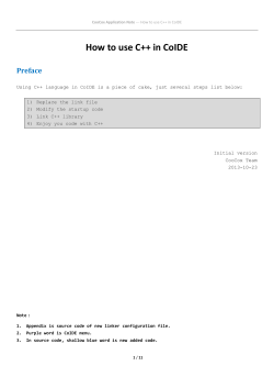
EDE has three main functions: Edit / Project management, Build and
Debug. The figure below shows how these main functionalities relate to
each other.
EDE
toolchain selection
editor
project management
tool options
EDIT
makefile
make
compiler
assembler
linker
BUILD
absolute file
debugger
Figure 2-1: EDE development flow
• • • • • • • •
DEBUG
TriCore User's Manual
2-4
In the Edit part you make all your changes:
-
create a project space
create and maintain one or more projects in a project space
add, create and edit source files in a project
set the options for each tool in the toolchain
select another toolchain if you want to create an application for
another target than the TriCore.
In the Build part you build your files:
- a makefile (created by the Edit part) is used to invoke the needed
toolchain components, resulting in an absolute object file.
In the Debug part you can debug your project:
- call the TASKING debugger CrossView Pro" with the generated
absolute object file.
This Getting Started Chapter guides you step-by-step through the most
important features of EDE
GETTING STARTED
The TASKING EDE is an embedded environment and differs from a native
program development.
A native program development environment is often used to develop
applications for systems where the host system and the target are the
same. Therefore, it is possible to run a compiled application directly from
the development environment.
In an embedded environment, however, a simulator or target hardware is
required to run an application. TASKING offers a number of simulators
and target hardware debuggers.
Toolchain overview
You can use all tools in the toolchain from the embedded development
environment (EDE) and from the command line in a Command Prompt
window or a UNIX shell.
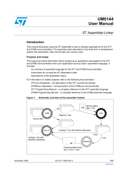
The next illustration shows all components of the TriCore toolchain with
their input and output files.
Getting Started
2-5
C++ source file
.cc
C++ compiler
cptc
C source file
.ic
C source file .c
(hand coded)
C compiler
ctc
error messages .err
assembly file
.src
assembly file .asm
(hand coded)
list file .lst
assembler
astc
error messages .ers
relocatable object file
.o
archiver
artc
relocatable object library.a
relocatable linker object file .out
linker script file
.lsl
relocatable linker object file .out
Intel Hex
absolute object file
.hex
ELF/DWARF 2
absolute object file
.elf
CrossView Pro
debugger
xfwtc
TriCore execution
environment
Figure 2-2: TriCore toolchain
• • • • • • • •
linker
ltc
linker map file .map
error messages .elk
memory definition
file .mdf
Motorola S-record
absolute object file
.sre
IEEE-695
absolute object file
.abs
TriCore User's Manual
2-6
The following table lists the file types used by the TriCore toolchain.
Extension
Description
Source files
.cc
C++ source file, input for the C++ compiler
.c
C source file, input for the C compiler
.asm
Assembler source file, hand coded
.lsl
Linker script file using the Linker Script Language
Generated source files
.ic
C source file, generated by the C++ compiler, input for the C
compiler
.src
Assembler source file, generated by the C compiler, does not
contain macros
GETTING STARTED
Object files
.o
ELF/DWARF relocatable object file, generated by the assembler
.a
Archive with ELF/DWARF object files
.abs
IEEE-695 absolute object file, generated by the locating part of
the linker
.out
Relocatable linker output file
.elf
ELF/DWARF absolute object file, generated by the locating part
of the linker
.hex
Absolute Intel Hex object file
.sre
Absolute Motorola S-record object file
List files
.lst
Assembler list file
.map
Linker map file
.mdf
Memory definition file
.mcr
MISRA-C report file
Error list files
.err
Compiler error messages file
.ers
Assembler error messages file
.elk
Linker error messages file
Table 2-1: File extensions
Getting Started
2.2 WORKING WITH PROJECTS IN EDE
EDE is a complete project environment in which you can create and
maintain project spaces and projects. EDE gives you direct access to the
tools and features you need to create an application from your project.
A project space holds a set of projects and must always contain at least one
project. Before you can create a project you have to setup a project space.
All information of a project space is saved in a project space file (.psp):
• a list of projects in the project space
• history information
Within a project space you can create projects. Projects are bound to a
target! You can create, add or edit files in the project which together form
your application. All information of a project is saved in a project file
(.pjt):
•
•
•
•
•
•
the target for which the project is created
a list of the source files in the project
the options for the compiler, assembler, linker and debugger
the default directories for the include files, libraries and executables
the build options
history information
When you build your project, EDE handles file dependencies and the
exact sequence of operations required to build your application. When
you push the Build button, EDE generates a makefile, including all
dependencies, and builds your application.
Overview of steps to create and build an application
1. Create a project space
2. Add one or more projects to the project space
3. Add files to the project
4. Edit the files
5. Set development tool options
6. Build the application
• • • • • • • •
2-7
TriCore User's Manual
2-8
2.3 START EDE
Start EDE
• Double-click on the EDE shortcut on your desktop.
- or Launch EDE via the program folder created by the installation program.
Select Start -> Programs -> TASKING toolchain -> EDE.
Figure 2-3: EDE icon
The EDE screen contains a menu bar, a toolbar with command buttons,
one or more windows (default, a window to edit source files, a project
window and an output window) and a status bar.
GETTING STARTED
Project Options Compile
Build Rebuild Debug On-line Manuals
Document Windows
Used to view and edit files.
Project Window
Contains several
tabs for viewing
information about
projects and other
files.
Figure 2-4: EDE desktop
Output Window
Contains several tabs to display
and manipulate results of EDE
operations. For example, to view
the results of builds or compiles.
Getting Started
2.4 USING THE SAMPLE PROJECTS
When you start EDE for the first time (see section 2.3, Start EDE), EDE
opens with a ready defined project space that contains several sample
projects. Each project has its own subdirectory in the examples directory.
Each directory contains a file readme.txt with information about the
example. The default project is called demo.pjt and contains a CrossView
Pro debugger example.
Select a sample project
To select a project from the list of projects in a project space:
1. In the Project Window, right-click on the project you want to open.
A menu appears.
2. Select Set as Current Project.
The selected project opens.
3. Read the file readme.txt for more information about the selected sample
project.
Building a sample project
To build the currently active sample project:
• Click on the Execute 'Make' command button.
Once the files have been processed you can inspect the generated messages
in the Build tab of the Output window.
2.5 CREATE A NEW PROJECT SPACE WITH A PROJECT
Creating a project space is in fact nothing more than creating a project
space file (.psp) in an existing or new directory.
Create a new project space
1. From the File menu, select New Project Space...
The Create a New Project Space dialog appears.
• • • • • • • •
2-9
2-10
TriCore User's Manual
2. In the the Filename field, enter a name for your project space (for
example MyProjects). Click the Browse button to select a directory first
and enter a filename.
GETTING STARTED
3. Check the directory and filename and click OK to create the .psp file in
the directory shown in the dialog.
A project space information file with the name MyProjects.psp is
created and the Project Properties dialog box appears with the project space
selected.
Getting Started
Add a new project to the project space
4. In the Project Properties dialog, click on the Add new project to project
space button (see previous figure).
The Add New Project to Project Space dialog appears.
• • • • • • • •
2-11
TriCore User's Manual
2-12
5. Give your project a name, for example getstart\getstart.pjt (a
directory name to hold your project files is optional) and click OK.
GETTING STARTED
A project file with the name getstart.pjt is created in the directory
getstart, which is also created. The Project Properties dialog box appears
with the project selected.
Add new files to the project
Now you can add all the files you want to be part of your project.
6. Click on the Add new file to project button.
The Add New File to Project dialog appears.
Getting Started
7. Enter a new filename (for example hello.c) and click OK.
A new empty file is created and added to the project. Repeat steps 6 and 7 if
you want to add more files.
8. Click OK.
The new project is now open. EDE loads the new file(s) in the editor in
separate document windows.
EDE automatically creates a makefile for the project (in this case
getstart.mak ). This file contains the rules to build your application.
EDE updates the makefile every time you modify your project.
Edit your files
9. As an example, type the following C source in the hello.c document
window:
#include <stdio.h>
void main(void)
{
printf("Hello World!\n");
}
10. Click on the Save the changed file <Ctrl-S> button.
EDE saves the file.
• • • • • • • •
2-13
TriCore User's Manual
2-14
2.6 SET OPTIONS FOR THE TOOLS IN THE TOOLCHAIN
The next step in the process of building your application is to select a
target processor and specify the options for the different parts of the
toolchain, such as the C and/or C++ compiler, assembler, linker and
debugger.
Select a target processor
1. From the Project menu, select Project Options...
The Project Options dialog appears.
GETTING STARTED
2. Expand the Processor entry and select Processor Definition.
3. In the Target processor list select (for example) TC11IB.
4. Click OK to accept the new project settings.
Set tool options
1. From the Project menu, select Project Options...
The Project Options dialog appears. Here you can specify options that are
valid for the entire project. To overrule the project options for the currently
active file instead, from the Project menu select Current File Options...
Getting Started
2. Expand the C Compiler entry.
The C Compiler entry contains several pages where you can specify C
compiler settings.
3. For each page make your changes. If you have made all changes click OK.
The Cancel button closes the dialog without saving your changes. With
the Defaults button you can restore the default project options (for the
current page, or all pages in the dialog).
4. Make your changes for all other entries (Assembler, Linker, CrossView Pro)
of the Project Options dialog in a similar way as described above for the C
compiler.
If available, the Options string field shows the command line options
that correspond to your graphical selections.
• • • • • • • •
2-15
TriCore User's Manual
2-16
2.7 BUILD YOUR APPLICATION
If you have set all options, you can actually compile the file(s). This results
in an absolute ELF/DWARF object file which is ready to be debugged.
Build your Application
To build the currently active project:
• Click on the Execute 'Make' command button.
The file is compiled, assembled, linked and located. The resulting file is
getstart.elf .
The build process only builds files that are out-of-date. So, if you click
Make again in this example nothing is done, because all files are
up-to-date.
GETTING STARTED
Viewing the Results of a Build
Once the files have been processed, you can see which commands have
been executed (and inspect generated messages) by the build process in
the Build tab of the Output window.
This window is normally open, but if it is closed you can open it by
selecting the Output menu item in the Window menu.
Compiling a Single File
1. Select the window (document) containing the file you want to compile or
assemble.
2. Click on the Execute 'Compile' command button. The following button
is the execute Compile button which is located in the toolbar.
If you selected the file hello.c, this results in the compiled and assembled
file hello.o.
Getting Started
Rebuild your Entire Application
If you want to compile, assemble and link/locate all files of your project
from scratch (regardless of their date/time stamp), you can perform a
rebuild.
• Click on the Execute 'Rebuild' command button. The following
button is the execute Rebuild button which is located in the toolbar.
2.8 HOW TO BUILD YOUR APPLICATION ON THE
COMMAND LINE
If you are not using EDE, you can build your entire application on the
command line. The easiest way is to use the control program cctc.
1. In a text editor, write the file hello.c with the following contents:
#include <stdio.h>
void main(void)
{
printf("Hello World!\n");
}
2. Build the file getstart.elf :
cctc -ogetstart.elf hello.c -v
The control program calls all tools in the toolchain. The -v option shows all
the individual steps. The resulting file is getstart.elf .
• • • • • • • •
2-17
TriCore User's Manual
2-18
2.9 DEBUG GETSTART.ELF
The application getstart.elf is the final result, ready for execution
and/or debugging. The debugger uses getstart.elf for debugging but
needs symbolic debug information for the debugging process. This
information must be included in getstart.elf and therefore you need
to compile and assemble hello.c once again.
cctc -g -ogetstart.elf hello.c
Now you can start the debugger with getstart.elf and see how it
executes.
Start CrossView Pro
• Click on the Debug application button.
CrossView Pro is launched. CrossView Pro will automatically download the
file getstart.elf for debugging.
GETTING STARTED
See the CrossView Pro Debugger User's Manual for more information.
CHAPTER
3
TRICORE
C LANGUAGE
TriCore User's Manual
CHAPTER
3-2
C LANGUAGE
3
TriCore C Language
3.1 INTRODUCTION
The TASKING C cross-compiler (ctc) fully supports the ISO C standard
and adds extra possibilities to program the special functions of the TriCore.
In addition to the standard C language, the compiler supports the
following:
• extra data types, like __fract, __laccum and __packb
• intrinsic (built-in) functions that result in TriCore specific assembly
instructions
• pragmas to control the compiler from within the C source
• predefined macros
• the possibility to use assembly instructions in the C source
• keywords to specify memory types for data and functions
• attributes to specify alignment and absolute addresses
All non-standard keywords have two leading underscores (__).
In this chapter the TriCore specific characteristics of the C language are
described, including the above mentioned extensions.
3.2 DATA TYPES
3.2.1
FUNDAMENTAL DATA TYPES
The TriCore architecture defines the following fundamental data types:
•
•
•
•
An 8-bit byte
A 16-bit short
A 32-bit word
A 64-bit double word
The next table shows the mapping between these fundamental data types
and the C language data types.
• • • • • • • •
3-3
TriCore User's Manual
3-4
Type
Keyword
Boolean
_Bool
Character
char
signed char
unsigned char
Integral
short
signed short
unsigned short
Size
(bit)
Align
(bit)
Ranges
8
8
0 or 1
8
8
-27 .. 27-1
8
8
0 .. 28-1
16
16
-215 .. 215-1
16
16
0 .. 216-1
32
16
-231 .. 231-1
32
16
0 .. 232-1
8
16
32
8
16
-27 .. 27-1
-215 .. 215-1
-231 .. 231-1
64
32
-263 .. -263-1
64
32
0 .. 264-1
32
32
0 .. 232-1
32
16
-3.402e38 .. -1.175e-38
1.175e-38 .. 3.402e38
64
32
-1.797e308 .. -2.225e-308
2.225e-308 .. 1.797e308
int
signed int
long
signed long
unsigned int
unsigned long
enum
long long
signed
long long
unsigned
long long
C LANGUAGE
Pointer
pointer to data
pointer to func
FloatingPoint
float
double
long double
Table 3-1: Data Types
When you use the enum type, the compiler will use the smallest sufficient
integer type, unless you use compiler option --integer-enumeration
(always use 32-bit integers for enumeration).
See also the TriCore Embedded Applications Binary Interface (EABI).
TriCore C Language
3.2.2
3-5
FRACTIONAL DATA TYPES
The TASKING TriCore C compiler ctc additionally supports the following
fractional types:
Type
Fract
Accum
Size
(bit)
Align
(bit)
Ranges
__sfract
16
16
[-1, 1>
__fract
32
32
[-1, 1>
__laccum
64
64
[-131072,131072>
Keyword
Table 3-2: Fractional Data Types
The __sfract type has 1 sign bit + 15 mantissa bits
The __fract type has 1 sign bit + 31 mantissa bits
The __laccum type has 1 sign bit + 17 integral bits + 46 mantissa bits.
The _accum type is only included for compatibility reasons and is mapped
to __laccum.
The TASKING C compiler ctc fully supports fractional data types which
allow you to use normal expressions:
__fract f, f1, f2;
/* Declaration of fractional variables
*/
f1 = 0.5;
f2 = 0.242;
/* Assignment of a fractional constants
*/
f = f1 * f2;
/* Multiplication of two fractionals
*/
The TriCore instruction set supports most basic operation on fractional
types directly. To obtain more portable code, you can use several intrinsic
functions that use fractional types. Fractional values are automatically
saturated.
Section 3.5, Intrinsic Functions explains intrinsic functions.
Section 1.5.2, Fractional Arithmetic Support in Chapter TriCore C Language
of the Reference Manual lists the intrinsic functions.
• • • • • • • •
TriCore User's Manual
3-6
Promotion rules
For the three fractional types, the promotion rules are similar to the
promotion rules for char, short, int, long and long long. This means
that for an operation on two different fractional types, the smaller type is
promoted to the larger type before the operation is performed.
When you mix a fractional type with a float or double type, the
fractional number is first promoted to float respectively double.
When you mix an integer type with the __laccum type, the integer is first
promoted to __laccum.
Because of the limited range of __sfract and __fract, only a few
operations make sense when combining an integer with an __sfract or
__fract. Therefore, the TriCore compiler only supports the following
operations for integers combined with fractional types:
left
oper
right
result
fractional
fractional
*
integer
integer
*
fractional fractional
fractional
/
integer
fractional
fractional
<<
integer
fractional
fractional
>>
integer
fractional
fractional: __sfract, __fract
integer: char, short, int, long, long long
C LANGUAGE
Table 3-3: Fractional operations for integers with fractional types
3.2.3
BIT DATA TYPE
The TASKING TriCore C compiler ctc additionally supports the bit data
type:
Type
Bit
Keyword
__bit
Table 3-4: Bit Data Type
Size
(bit)
Align
(bit)
Range
8
8
0 or 1
TriCore C Language
The TriCore instruction set supports some operations of the __bit type
directly.
The following rules apply to __bit type variables:
• A __bit type variable is always unsigned.
• A __bit type variable can be exchanged with all other type-variables.
The compiler generates the correct conversion.
A __bit type variable is like a boolean. Therefore, if you convert an
int type variable to a __bit type variable, it becomes 1 (true) if the
integer is not equal to 0, and 0 (false) if the integer is 0. The next two
C source lines have the same effect:
bit_variable = int_variable;
bit_variable = int_variable ? 1 : 0;
•
•
•
•
•
•
•
•
Pointer to __bit is not allowed when it has the __atbit() qualifier.
The __bit type is allowed as a structure member.
A __bit type variable is allowed as a parameter of a function.
A __bit type variable is allowed as a return type of a function.
A __bit typed expression is allowed as switch expression.
The sizeof of a __bit type is 1.
Global or static __bit type variable can be initialized.
A __bit type variable can be declared absolute using the __atbit
attribute. See section 3.3.2 Declare a Data Object at an Absolute
Address: __at() and __atbit() for more details.
• A __bit type variable can be declared volatile.
Promotion Rules
For the __bit type, the promotion rules are similar to the promotion rules
for char, short, int, long and long long.
• • • • • • • •
3-7
TriCore User's Manual
3-8
3.2.4
PACKED DATA TYPES
The TASKING TriCore C compiler ctc additionally supports the following
packed types:
Type
Packed
Keyword
__packb
signed __packb
unsigned __packb
__packhw
signed __packhw
unsigned __packhw
Size
(bit)
Align
(bit)
Ranges
32
16
4x: -27 .. 27-1
32
16
4x: 0 .. 28-1
32
16
2x: -215 .. 215-1
32
16
2x: 0 .. 216-1
Table 3-5: Fractional Data Types
A __packb value consists of four signed or unsigned char values.
A __packhw value consists of two signed or unsigned short values.
The TriCore instruction set supports a number of arithmetic operations on
packed data types directly. For example, the following function:
__packb add4 ( __packb a, __packb b )
{
return a + b;
}
C LANGUAGE
results into the following assembly code:
add4:
add.b
ret16
d2,d4,d5
Section 3.5, Intrinsic Functions explains intrinsic functions.
Section 1.5.3, Packed Data Type Support in Chapter TriCore C Language of
the Reference Manual lists the intrinsic functions.
Halfword Packed Unions and Structures
To minimize space consumed by alignment padding with unions and
structures, elements follow the minimum alignment requirements imposed
by the architecture. The TriCore arichitecture supports access to 32-bit
integer variables on halfword boundaries.
TriCore C Language
3-9
Because only doubles, circular buffers, __laccum or pointers require the
full word access, structures that do not contain members of these types are
automatically halfword (2-bytes) packed.
Structures and unions that are divisible by 64-bit or contain members that
are divisible by 64-bit, are word packed to allow efficient access through
LD.D and ST.D instructions. These load and store operations require word
aligned structures that are divisible by 64-bit. If necessary, 64-bit divisible
structure elements are aligned or padded to make the structure 64-bit
accessible.
With #pragma pack 2 you can disable the LD.D/ST.D structure and
union copy optimization to ensure halfword structure and union packing
when possible. This "limited" halfword packing only supports structures
and unions that do not contain double, circular buffer, __laccum or
pointer type members and that are not qualified with #pragma align to
get an alignment larger than 2-byte. With #pragma pack 0 you turn off
halfword packing again.
#pragma pack 2
typedef struct {
unsigned char
unsigned char
unsigned short
unsigned short
unsigned short
} packed_struct;
#pragma pack 0
uc1;
uc2;
us1;
us2;
us3;
When you place a #pragma pack 0 before a structure or union, its
alignment will not be changed:
#pragma pack 0
packed_struct pstruct;
The alignment of data sections and stack can also affect the alignment of
the base address of a halfword packed structure. A halfword packed
structure can be aligned on a halfword boundary or larger alignment.
When located on the stack or at the beginning of a section, the alignment
becomes a word, because of the minimum required alignment of data
sections and stack objects. A stack or data section can contain any type of
object. To avoid wrong word alignment of objects in the section, the
section base is also word aligned.
• • • • • • • •
TriCore User's Manual
3-10
3.3 MEMORY QUALIFIERS
You can use static memory qualifiers to allocate static objects in a
particular part of the addressing space of the processor.
In addition, you can place variables at absolute addresses with the
keyword __at(). If you declare an integer at an absolute address, you
can declare a single bit of that variable as bit variable with the keyword
__atbit().
3.3.1
DECLARE A DATA OBJECT IN A SPECIAL PART
OF MEMORY
C LANGUAGE
With a memory qualifier you can declare a variable in a specific part of the
addressing space. You can use the following memory qualifiers:
__near
The declared data object will be located in the first 16 kB of
a 256 MB block. These parts of memory are directly
addressable with the absolute addressing mode (see section
4.4.1, Operands and Addressing Modes, in Chapter TriCore
Assembly Language).
__far
The data object can be located anywhere in the indirect
addressable memory region.
If you do not specify __near or __far, the compiler chooses where to
place the declared object. With the compiler option -N (maximum size in
bytes for data elements that are default located in __near sections) you
can specify the size of data objects which the compiler then by default
places in near memory.
__a0
The data object is located in a section that is addressable with
a sign-extended 16-bit offset from address register A0.
__a1
The data object is located in a section that is addressable with
a sign-extended 16-bit offset from address register A1.
__a8
The data object is located in a section that is addressable with
a sign-extended 16-bit offset from address register A8.
__a9
The data object is located in a section that is addressable with
a sign-extended 16-bit offset from address register A9.
TriCore C Language
Address registers A0, A1, A8, and A9 are designated as system global
registers. They are not part of either context partition and are not
saved/restored across calls. They can be protected against write access by
user applications.
By convention, A0 and A1 are reserved for compiler use, while A8 and A9
are reserved for OS or application use. A0 is used as a base pointer to the
small data section, where global data elements can be accessed using
base + offset addressing. A0 is initialized by the execution environment.
A1 is used as a base pointer to the literal data section. The literal data
section is a read-only data section intended for holding address constants
and program literal values. Like A0, it is initialized by the execution
environment.
As noted, A8 and A9 are reserved for OS use, or for application use in
cases where the application and OS are tightly coupled.
All these memory qualifiers (__near, __far, __a0, __a1, __a8 and
__a9) are related to the object being defined, they influence where the
object will be located in memory. They are not part of the type of the
object defined. Therefore, you cannot use these qualifiers in typedefs, type
casts or for members of a struct or union.
Examples:
To declare a fast accessible integer in directly addressable memory:
int __near Var_in_near;
To allocate a pointer in far memory (the compiler will not use absolute
addressing mode):
__far int *Ptr_in_far;
To declare and initialize a string in A0 memory:
char __a0 string[] = "TriCore";
If you use the __near memory qualifier, the compiler generates faster
access code for those (frequently used) variables. Pointers are always
32-bit.
Functions are by default allocated in ROM. In this case you can omit the a
memory qualifier. You cannot use memory qualifiers for function return
values.
• • • • • • • •
3-11
TriCore User's Manual
3-12
Some examples of using memory qualifiers:
int __near *p;
int __far *g;
g = p;
/* pointer to int in __near memory
(pointer has 32-bit size)
*/
/* pointer to int in __far memory
(pointer has 32-bit size)
*/
/* the compiler issues a warning
*/
You cannot use memory qualifiers in structure declarations:
struct S {
__near int i;
__far int *p;
}
/* put an integer in near
memory: Incorrect !
*/
/* put an integer pointer in
far memory: Incorrect !
*/
If a library function declares a variable in near memory and you try to
redeclare the variable in far memory, the linker issues an error:
extern int _near foo;
/* extern int in near memory*/
int __far foo;
/* int in far memory
*/
The usage of the variables is always without a storage specifier:
char __near example;
example = 2;
C LANGUAGE
The generated assembly would be:
mov16 d15,2
st.b example,d15
All allocations with the same storage specifiers are collected in units called
'sections'. The section with the __near attribute will be located within the
first 16 kB of of each 256 MB block.
With the linker it is possible to control the location of sections manually.
See Chapter 7 Linker.
TriCore C Language
3.3.2
DECLARE A DATA OBJECT AT AN ABSOLUTE
ADDRESS: __at() AND __atbit()
Just like you can declare a variable in a specific part of memory, you can
also place an object at an absolute address in memory. This may be useful
to interface with other programs using fixed memory schemes, or to access
special function registers.
With the attribute __at() you can specify an absolute address.
Examples
int myvar __at(0x100);
The variable myvar is placed at address 0x100.
unsigned char Display[80*24] __at( 0x2000 )
The array Display is placed at address 0x2000. In the generated
assembly, an absolute section is created. On this position space is reserved
for the variable Display.
Restrictions
Take note of the following restrictions if you place a variable at an
absolute address:
• You can place only global variables at absolute addresses. Parameters
of functions, or automatic variables within functions cannot be placed
at absolute addresses.
• When declared extern, the variable is not allocated by the compiler.
When the same variable is allocated within another module but on a
different address, the compiler, assembler or linker will not notice,
because an assembler external object cannot specify an absolute
address.
• When the variable is declared static, no public symbol will be
generated (normal C behavior).
• You cannot place functions at absolute addresses.
• Absolute variables cannot overlap each other. If you declare two
absolute variables at the same address, the assembler and / or linker
issues an error. The compiler does not check this.
• When you declare the same absolute variable within two modules, this
produces conflicts during link time (except when one of the modules
declares the variable 'extern').
• • • • • • • •
3-13
TriCore User's Manual
3-14
Declaring a bit variable with __atbit()
If you have defined a 32-bits base variable (int, long) you can declare a
single bit of that variable as a bit variable with the keyword __atbit().
The syntax is:
__atbit( name, offset )
name is the name of an integer variable in which the bit is located. offset
(range 0-31) is the bit-offset within the variable.
If you have defined an absolute integer variable with the keyword
__at(), you can declare a single bit of that variable as an absolute bit
variable with __atbit().
Example
int
__bit
bw
myb
__at(0x100);
__atbit( bw, 3 );
Note that the keyword __bit is used to declare the variable myb as a bit,
and that the keyword __atbit() is used to declare that variable at an
absolute offset in variable bw.
See also section 3.2.3, Bit Data Type.
C LANGUAGE
Restrictions
• You can only use the __atbit() qualifier on variables of type __bit.
• When a variable is __atbit() qualified it represents an alias of a bit
in another variable. Therefore, it cannot be initialized.
• You can only use the __atbit() qualifier on variables which have
either a global scope or file scope.
TriCore C Language
3.4 DATA TYPE QUALIFIERS
3.4.1
CIRCULAR BUFFERS: __circ
The TriCore core has support for implementing specific DSP tasks, such as
finite impulse response (FIR) and infinite impulse response (IIR) filters and
fast Fourier transforms (FFTs). For the FIR and IIR filters the TriCore
architecture supports the circular addressing mode and for the FFT the
bit-reverse addressing mode. The TriCore C compiler supports circular
buffers for these DSP tasks. This way, the TriCore C compiler makes
hardware features available at C source level instead of at assembly level
only.
A circular buffer is a linear (one dimensional) array that you can access by
moving a pointer through the data. The pointer can jump from the last
location in the array to the first, or vice-versa (the pointer wraps-around).
This way the buffer appears to be continuous. The TriCore C compiler
supports the __circ keyword (circular addressing mode) for this type of
buffer.
Example: __circ
__fract __circ circbuffer[10];
__fract __circ *ptr_to_circbuffer = circbuffer;
Here, circbuffer is declared as a circular buffer. The compiler aligns the
base address of the buffer on the access width (in this example an int, so
4 bytes). The compiler keeps the buffer size and uses it to control pointer
arithmetic of pointers that are assigned to the buffer later.
You can perform operations on circular pointers with the usual C pointer
arithmetic with the difference that the pointer will wrap. When you acces
the circular buffer with a circular pointer, it wraps at the buffer limits.
Circular pointer variables are 64 bits in size.
Example:
while( *Pptr_to_circbuf++ );
Indexing in the circular buffer, using an integer index, is treated equally to
indexing in a non-circular array.
Example:
int i = circbuf[3];
• • • • • • • •
3-15
TriCore User's Manual
3-16
The index is not calculated modulo; indexing outside the array boundaries
yields undefined results.
If you want to initialize a circular pointer with a dynamically allocated
buffer at run-time, you should use the intrinsic function __initcirc() :
#define N 100
unsigned short s = sizeof(__fract);
__fract *ptr_to_circbuf = calloc( N, s );
circbuf = __initcirc( ptr_to_circbuf, N * s, 0 * s );
3.4.2
DECLARE AN SFR BIT FIELD: __sfrbit16 AND
__sfrbit32
With the data type qualifiers __sfrbit16 and __sfrbit32 you can
declare bit fields in special function registers.
According to the TriCore Embedded Applications Binary Interface, 'normal'
bit fields are accessed as char, short or int. Thus:
• fields with a width of 8-bits or less impose only byte alignments
• fields with a width from 9 to 16 bits impose halfword alignment
• fields with a width from 17 to 32 bits impose word alignment
C LANGUAGE
If you declare bit fields in special function registers, this behavior is not
always desired: some special function registers require 16-bit or 32-bit
access. To force 16-bit or 32-bit access, you can use the data type
qualifiers __sfrbit16 and __sfrbit32.
For each supported target, a special function register file
(regcpu_name.sfr) is delivered with the TriCore toolchain. In normal
circumstances you should not need to declare SFR bit fields.
Example
The next example is part of an SFR file and illustrates the declaration of a
special function register using the data type qualifier __sfrbit32:
TriCore C Language
3-17
typedef volatile union
{
struct
{
unsigned __sfrbit32 SRPN : 1;
unsigned int : 2;
unsigned __sfrbit32 TOS
: 2;
unsigned __sfrbit32 SRE
: 1;
unsigned __sfrbit32 SRR
: 1;
unsigned __sfrbit32 CLRR : 1;
unsigned __sfrbit32 SETR : 1;
unsigned int : 16;
} B;
/* BCU Service Priority
Number
*/
/* BCU Type-of-Service
Control
*/
/* BCU Service Request
Enable Control
*/
/* BCU SerService Request
Flag
*/
/* BCU Request Clear Bit */
/* BCU Request Set Bit
*/
int I;
} BCU_SRC_type;
#define BCU_SRC (*(BCU_SRC_type*)(0xF00002FC))
/* BCU Service Request Node
*/
You can now access the register and bit fields as follows:
#include <regtc10gp.sfr>
BCU_SRC.I |= 0xb32a;
/* access BCU Service Request
Control register as a whole
BCU_SRC.B.SRE = 0x1;
/* access SRE bit field of BCU
Service Request Control register */
*/
Restrictions
You can use the __sfrbit32 and __sfrbit16 data type qualifiers only
for int types. The compiler issues an error if you use for example
__sfrbit32 char x : 8;
When you use the __sfrbit32 and __sfrbit16 data type qualifiers for
other types than a bit field, the compiler ignores this without a warning.
For example, __sfrbit32 int global; is equal to int global;.
Structures or unions that contain a member qualified with __sfrbit16,
are zero padded to complete a halfword if necessary. The structure or
union will be halfword aligned.
Structures or unions that contain a member qualified with __sfrbit32,
are zero padded to complete a full word if necessary. The structure or
union will be word aligned.
• • • • • • • •
TriCore User's Manual
3-18
3.5 INTRINSIC FUNCTIONS
Some specific TriCore assembly instructions have no equivalence in C.
Intrinsic functions give the possibility to use these instructions. Intrinsic
functions are predefined functions that are recognized by the compiler.
The compiler then generates the most efficient assembly code for these
functions.
The compiler always inlines the corresponding assembly instructions in the
assembly source rather than calling the function. This avoids unnecessary
parameter passing and register saving instructions which are normally
necessary when a function is called.
Intrinsic functions produce very efficient assembly code. Though it is
possible to inline assembly code by hand, registers are used even more
efficient by intrinsic functions. At the same time your C source remains
very readable.
You can use intrinsic functions in C as if they were ordinary C (library)
functions. All intrinsics begin with a double underscore character. The
following example illustrates the use of an intrinsic function and its
resulting assembly code.
x = __min( 4,5 );
The resulting assembly code is inlined rather than being called:
mov16
min
d2,#4
d2,d2,#5
C LANGUAGE
The intrinsics cover the following subjects:
•
•
•
•
•
•
•
•
Minimum and maximum of (short) integers
Fractional data type support
Packed data type support
Interrupt handling
Insert single assembly instruction
Register handling
Insert / extract bitfields and bits
Miscellaneous
For extended information about all available intrinsic functions, refer to
section 1.5, Intrinsic Functions, in Chapter TriCore C Language of the
Reference Manual.
TriCore C Language
3-19
3.6 USING ASSEMBLY IN THE C SOURCE: __asm()
With the __asm() keyword you can use assembly instructions in the C
source and pass C variables as operands to the assembly code. Be aware
that C modules that contain assembly are not portable and harder to
compile in other environments.
The compiler does not interpret assembly blocks but passes the assembly
code to the assembly source file. Possible errors can only be detected by
the assembler.
General syntax of the __asm keyword
__asm( "instruction_template"
[ : output_param_list
[ : input_param_list
[ : register_save_list]]] );
instruction_template
Assembly instructions that may contain
parameters from the input list or output list in
the form: %parm_nr
%parm_nr[.regnum] Parameter number in the range 0 .. 9. With the
optional .regnum you can access an individual
register from a register pair or register quad. For
example, with register pair d0/d1, .0 selects
register d0.
output_param_list
[[ "=[&]constraint_char"(C_expression)],...]
input_param_list
[[ "constraint_char"(C_expression)],...]
&
Says that an output operand is written to before
the inputs are read, so this output must not be
the same register as any input.
constraint _char
Constraint character: the type of register to be
used for the C_expression.
(see table 3-6)
C_expression
Any C expression. For output parameters it must
be an lvalue, that is, something that is legal to
have on the left side of an assignment.
register_save_list
register_name
• • • • • • • •
[["register_name"],...]
Name of the register you want to reserve.
TriCore User's Manual
3-20
Typical example: multiplying two C variables using assembly
int a,b,result;
void main( void )
{
__asm("mul\t%0,%1,%2" : "=d"(result) : "d"(a), "d"(b) );
}
generated code:
ld.w
ld.w
mul
st.w
d15,a
d0,b
d15,d15,d0
result,d15
%0 corresponds to the first C variable, %1 corresponds to the second and
so on. The escape sequence \t generates a tab.
Specifying registers for C variables
With a constraint character you specify the register type for a parameter.
In the example above, the d is used to force the use of data registers for
the parameters a, b and result.
C LANGUAGE
You can reserve the registers that are used in the assembly instructions,
either in the parameter lists or in the reserved register list
(register_save_list). The compiler takes account of these lists, so no
unnecessary register saves and restores are placed around the inline
assembly instructions.
Constraint
character
Type
Operand
Remark
a
Address register
a0 .. a15
d
Data register
d0 .. d15
e
Data register pair
e0,e2,..,e14
e0 = pair d0/d1, e2 = d2/d3, ...
m
Memory
variable
Stack or memory operand
number
Type of operand it
is associated with
same as
%number
Indicates that %number and
number are the same register.
Table 3-6: Available input/output operand constraints
TriCore C Language
Loops and conditional jumps
The compiler does not detect loops with multiple __asm statements or
(conditional) jumps across __asm statements and will generate incorrect
code for the registers involved.
If you want to create a loop with __asm, the whole loop must be
contained in a single __asm statement. The same counts for (conditional)
jumps. As a rule of thumb, all references to a label in an __asm statement
must be in that same statement.
Example 1: no input or output
A simple example without input or output parameters. You can just output
any assembly instruction:
__asm( "nop" );
Generated code:
nop
Example 2: using output parameters
Assign the result of inline assembly to a variable. With the constraint d a
data register is chosen for the parameter; the compiler decides which data
register it uses. The %0 in the instruction template is replaced with the
name of this data register. Finally, the compiler generates code to assign
the result to the output variable.
int result;
void main( void )
{
__asm( "mov %0,#0xFF" : "=d"(result));
}
Generated assembly code:
mov
st.w
• • • • • • • •
d15,#0xFF
result,d15
3-21
TriCore User's Manual
3-22
Example 3: using input and output parameters
Multiply two C variables and assign the result to a third C variable. Data
type registers are necessary for the input and output parameters (constraint
d, %0 for result, %1 for a and %2 for b in the instruction template). The
compiler generates code to move the input expressions into the input
registers and to assign the result to the output variable.
int a, b, result;
void multiply( void )
{
__asm( "mul %0, %1, %2": "=d"(result): "d"(a), "d"(b) );
}
void main(void)
{
multiply();
}
Generated assembly code:
multiply:
ld.w
ld.w
mul
st.w
d15,a
d0,b
d15, d15, d0
result,d15
main:
j
multiply
C LANGUAGE
Example 4: reserve registers
If you use registers in the __asm statement, reserve them. Same as
Example 3, but now register d0 is a reserved register. You can do this by
adding a reserved register list (: "d0") (sometimes referred to as 'clobber
list'). As you can see in the generated assembly code, register d0 is not
used (the first register used is d1).
int a, b, result;
void multiply( void )
{
__asm( "mul %0, %1, %2": "=d"(result): "d"(a), "d"(b) : "d0" );
}
Generated assembly code:
ld.w
ld.w
mul
st.w
d15,a
d1,b
d15, d15, d1
result,d15
TriCore C Language
3-23
Example 5: input and output are the same
If the input and output must be the same you must use a number
constraint. The following example inverts the value of the input variable
ivar and returns this value to ovar. Since the assembly instruction not
uses only one register, the return value has to go in the same place as the
input value. To indicate that ivar uses the same register as ovar, the
constraint '0' is used which indicates that ivar also corresponds with %0.
int ovar;
void invert(int ivar)
{
__asm ("not %0": "=d"(ovar): "0"(ivar) );
}
void main(void)
{
invert(255);
}
Generated assembly code:
invert:
not
st.w
d4
ovar,d4
main:
mov
j
d4,#255
invert
Example 6: writing your own intrinsic function
Because you can use any assembly instruction with the __asm keyword,
you can use the __asm keyword to create your own intrinsic functions.
The essence of an intrinsic function is that it is inlined.
First write a function with assembly in the body using the keyword __asm.
We use the multiply routine from Example 3.
Next make sure that the function is inlined rather than being called. You
can do this with the function qualifier inline. This qualifier is discussed
in more detail in section 3.9.1, Inlining Functions.
• • • • • • • •
TriCore User's Manual
3-24
int a, b, result;
inline void __my_mul( void )
{
__asm( "mul %0, %1, %2": "=d"(result): "d"(a), "d"(b) );
}
void main(void)
{
// call to function __my_mul
__my_mul();
}
Generated assembly code:
main:
; __my_mul code is inlined here
ld.w d15,a
ld.w d0,b
mul
d15, d15, d0
st.w result,d15
As you can see, the generated assembly code for the function __my_mul is
inlined rather than called.
Example 7: accessing individual registers in a register pair
You can access the individual registers in a register pair by adding a '.'
after the operand specifier in the assembly part, followed by the index in
the register pair.
C LANGUAGE
int f1, f2;
void foo(double d)
{
__asm ("ld.w %0, %2.0\n"
"\tld.w %1, %2.1":"=&d"(f1),"=d"(f2):"e"(d) );
}
The first ld.w instruction uses index #0 of argument 2 (which is a double
placed in a DxDx register) and the second ld.w instruction uses index #1.
The input operand is located in register pair d4/d5. The assembly output
becomes:
ld.w
ld.w
st.w
st.w
ret16
d15, d4
d0, e4,1 ; note that e4,1 corresponds to d5
f1,d15
f2,d0
TriCore C Language
3-25
If the index is not a valid index (for example, the register is not a register
pair, or the argument has not a register constraint), the '.' is passed into the
assembly output. This way you can still use the '.' in assembly instructions.
3.7 CONTROLLING THE COMPILER: PRAGMAS
Pragmas are keywords in the C source that control the behavior of the
compiler. Pragmas sometimes overrule compiler options. In general
pragmas give directions to the code generator of the compiler.
The syntax is:
#pragma pragma-spec [ON | OFF | RESTORE | DEFAULT]
or:
_Pragma("pragma-spec [ON | OFF | RESTORE | DEFAULT]")
For example, you can set a compiler option to specify which optimizations
the compiler should perform. With the #pragma optimize flags you
can set an optimization level for a specific part of the C source. This
overrules the general optimization level that is set in the compiler options
dialog (command line option -O).
Some pragmas have an equivalent command line option. This is useful if
you want to overrule certain keywords in the C source without the need to
change the C source itself.
See section 5.1, Compiler Options, in Chapter 5, Tool Options, of the
Reference Manual.
The compiler recognizes the following pragmas, other pragmas are
ignored.
• • • • • • • •
Pragma name
Description
alias symbol=defined-symbol
Defines an alias for a symbol
align {n|restore}
Specifies object alignment.
See compiler option --align in
section 5.1, Compiler Options in
Chapter Tool Options of the
Reference Manual.
TriCore User's Manual
C LANGUAGE
3-26
Pragma name
Description
clear
noclear
Specifies 'clearing' of
non-initialized static/public
variables
CPU_functional_problem
DMU_functional_problem
Use software workarounds for the
specified functional problem.
See compiler option
--silicon-bug in section 5.1,
Compiler Options in Chapter Tool
Options of the Reference Manual.
default_a0_size value
Threshold for '__a0' allocation
default_a1_size value
Threshold for '__a1' allocation
default_near_size value
Threshold for '__near' allocation
extension isuffix
Enables the language extension to
specify imaginary floating-point
constants by adding an 'i' to the
constant
extern symbol
Forces an external reference
for_constant_data_use_memory
for_extern_data_use_memory
for_initialized_data_use_memory
for_uninitialized_data_use_memory
Specify a memory for the type of
data mentioned in the pragma. You
can specify near, far, a0, a8, a9 (or
a1 only for constant data)
indirect
Generates code for indirect
function calling. See compiler
option --indirect in section 5.1,
Compiler Options in Chapter Tool
Options of the Reference Manual.
indirect-runtime
Generates code for indirect
function calling to all runtime
functions. See compiler option
--indirect-runtime in section 5.1,
Compiler Options in Chapter Tool
Options of the Reference Manual.
inline
noinline
smartinline
Specifies function inlining.
See section 3.9.1, Inlining
Functions.
macro
nomacro
Turns macro expansion on
(default) or off.
message "string" ...
Emits a message to standard
output
TriCore C Language
3-27
Pragma name
Description
object_comment "string"
Generates a .comment section
with string in the .src file which
then appears in the object file.
optimize flags
endoptimize
Controls compiler optimizations.
See section 5.3, Compiler
Optimizations in Chapter Using the
Compiler
pack {2|0}
Specifies packing of structures.
See section 3.2.4, Packed Data
Types.
section
section
section
section
At startup copies corresponding
sections to RAM for initialization
code_init
const_init
vector_init
data_overlay
section type[=]"name"
section all
Changes section names.
See section 3.10, Compiler
Generated Sections and compiler
option -R in section 5.1, Compiler
Options in Chapter Tool Options of
the Reference Manual
source
nosource
Specifies which C source lines
must be shown in assembly
output.
See compiler option -s in section
5.1, Compiler Options in Chapter
Tool Options of the Reference
Manual.
switch {auto|jumptab|
linear|lookup|restore}
Specifies switch statement.
See section 3.11, Switch
Statement
tradeoff level
Specify tradeoff between speed (0)
and size (4). See compiler option
-t in section 5.1, Compiler Options
in Chapter Tool Options of the
Reference Manual.
warning [number,...]
Disables warning messages. See
compiler option -w in section 5.1,
Compiler Options in Chapter Tool
Options of the Reference Manual.
weak symbol
Marks a symbol as 'weak'
Table 3-7: Pragmas
• • • • • • • •
Allow overlaying data sections
TriCore User's Manual
3-28
3.8 PREDEFINED MACROS
C LANGUAGE
In addition to the predefined macros required by the ISO C standard, the
TASKING TriCore C compiler supports the predefined macros as defined in
Table 3-8. The macros are useful to create conditional C code.
Macro
Description
__DOUBLE_FP__
Defined when you do not use compiler option -F
(Treat double as float)
__SINGLE_FP__
Defined when you use compiler option -F (Treat
double as float)
__FPU__
Defined when you use compiler option
--fpu-present (Use hardware floating-point
instructions)
__CTC__
Identifies the compiler. You can use this symbol to flag
parts of the source which must be recognized by the
ctc compiler only. It expands to the version number of
the compiler.
__TASKING__
Identifies the compiler as the TASKING TriCore
compiler. It expands to 1.
__DSPC__
Indicates conformation to the DSP-C standard. It
expands to 1.
__DSPC_VERSION__
Expands to the decimal constant 200001L.
__VERSION__
Identifies the version number of the compiler. For
example, if you use version 2.1r1 of the compiler,
__VERSION__ expands to 2001 (dot and revision
number are omitted, minor version number in 3 digits).
__REVISION__
Identifies the revision number of the compiler. For
example, if you use version 2.1r1 of the compiler,
__REVISION__ expands to 1.
__BUILD__
Identifies the build number of the compiler, composed
of decimal digits for the build number, three digits for
the major branch number and three digits for the
minor branch number. For example, if you use build
1.22.1 of the compiler, __BUILD__ expands to
1022001. If there is no branch number, the branch
digits expand to zero. For example, build 127 results
in 127000000.
Table 3-8: Predefined macros
TriCore C Language
3.9 FUNCTIONS
3.9.1
INLINING FUNCTIONS: INLINE
You can use the inline keyword to tell the compiler to inline the
function body instead of calling the function. Use the __noinline
keyword to tell the compiler not to inline the function body.
You must define inline functions in the same source module as in which
you call the function, because the compiler only inlines a function in the
module that contains the function definition. When you need to call the
inline function from several source modules, you must include the
definition of the inline function in each module (for example using a
header file).
The compiler inserts the function body at the place the function is called.
If the function is not called at all, the compiler does not generate code for
it.
Example: inline
int
w,x,y,z;
inline int add( int a, int b )
{
int i = 4;
return( a + b );
}
void main( void )
{
w = add( 1, 2 );
z = add( x, y );
}
The function add() is defined before it is called. The compiler inserts
(optimized) code for both calls to the add() function. The generated
assembly is:
• • • • • • • •
3-29
TriCore User's Manual
3-30
main:
mov16
st.w
d15,#3
w,d15
ld.w
ld.w
add16
st.w
d15,x
d0,y
d0,d15
z,d0
Example: #pragma inline / #pragma noinline
Instead of the inline qualifier, you can also use #pragma inline and
#pragma noinline to inline a function body:
int
w,x,y,z;
#pragma inline
int add( int a, int b )
{
int i=4;
return( a + b );
}
#pragma noinline
C LANGUAGE
void main( void )
{
w = add( 1, 2 );
z = add( x, y );
}
If a function has an inline/__noinline function qualifier, then this
qualifier will overrule the current pragma setting.
#pragma smartinline
By default, small fuctions that are not too often called, are inlined. This
reduces execution time at the cost of code size (compiler option -Oi).
With the #pragma noinline / #pragma smartinline you can
temporarily disable this optimization.
With the compiler options --inline-max-incr and --inline-max-size
you have more control over the function inlining process of the compiler.
See for more information of these options, section Compiler Options in
Chapter Tool Options of the TriCore Reference Manual.
TriCore C Language
Combining inline with __asm to create intrinsic functions
With the keyword __asm it is possible to use assembly instructions in the
body of an inline function. Because the compiler inserts the (assembly)
body at the place the function is called, you can create your own intrinsic
function.
See section 3.6, Using Assembly in the C Source, for more information
about the __asm keyword.
Example 6 in that section shows how in combination with the inline
keyword an intrinsic function is created.
3.9.2
INTERRUPT AND TRAP FUNCTIONS
The TriCore C compiler supports a number of function qualifiers and
keywords to program interrupt service routines (ISR) or trap handlers. Trap
handlers may also be defined by the operating system if your target system
uses one.
An interrupt service routine (or: interrupt function, or: interrupt handler) is
called when an interrupt event (or: service request) occurs. This is always
an external event; peripherals or external inputs can generate an interrupt
signals to the CPU to request for service.
Unlike other interrupt systems, each interrupt has a unique interrupt
request priority number (IRPN). This number is (0 to 255) is set as the
pending interrupt priority number (PIPN) in the interrupt control register
(ICR) by the interrupt control unit. If multiple interrupts occur at the same
time, the priority number of the request with the hightest priority is set, so
this interrupt is handled.
The TriCore vector table provides an entry for each pending interrupt
priority number, not for a specific interrupt source. A request is handled if
the priority number is higher then the CPU priority number (CCPN). An
interrupt service routine can be interrupted again by another interrupt
request with a higher priority. Interrupts with priority number 0 are never
handled.
A trap service routine (or: trap function, or: trap handler) is called when a
trap event occurs. This is always an event generated within or by the
application. For example, a devide by zero or an invalid memory access.
• • • • • • • •
3-31
TriCore User's Manual
3-32
With the following function qualifiers you can declare an interrupt handler
or trap handler:
__interrupt()
__trap()
__interrupt_fast()
__trap_fast()
There is one special type of trap function which you can call manually, the
system call exception (trap class 6). See section 3.9.2.3, Defining a Trap
Service Routine Class 6.
__syscallfunc()
During the execution of an interrupt service routine or trap service routine,
the system blocks the CPU from taking further interrupt requests. With the
following keywords you can enable interrupts again, immediately after an
interrupt or trap function is called:
__enable_
__bisr_()
3.9.2.1 DEFINING AN INTERRUPT SERVICE ROUTINE
Interrupt functions cannot accept arguments and do not return anything:
C LANGUAGE
void __interrupt( vector ) isr( void )
{
...
}
The argument vector identifies the entry into the interrupt vector table
(0..255). Unlike other interrupt systems, the priority number (PIPN) of the
interrupt now being serviced by the CPU identifies the entry into the
vector table.
For an extensive description of the TriCore interrupt system, see the
TriCore 1 Unified Processor Core v1.3 Architecture Manual, Doc v1.3.3
[2002-09, Infineon]
The compiler generates an interrupt service frame for interrupts. The
difference between a normal function and an interrupt function is that an
interrupt function ends with an RFE instruction instead of a RET, and that
the lower context is saved and restored with a pair of SVLCX / RSLCX
instructions when one of the lower context registers is used in the
interrupt handler.
TriCore C Language
When you define an interrupt service routine with the __interrupt()
qualifier, the compiler generates an entry for the interrupt vector table.
This vector jumps to the interrupt handler.
When you define an interrupt service routine with the
__interrupt_fast() qualifier, the interrupt handler is directly placed in
the interrupt vector table, thereby eliminating the jump code. You should
only use this when the interrupt handler is very small, as there is only 32
bytes of space available in the vector table. The compiler does not check
this restriction.
Example
The next example illustrates the function definition for a function for a
software interrupt with vector number 0x30:
int c;
void __interrupt( 0x30 ) transmit( void )
{
c = 1;
}
3.9.2.2 DEFINING A TRAP SERVICE ROUTINE
The definition of a trap service routine is similar to the definition of an
interrupt service routine. Trap functions cannot accept arguments and do
not return anything:
void __trap( class ) tsr( void )
{
...
}
The argument class identifies the entry into the trap vector table. TriCore
defines eight classes of trap functions. Each class has its own trap handler.
When a trap service routine is called, the d15 register contains the
so-called Trap Identification Number (TIN). This number identifies the
cause of the trap. In the trap service routine you can test and branch on
the value in d15 to reach the sub-handler for a specific TIN.
The next table shows the classes supported by TriCore.
• • • • • • • •
3-33
TriCore User's Manual
3-34
Class
Description
Class 0
Reset
Class 1
Internal Protection Traps
Class 2
Instruction Errors
Class 3
Context Management
Class 4
System Bus and Peripheral Errors
Class 5
Assertion Traps
Class 6
System Call
Class 7
Non-Maskable Interrupt
For a complete overview of the trap system and the meaning of the trap
identification numbers, see the TriCore 1 Unified Processor Core v1.3
Architecture Manual, Doc v1.3.3 [2002-09, Infineon]
Analogous to interrupt service routines, the compiler generates a trap
service frame for interrupts.
When you define a trap service routine with the __trap() qualifier, the
compiler generates an entry for the interrupt vector table. This vector
jumps to the trap handler.
C LANGUAGE
When you define a trap service routine with the __trap_fast()
qualifier, the trap handler is directly placed in the trap vector table,
thereby eliminating the jump code. You should only use this when the
trap handler is very small, as there is only 32 bytes of space available in
the vector table. The compiler does not check this restriction.
3.9.2.3 DEFINING A TRAP SERVICE ROUTINE CLASS 6:
__syscallfunc()
A special kind of trap service routine is the system call trap. With a system
call the trap service routine of class 6 is called. For the system call trap, the
trap identification number (TIN) is taken from the immediate constant
specified with the function qualifier __syscallfunc() :
__syscallfunc(TIN)
TriCore C Language
3-35
The TIN is a value in the range 0 and 255. You can only use
__syscallfunc() in the function declaration. A function body is useless,
because when you call the function declared with __syscallfunc() , a
trap class 6 occurs which calls the corresponding trap service routine.
In case of the other traps, when a trap service routine is called, the system
places a trap identification number in d15.
Unlike the other traps, a class 6 trap service routine can contain arguments
and return a value. Arguments that are passed via the stack, remain on the
stack of the caller because it is not possible to pass arguments from the
user stack to the interrupt stack on a system call. This restriction, caused
by the TriCore's run-time behavior, cannot be checked by the compiler.
The next example illustrates the definition of a class 6 trap service routine
and the corresponding system call:
Example
__syscallfunc(1) int syscall_a( int, int );
__syscallfunc(2) int syscall_b( int, int );
int x;
void main( void )
{
x = syscall_a(1,2);
x = syscall_b(4,3);
}
// causes a trap class 6 with TIN = 1
// causes a trap class 6 with TIN = 2
int __trap( 6 ) trap6( int a, int b ) // trap class 6 handler
{
int tin;
__asm("mov %0,d15" : "=d"(tin)); // put d15 in C variable tin
}
• • • • • • • •
switch( tin )
{
case 1:
a += b;
break;
case 2:
a -= b;
break;
default:
break;
}
return a;
TriCore User's Manual
3-36
3.9.2.4 ENABLING INTERRUPT REQUESTS: __enable_,
__bisr_()
Enabling interrupt service requests
During the execution of an interrupt service routine or trap service routine,
the system blocks the CPU from taking further interrupt requests. You can
immediately re-enable the system to accept interrupt requests:
__interrupt(vector) __enable_ isr( void )
__trap(class) __enable_ tsr( void )
The compiler generates an enable instruction as first instruction in the
routine. The enable instruction sets the interrupt enable bit (ICR.IE) in the
interrupt control register.
You can also generate the enable instruction with the __enable()
intrinsic function, but it is not guaranteed that it will be the first instruction
in the routine.
Enabling interrupt service requests and setting CPU priority number
The function qualifier __bisr_() also re-enables the system to accept
interrupt requests. In addition, the current CPU priority number (CCPN) in
the interrupt control register is set:
C LANGUAGE
__interrupt(vector) __bisr_(CCPN) isr( void )
__trap(class) __bisr_(CCPN) tsr( void )
The argument CCPN is a number between 0 and 255. The system accepts
all interrupt requests that have a higher pending interrupt priority number
(PIPN) than the current CPU priority number. So, if the CPU priority
number is set to 0, the system accepts all interrupts. If it is set to 255, no
interrupts are accepted.
The compiler generates a bisr instruction as first instruction in the
routine. The bisr instruction sets the interrupt enable bit (ICR.IE) and the
current CPU priority number (ICR.CCPN) in the interrupt control register.
You can also generate the bisr instruction with the __bisr() intrinsic
function, but it is not guaranteed that it will be the first instruction in the
routine.
TriCore C Language
3-37
Setting the CPU priority number in a Class 6 trap service routine
The bisr instruction saves the lower context so passing and returning
arguments is not possible. Therefore, you cannot use the function qualifier
__bisr_() for class 6 traps.
Instead, you can use the function qualifier __enable_ to set the ICR.IE
bit, and the intrinsic function __mtcr( int, int ) to set the ICR.CCPN
value at the beginning of a class 6 trap service routine (or use the intrinsic
function __mtcr() to set both the ICR.IE bit and the ICR.CCPN value).
3.9.3
FUNCTION CALLING MODES: __indirect
Functions are default called with a single word direct call. However, when
you link the application and the target address appears to be out of reach
(+/- 16 MB from the callg or jg instruction), the linker generates an
error. In this case you can use the __indirect keyword to force the less
efficient, two and a half word indirect call to the function:
int __indirect foo( void )
{
...
}
With compiler option --indirect you tell the compiler to generate far calls
for all functions.
3.9.4 PARAMETER PASSING AND THE STACK MODEL:
__stackparm
The parameter registers D4..D7 and A4..A7 are used to pass the initial
function arguments. Up to 4 arithmetic types and 4 pointers can be passed
this way. A 64-bit argument is passed in an even/odd data register pair.
Parameter registers skipped because of alignment for a 64-bit argument
are used by subsequent 32-bit arguments. Any remaining function
arguments are passed on the stack. Stack arguments are pushed in
reversed order, so that the first one is at the lowest address. On function
entry, the first stack parameter is at the address (SP+0).
• • • • • • • •
void func1( int i, char *p, char c );
/* D4 A4 D5 */
void func2( int i1, double d, int i2 );
/* D4 E6 D5 */
void func3( char c1, char c2, char c3[] );
/* D4 D5 A4 */
TriCore User's Manual
3-38
void func4( double d1, int i1, double d2, int i2 );
/* E4 D6 stack D7 */
All function arguments passed on the stack are aligned on a multiple of 4
bytes. As a result, the stack offsets for all types except float are
compatible with the stack offsets used by a function declared without a
prototype.
Structures up to eight bytes are passed via a data register or data register
pair. Larger structures are passed via the stack.
Arithmetic function results of up to 32 bits are returned in the D2 register.
64-bit arithmetic types are returned in the register pair D2/D3 (E2).
Pointers are returned in A2, and circular pointers are returned in A2/A3.
When the function return type is a structure, it is copied to a "return area"
that is allocated by the caller. The address of this area is passed as an
implicit first argument in A4.
The following table summarize the registers used by the TriCore compiler
ctc:
Register
Usage
Register
Usage
D0
scratch
A0
global
scratch
A1
global
return register for
arithmetic types
A2
return register for
pointers
most significant part of
64 bit result
A3
scratch
parameter
A4
parameter
parameter
A5
parameter
parameter
A6
parameter
parameter
A7
parameter
saved register
A8
global
saved register
A9
global
saved register
A10
stack pointer
saved register
A11
link register
saved register
A12
saved register
saved register
A13
saved register
D1
E0
D2
C LANGUAGE
D3
D4
D5
D6
D7
D8
D9
D10
D11
D12
D13
E2
E4
E6
E8
E10
E12
TriCore C Language
3-39
Register
Usage
Register
Usage
D14
saved register
A14
saved register
saved register, implicit
register
A15
saved register, implicit
pointer
D15
E14
Table 3-9: Register usage
Stack Model: __stackparm
The function qualifier __stackparm changes the standard calling
convention of a function into a convention where all function arguments
are passed via the stack, conforming a so-called stack model. This
qualifier is only needed for situations where you need to use an indirect
call to a function for which you do not have a valid prototype.
The compiler sets the least significant bit of the function pointer when you
take the address of a function declared with the __stackparm qualifier,
so that these function pointers can be identified at run-time. The least
significant bit of a function pointer address is ignored by the hardware.
Example
void
plain_func ( int );
void __stackparm stack_func ( int );
void call_indirect ( unsigned int fp, int arg )
{
typedef __stackparm void (*SFP)( int );
typedef void (*RFP)( int );
SFP
RFP
}
• • • • • • • •
fp_stack;
fp_reg;
if ( fp & 1 )
{
fp_stack = (SFP) fp;
fp_stack( arg );
}
else
{
fp_reg = (RFP) fp;
fp_reg( arg );
}
3-40
TriCore User's Manual
C LANGUAGE
void main ( void )
{
call_indirect( (unsinged int) plain_func, 1 );
call_indirect( (unsinged int) stack_func, 2 );
}
TriCore C Language
3-41
3.10 COMPILER GENERATED SECTIONS
The compiler generates code and data in several types of sections. The
compiler uses the following section naming convention:
section_type_prefix.module_name.symbol_name
The prefix depends on the type of the section and determines if the
section is initialized, constant or uninitialized and which addressing mode
is used. The symbol_name is either the name of an object or the name of a
function.
Type
Name prefix
Description
code
.text
program code
neardata
.zdata
initialized __near data
fardata
.data
initialized __far data
nearrom
.zrodata
constant __near data
farrom
.rodata
constant __far data
nearbss
.zbss
uninitialized __near data (cleared)
farbss
.bss
uninitialized __far data (cleared)
nearnoclear
.zbss
uninitialized __near data
farnoclear
.bss
uninitialized __far data
a0data
.sdata
initialized __a0 data
a0rom
.srodata
constant __a0 data
a0bss
.sbss
uninitialized __a0 data (cleared)
a1rom
.ldata
constant __a1 data
a8data
.data_a8
initialized __a8 data
a8rom
.rodata_a8
constant __a8 data
a8bss
.bss_a8
uninitialized __a8 data (cleared)
a9data
.data_a9
initialized __a9 data
a9rom
.rodata_a9
constant __a9 data
a9bss
.bss_a9
uninitialized __a9 data (cleared)
Table 3-10: Section types and name prefixes
• • • • • • • •
TriCore User's Manual
3-42
Rename sections
You can change the default section names with one of the following
pragmas:
#pragma section type "string"
All sections of the specified type will be named "prefix.string". For
example,
#pragma section neardata "where"
all sections of type neardata have the name ".zdata.where ".
#pragma section type will restore the default section naming for
sections of this type.
#pragma section type restore will restore the previous setting
of #pragma section type.
#pragma section all "string"
All sections will be named "prefix.string", unless you use a type
specific renaming pragma. For example,
#pragma section all "here"
all sections have the syntax "prefix.here". For example, sections of
type neardata have the name ".zdata.here".
C LANGUAGE
#pragma section all will restore the default section naming (not
for sections that have a type specific renaming pragma).
#pragma section all restore will restore the previous setting of
#pragma section all.
Example:
#pragma section all "rename_1"
// .text.rename_1
// .data.rename_1
#pragma section code "rename_2"
// .text.rename_2
// .data.rename_1
See also compiler option -R in section Compiler Options in Chapter Tool
Options of the Reference Manual.
TriCore C Language
Influence section definition
The following pragmas also influence the section definition:
#pragma section code_init
Code sections are copied from ROM to RAM at program startup.
#pragma section const_init
Sections with constant data are copied from ROM to RAM at program
startup.
#pragma section vector_init
Sections with interrupts and trap vectors are copied from ROM to RAM
at program startup.
#pragma section data_overlay
The nearnoclear and farnoclear sections can be overlaid by other
sections with the same name. Since default section naming never leads
to sections with the same name, you must force the same name by
using one of the section renaming pragmas. To get noclear sections
instead of BSS sections you must also use #pragma noclear.
• • • • • • • •
3-43
TriCore User's Manual
3-44
3.11 SWITCH STATEMENT
ctc supports three ways of code generation for a switch statement: a jump
chain (linear switch), a jump table or a lookup table.
A jump chain is comparable with an if/else-if/else-if/else construction. A
jump table is a table filled with target addresses for each possible switch
value. The switch argument is used as an index within this table. A lookup
table is a table filled with a value to compare the switch argument with
and a target address to jump to. A binary search lookup is performed to
select the correct target address.
By default, the compiler will automatically choose the most efficient switch
implementation based on code and data size and execution speed. You
can influence the selection of the switch method with compiler option -t
(--tradeoff), which determines the speed/size tradeoff.
It is obvious that, especially for large switch statements, the jump table
approach executes faster than the lookup table approach. Also the jump
table has a predictable behavior in execution speed. No matter the switch
argument, every case is reached in the same execution time. However,
when the case labels are distributed far apart, the jump table becomes
sparse, wasting code memory. The compiler will not use the jump table
method when the waste becomes excessive.
With a small number of cases, the jump chain method can be faster in
execution and shorter in size.
How to overrule the default switch method
C LANGUAGE
You can overrule the compiler chosen switch method with a pragma:
#pragma
#pragma
#pragma
#pragma
switch
switch
switch
switch
linear
jumptab
lookup
auto
#pragma switch restore
/*
/*
/*
/*
force jump chain code */
force jump table code */
force lookup table code */
let the compiler decide
the switch method used */
/* restore previous switch
method */
Pragma switch auto is also the default of the compiler.
On the command line you can use compiler option --switch.
TriCore C Language
3-45
3.12 LIBRARIES
The compiler ctc comes with standard C libraries (ISO/IEC 9899:1999) and
header files with the appropriate prototypes for the library functions. The
standard C libraries are available in object format and in C or assembly
source code.
A number of standard operations within C are too complex to generate
inline code for. These operations are implemented as run-time library
functions.
The lib directory contains subdirectories with separate libraries for the
TriCore 1 and the TriCore 2. Furthermore, protected libraries are available
for several functional problems.
The protected library sets provide software bypasses for all supported CPU
functional problems. They must be used in conjunction with the
appropriate C compiler workarounds for CPU functional problems. For
more details refer to Chapter 9, CPU Functional Problems in the Reference
Manual.
The directory structure is:
\ctc\lib\
• • • • • • • •
tc1\
tc2\
p\
TriCore 1 libraries
TriCore 2 libraries
tc1130
tc11ib
tc1765
tc1766
tc1775
tc1796
tc1910
tc1912
tc1920
Protected
Protected
Protected
Protected
Protected
Protected
Protected
Protected
Protected
libraries
libraries
libraries
libraries
libraries
libraries
libraries
libraries
libraries
for
for
for
for
for
for
for
for
for
TC1130 problems
TC11IB problems
TC1765 problems
TC1766 problems
TC1775 problems
TC1796 problems
TC1910 problems
TC1912 problems
TC1920 problems
TriCore User's Manual
3-46
3.12.1 OVERVIEW OF LIBRARIES
Table 3-11 lists the libraries included in the TriCore (ctc) toolchain.
Library to link
Description
libc.a
C library
(Some functions require the floating-point library. Also
includes the startup code.)
libcs.a
C library single precision (compiler option -F)
(Some functions require the floating-point library. Also
includes the startup code.)
libcs_fpu.a
C library single precision with FPU instructions (compiler
option -F and --fpu-present)
libfp.a
Floating-point library (non-trapping)
libfpt.a
Floating-point library (trapping)
(Control program option --fp-trap)
libfp_fpu.a
Floating-point library (non-trapping, with FPU instructions)
(Compiler option --fpu-present)
libfpt_fpu.a
Floating-point library (trapping, with FPU instructions)
(Control program option --fp-trap, compiler option
--fpu-present)
librt.a
Run-time library
Table 3-11: Overview of libraries
C LANGUAGE
See section 2.2, Library Functions, in Chapter Libraries of the Reference
Manual for an extensive description of all standard C library functions.
3.12.2 PRINTF AND SCANF FORMATTING ROUTINES
The C library functions printf(), fprintf(), vfprintf(),
vsprintf(), ... call one single function, _doprint(), that deals with the
format string and arguments. The same applies to all scanf type functions,
which call the function _doscan(), and also for the wprintf and
wscanf type functions which call _dowprint() and _dowscan()
respectively. The C library contains three versions of these routines: int,
long and long long versions. If you use floating-point, the formatter
function for floating-point _doflt() or _dowflt() is called. Depending
on the formatting arguments you use, the correct routine is used from the
library. Of course the larger the version of the routine the larger your
produced code will be.
TriCore C Language
3-47
Note that when you call any of the printf/scanf routines indirect, the
arguments are not known and always the long long version with
floating-point support is used from the library.
Example:
#include <stdio.h>
long L;
void main(void)
{
printf( "This is a long: %ld\n", L );
}
The linker extracts the long version without floating-point support from
the library.
Fixed point format specifiers
The printf and scanf type functions support two additional format
specifiers for the conversion of fixed-point types (fractional and
accumulator types).
For printf type functions:
%lR
An __laccum argument representing a fixed-point
accumulator number is converted to decimal notation in the
style [-]ddd.ddd, where the number of digits after the
decimal-point character is equal to the precision specification.
%r
A __fract argument representing a fixed-point fractional
number is converted to decimal notation in the style [-]d.ddd,
where there is one digit (which is non-zero if the argument is
-1.0) before the decimal point character and the number of
digits after it is equal to the precision.
For scanf type functions:
• • • • • • • •
%lR
Matches an optionally signed fixed-point accumulator number.
The corresponding argument shall be a pointer to __laccum.
%r
Matches an optionally signed fixed-point fractional number.
The corresponding argument shall be a pointer to __fract.
TriCore User's Manual
3-48
Example:
#include <stdio.h>
__fract fvalue = 1.0/3;
__laccum lacvalue = 1.234;
void main(void)
{
printf("fvalue is: %r\n", fvalue);
printf("lacvalue is: %lR\n", lacvalue);
}
3.12.3 REBUILDING LIBRARIES
If you have manually changed one of the standard C library functions, you
need to recompile the standard C libraries.
'Weak' symbols are used to extract the most optimal implementation of a
function from the library. For example if your application does not use
floating-point variables the prinf alike functions do not support
floating-point types either. The compiler emits strong symbols to guide
this process. Do not change the order in which modules are placed in the
library since this may break this process.
C LANGUAGE
The sources of the libraries are present in the lib\src directory. This
directory also contains subdirectories with a makefile for each type of
library:
lib\src\
p\
tc1\
tc2\
tc1*\
libc\makefile
libcs\makefile
libcs_fpu\makefile
libc\makefile
libcs\makefile
libcs_fpu\makefile
libc\makefile
libcs\makefile
libcs_fpu\makefile
TriCore C Language
To rebuild the libraries, follow the steps below.
First make sure that the bin directory for the TriCore toolchain is included
in your PATH environment variable. (See section 1.3.2, Configuring the
Command Line Environment.
1. Make the directory lib\src\tc2\libc the current working directory.
This directory contains a makefile which also uses the default make
rules from mktc.mk from the ctc\etc directory.
2. Edit the makefile.
See section 8.3, Make Utility, in Chapter Utilities for an extensive
description of the make utility and makefiles.
3. Assuming the lib\src\tc2\libc directory is still the current working
directory, type:
mktc
to build the library.
The new library is created in the lib\src\tc2\libc directory.
4. Make a backup copy of the original library and copy the new library to
the lib\tc2 directory of the product.
• • • • • • • •
3-49
C LANGUAGE
3-50
TriCore User's Manual
CHAPTER
4
TRICORE ASSEMBLY
LANGUAGE
TriCore User's Manual
CHAPTER
ASSEMBLY LANGUAGE
4-2
4
TriCore Assembly Language
4-3
4.1 INTRODUCTION
In this chapter the most important aspects of the TriCore assembly
language are described. For a complete overview of the TriCore2
architecture, refer to the TriCore2 Architecture Overview Handbook [2002,
Infineon].
4.2 ASSEMBLY SYNTAX
An assembly program consists of zero or more statements. A statement
may optionally be followed by a comment. Any source statement can be
extended to more lines by including the line continuation character (\) as
the last character on the line. The length of a source statement (first line
and continuation lines) is only limited by the amount of available memory.
Mnemonics and directives are case insensitive. Labels, symbols, directive
arguments, and literal strings are case sensitive.
The syntax of an assembly statement is:
[label[:]] [instruction | directive | macro_call] [;comment]
label
A label is a special symbol which is assigned the value and
type of the current program location counter. A label can
consist of letters, digits and underscore characters (_). The
first character cannot be a digit. A label which is prefixed by
whitespace (spaces or tabs) has to be followed by a colon (:).
The size of an identifier is only limited by the amount of
available memory.
Examples:
LAB1:
LAB1
• • • • • • • •
; This label is followed by a colon and
can start with a space or tab
; This label has to start at the beginning
of a line
TriCore User's Manual
4-4
instruction
An instruction consists of a mnemonic and zero, one or more
operands. It must not start in the first column. Operands are
described in section 4.4, Operands of an Assembly
Instruction. The instructions are described in the TriCore
Architecture Manuals.
Examples:
ret
call
mov
jne
madd
insert
ASSEMBLY LANGUAGE
directive
label
D0,#1
D0,#0,loop
D2,D3,D0,D1
D1,D2,#3,#16,#2
;
;
;
;
;
;
No operand
One operand
Two operands
Three operands
Four operands
Five operands
With directives you can control the assembler from within the
assembly source. These must not start in the first column.
Directives are described in section 4.8, Assembler Directives
and Controls.
macro_call A call to a previously defined macro. It must not start in the
first column. Macros are described in section 4.10 Macro
Operations.
You can use empty lines or lines with only comments.
Apart from the assembly statements as described above, you can put a
so-called 'control line' in your assembly source file. These lines start with
a $ in the first column and alter the default behavior of the assembler.
$control
For more information on controls see section 4.8, Assembler Directives and
Controls.
4.3 ASSEMBLER SIGNIFICANT CHARACTERS
You can use all ASCII characters in the assembly source both in strings and
in comments. Also the extended characters from the ISO 8859-1 (Latin-1)
set are allowed.
Some characters have a special meaning to the assembler. Special
characters associated with expression evaluation are described in section
4.6.3, Expression Operators. Other special assembler characters are:
TriCore Assembly Language
Character
Description
;
Start of a comment
\
Line continuation character or
Macro operator: argument concatenation
?
Macro operator: return decimal value of a symbol
%
Macro operator: return hex value of a symbol
^
Macro operator: override local label
"
Macro string delimiter or
Quoted string .DEFINE expansion character
'
String constants delimiter
@
Start of a built-in assembly function
*
Location counter substitution
#
Constant number
++
String concatenation operator
[ ]
Substring delimiter
4.4 OPERANDS
In an instruction, the mnemonic is followed by zero, one or more
operands. An operand has one of the following types:
Operand
Description
symbol
A symbolic name as described in section 4.5, Symbol
Names. Symbols can also occur in expressions.
register
Any valid register or a register pair, register quad, register
extension, register part or special function register.
expression
Any valid expression as described in the section 4.6,
Assembly Expressions.
address
A combination of expression, register and symbol.
4.4.1
OPERANDS AND ADDRESSING MODES
The TriCore assembly language has several addressing modes. These are
listed below with a short description. For details see the TriCore 1 Unified
Processor Core v1.3 Architecture Manual, Doc v1.3.3 [2002-09, Infineon]
• • • • • • • •
4-5
TriCore User's Manual
4-6
Absolute addressing
The instruction uses an 18-bit constant as the memory address. The full
32-bit address results from moving the most significant 4 bits of the 18-bit
constant to the most significant bits of the 32-bit address. The other bits
are zero filled.
Syntax:
constant18
Base+offset
The effective address is the sum of an address register and the
sign-extended 10-bit or 16-bit offset.
Syntax:
ASSEMBLY LANGUAGE
[An]offset10
[An]offset16
Pre-increment/decrement
This addressing mode uses the sum of the address register and the offset
both as the effective address and as the value written back into the
address register. Use the minus sign for a pre-decrement.
Syntax:
[+An]offset10
Post-increment/decrement
This addressing mode uses the value of the address register as the
effective address, and then updates this register by adding the
sign-extended 10-bit offset to its previous value. Use the minus sign for a
post-decrement.
Syntax:
[An+]offset10
TriCore Assembly Language
4-7
Circular addressing
This addressing mode is used for accessing data values in circular buffers.
It uses an address register pair to hold the state it requires. The even
register is always a base address (B). The most-significant half of the odd
register is the buffer size (L). The least significant half holds the index into
the buffer (I). The effective address is (B+I). The buffer occupies memory
from addresses B to B+L-1. The 10-bit offset is specified in the instruction
word and is a byte-offset that can be either positive or negative.
Syntax:
[An+c]offset10
Bit-reverse addressing
Bit reverse addressing is used to access arrays used in FFT algorithms.
Bit-reverse addressing uses an address register pair to hold the required
state. The even register is the base address of the array (B), the
least-significant half of the odd register is the index into the array (I), and
the most-significant half is the modifier (M) which is added to I after every
access. The effective address is B+reverse(I). The reverse() function
exchanges bit n with bit (15-n) for n = 0, ..., 7. The index, I, is
post-incremented and its new value is (I + M), where M is the most
significant half of the odd register.
Syntax:
[An+r]
Indexed addressing
The indexed addressing mode uses an address register pair to hold the
required state. The Aeven register is the base address of the array (B). The
Aodd register is divided equally between the index into the array (I), and
the modifier (N) which is added to I after every access.
Aodd
Aeven
N
I
B
All load (LD.xxx) instructions, all store(ST.xxx except ST.T) instructions,
the load/modify/store (SWAP.W,LDMST) instructions and the cache
management (CACHEA.xxx) instructions are able to use the indexed
addressing mode.
Syntax:
• • • • • • • •
TriCore User's Manual
4-8
[Aa/Ab+i]
ld.w d0,[a0/a1+i] ; load word indexed addressing mode
st.w [a2/a3+i],d0 ; store word indexed addressing mode
4.4.2
PCP ADDRESSING MODES
The PCP assembly language has several addressing modes. These
addressing modes are used for FPI addressing, PRAM data indirect
addressing or flow control destination addressing. For details see the
PCP/DMA Architecture manual from Siemens.
4.5 SYMBOL NAMES
ASSEMBLY LANGUAGE
User-defined symbols
A user-defined symbol can consist of letters, digits and underscore
characters (_). The first character cannot be a digit. The size of an
identifier is only limited by the amount of available memory. The case of
these characters is significant. You can define a symbol by means of a
label declaration or an equate or set directive.
Labels
Symbols used for memory locations are referred to as labels.
Reserved symbols
Register names and names of assembler directives and controls are
reserved for the system, so you cannot use these for user-defined symbols.
The case of these built-in symbols is insignificant. Symbol names and
other identifiers beginning with a period (.) are also reserved for the
system.
TriCore Assembly Language
4-9
The following symbols are predefined:
Symbol
Description
__ASTC__
Contains the name of the assembler ("astc")
__ASPCP__
Contains the name of the PCP assembler ("aspcp")
__FPU__
Defined when you use assembler option
--fpu-present (allow use of FPU instructions)
__MMU__
Defined when you use assembler option
--mmu-present (allow use of MMU instructions)
__TC2__
Defined when you use assembler option
--is-tricore2 (allow use of TriCore 2 instructions)
Table 4-1: Predefined symbols
Examples
Valid symbol names
Invalid symbol names
loop_1
ENTRY
a_B_c
_aBC
1_loop
d15
.space
(starts with a number)
(reserved register name)
(reserved directive name)
4.6 ASSEMBLY EXPRESSIONS
An expression is a combination of symbols, constants, operators, and
parentheses which represent a value that is used as an operand of an
assembler instruction (or directive).
Expressions can contain user-defined labels (and their associated integer
or floating-point values), and any combination of integers, floating-point
numbers, or ASCII literal strings.
Expressions follow the conventional rules of algebra and boolean
arithmetic.
Expressions that can be evaluated at assembly time are called absolute
expressions. Expressions where the result is unknown until all sections
have been combined and located, are called relocatable or relative
expressions.
• • • • • • • •
TriCore User's Manual
4-10
When any operand of an expression is relocatable, the entire expression is
relocatable. Relocatable expressions are emitted in the object file and are
evaluated by the linker. Relocatable expressions can only contain integral
functions; floating-point functions and numbers are not supported by the
ELF/DWARF object format.
The assembler evaluates expressions with 64-bit precision in two's
complement.
The syntax of an expression can be any of the following:
ASSEMBLY LANGUAGE
-
numeric contant
string
symbol
expression binary_operator expression
unary_operator expression
( expression )
function call
All types of expressions are explained in separate sections.
4.6.1
NUMERIC CONSTANTS
Numeric constants can be used in expressions. If there is no prefix, the
assembler assumes the number is a decimal number.
Base
Description
Example
Binary
'0B' or '0b' followed by binary digits (0,1).
0B1101
0b11001010
Hexadecimal
'0X' or '0x' followed by a hexadecimal
digits (0-9, A-F, a-f).
0X12FF
0x45
0x9abc
Decimal,
integer
Decimal digits (0-9).
12
1245
Decimal,
floating-point
Includes a decimal point, or an 'E' or 'e'
followed by the exponent.
6E10
.6
3.14
2.7e10
TriCore Assembly Language
4.6.2
4-11
STRINGS
ASCII characters, enclosed in single (') or double (″) quotes constitue an
ASCII string. Strings between double quotes allow symbol substitution by a
.DEFINE directive, whereas strings between single quotes are always
literal strings. Both types of strings can contain escape characters.
Strings constants in expressions are evaluated to a number (each character
is replaced by its ASCII value). Strings in expressions can have the size of
a long word (first 4 characters) or less depending on the operand of an
instruction or directive; any subsequent characters in the string are
ignored. In this case the assembler issues a warning. An exception to this
rule is when a string longer than 4 characters is used in a .BYTE assembler
directive; in that case all characters result in a constant byte. Null strings
have a value of 0.
Square brackets ([ ]) delimit a substring operation in the form:
[string,offset,length]
offset is the start position within string. length is the length of the desired
substring. Both values may not exceed the size of string.
Examples
'ABCD'
; (0x41424344)
'''79'
; to enclose a quote double it
"A\"BC"
; or to enclose a quote escape it
'AB'+1
; (0x00004143) string used in expression
''
; null string
.word 'abcdef'
; (0x64636261) 'ef' are ignored
; warning: string value truncated
'abc'++'de'
; you can concatenate
; two strings with the '++' operator.
; This results in 'abcde'
['TriCore',0,3] ; results in the substring 'Tri'
• • • • • • • •
TriCore User's Manual
4-12
4.6.3
EXPRESSION OPERATORS
The next table shows the assembler operators. They are ordered according
to their precedence. Operators of the same precedence are evaluated left
to right. Expressions between parentheses have the highest priority
(innermost first).
Valid operands include numeric constants, literal ASCII strings and
symbols.
Most assembler operators can be used with both integer and floating-point
values. If one operand has an integer value and the other operand has a
floating-point value, the integer is converted to a floating-point value
before the operator is applied. The result is a floating-point value.
ASSEMBLY LANGUAGE
Type
Unary
Arithmetic
Oper
ator
Name
Description
()
parentheses
Expressions enclosed by
parenthesis are evaluated first.
+
plus
Returns the value of its operand.
-
minus
Returns the negative of its operand.
~
complement
Returns complement, integer only
!
logical negate
Returns 1 if the operands' value is
1; otherwise 0. For example, if buf
is 0 then !buf is 1.
*
multiplication
Yields the product of two operands.
/
division
Yields the quotient of the division of
the first operand by the second.
With integers, the divide operation
produces a truncated integer.
%
modulo
Integer only: yields the remainder
from a division of the first operand
by the second.
+
addtion
Yields the sum of its operands.
-
subtraction
Yields the difference of its
operands.
TriCore Assembly Language
Type
Oper
ator
Shift
Relational
Bitwise
Logical
4-13
Name
Description
<<
shift left
Integer only: shifts the left operand
to the left (zero-filled) by the
number of bits specified by the right
operand.
>>
shift right
Integer only: shifts the left operand
to the right (sign bit extended) by
the number of bits specified by the
right operand.
<
less than
If the indicated condition is:
<=
less or equal
- True: result is an integer 1
>
greater than
- False: result is an integer 0
>=
greater or equal
==
equal
!=
not equal
Be cautious when you use
floating-point values in an equality
test; rounding errors can cause
unexpected results.
&
AND
Integer only: yields bitwise AND
|
OR
Integer only: yields bitwise OR
^
exclusive OR
Integer only: yields bitwise
exclusive OR
logical AND
Returns an integer 1 if both
operands are nonzero; otherwise, it
returns an integer 0.
logical OR
Returns an integer 1 if either of the
operands is nonzero; otherwise, it
returns an integer 1
&&
||
Table 4-2: Assembly expression operators
• • • • • • • •
TriCore User's Manual
4-14
4.7 BUILT-IN ASSEMBLY FUNCTIONS
The assembler has several built-in functions to support data conversion,
string comparison, and math computations. You can use functions as terms
in any expression. Functions have the following syntax:
Syntax of an assembly function
@function_name([argument[,argument]...])
Functions start with the '@' character and have zero or more arguments,
and are always followed by opening and closing parentheses. White space
(a blank or tab) is not allowed between the function name and the
opening parenthesis and between the (comma-separated) arguments.
ASSEMBLY LANGUAGE
The built-in assembler functions are grouped into the following types:
• Mathematical functions comprise, among others, transcendental,
random value, and min/max functions.
• Conversion functions provide conversion between integer,
floating-point, and fixed point fractional values.
• String functions compare strings, return the length of a string, and
return the position of a substring within a string.
• Macro functions return information about macros.
• Address calculation functions return the high or low part of an
address.
• Assembler mode functions relating assembler operation.
The following tables provide an overview of all built-in assembler
functions. For a detailed description of these functions, see section 3.2,
Built-in Assembly Function, in Chapter Assembly Language of the
Reference Manual.
TriCore Assembly Language
4-15
Overview of mathematical functions
• • • • • • • •
Function
Description
@ABS(expr)
Absolute value
@ACS(expr)
Arc cosine
@ASN(expr)
Arc sine
@AT2(expr1,expr2)
Arc tangent
@ATN(expr)
Arc tangent
@CEL(expr)
Ceiling function
@COH(expr)
Hyperbolic cosine
@COS(expr)
Cosine
@FLR(expr)
Floor function
@L10(expr)
Log base 10
@LOG(expr)
Natural logarithm
@MAX(expr,[,...,exprN])
Maximum value
@MIN(expr,[,...,exprN])
Minimum value
@POW(expr1,expr2)
Raise to a power
@RND()
Random value
@SGN(expr)
Returns the sign of an expression as -1, 0 or 1
@SIN(expr)
Sine
@SNH(expr)
Hyperbolic sine
@SQT(expr)
Square root
@TAN(expr)
Tangent
@TNH(expr)
Hyperbolic tangent
@XPN(expr)
Exponential function (raise e to a power)
TriCore User's Manual
4-16
Overview of conversion functions
Function
Description
@CVF(expr)
Convert integer to floating-point
@CVI(expr)
Convert floating-point to integer
@FLD(base,value,
width[,start])
Shift and mask operation
@FRACT(expr)
Convert floating-point to 32-bit fractional
@SFRACT(expr)
Convert floating-point to 16-bit fractional
@LNG(expr)
Concatenate to double word
@LUN(expr)
Convert long fractional to floating-point
@RVB(expr1[,expr2])
Reverse order of bits in field
@UNF(expr)
Convert fractional to floating-point
ASSEMBLY LANGUAGE
Overview of string functions
Function
Description
@CAT(str1,str2)
Concatenate strings
@LEN(string)
Length of string
@POS(str1,str2[,start])
Position of substring in string
@SCP(str1,str2)
Returns 1 if two strings are equal
@SUB(string,expr,expr)
Returns substring in string
Overview of macro functions
Function
Description
@ARG('symbol'|expr)
Test if macro argument is present
@CNT()
Return number of macro arguments
@MAC(symbol)
Test if macro is defined
@MXP()
Test if macro expansion is active
TriCore Assembly Language
4-17
Overview of address calculation functions
Function
Description
@DPTR(expr)
PCP only: returns bits 6-13 of the pcpdata
address
@HI(expr)
Returns upper 16 bits of expression value
@HIS(expr)
Returns upper 16 bits of expression value,
adjusted for signed addition
@INIT_R7(start,dptr,flags)
PCP only: returns the 32-bit value to initialize
R7
@LO(expr)
Returns lower 16 bits of expression value
@LOS(expr)
Returns lower 16 bits of expression value,
adjusted for signed addition
@LSB(expr)
Get least significant byte of a word
@MSB(expr)
Get most significant byte of a word
Overview of assembler mode functions
• • • • • • • •
Function
Description
@ASPCP()
Returns the name of the PCP assembler
executable
@ASTC()
Returns the name of the assembler executable
@CPU(string)
Test if CPU type is selected
@DEF('symbol'|symbol)
Returns 1 if symbol has been defined
@EXP(expr)
Expression check
@INT(expr)
Integer check
@LST()
LIST control flag value
TriCore User's Manual
4-18
4.8 ASSEMBLER DIRECTIVES AND CONTROLS
An assembler directive is simply a message to the assembler. Assembler
directives are not translated into machine instructions. There are three
main groups of assembler directives.
• Assembler directives that tell the assembler how to go about translating
instructions into machine code. This is the most typical form of
assembly directives. Typically they tell the assembler where to put a
program in memory, what space to allocate for variables, and allow
you to initialize memory with data. When the assembly source is
assembled, a location counter in the assembler keeps track of where
the code and data is to go in memory.
ASSEMBLY LANGUAGE
The following directives fall under this group:
- Assembly control directives
- Symbol definition directives
- Data definition / Storage allocation directives
- Debug directives
• Directives that are interpreted by the macro preprocessor. These
directives tell the macro preprocessor how to manipulate your
assembly code before it is actually being assembled. You can use these
directives to write macros and to write conditional source code. Parts of
the code that do not match the condition, will not be assembled at all.
• Some directives act as assembler options and most of them indeed do
have an equivalent assembler (command line) option. The advantage
of using a directive is that with such a directive you can overrule the
assembler option for a particular part of the code. Directives of this
kind are called controls. A typical example is to tell the assembler with
an option to generate a list file while with the controls $LIST ON and
$LIST OFF you overrule this option for a part of the code that you do
not want to appear in the list file. Controls always appear on a separate
line and start with a '$' sign in the first column.
The following controls are available:
- Assembly listing controls
- Miscellaneous controls
Each assembler directive or control has its own syntax. You can use
assembler directives and controls in the assembly code as pseudo
instructions.
TriCore Assembly Language
4.8.1
4-19
OVERVIEW OF ASSEMBLER DIRECTIVES
The following tables provide an overview of all assembler directives. For a
detailed description, see section 3.3.2, Detailed Description of Assembler
Directives, in Chapter Assembly Language of the Reference Manual.
Overview of assembly control directives
Directive
Description
.COMMENT
Start comment lines. You cannot use this directive in
.IF/.ELSE/.ENDIF constructs and .MACRO/.DUP
definitions.
.DEFINE
Define substitution string
.END
End of source program
.FAIL
Programmer generated error message
.INCLUDE
Include file
.MESSAGE
Programmer generated message
.ORG
Initialize memory space and location counters to
create a nameless section
.SDECL
Declare a section with name, type and attributes
.SECT
Activate a declared section
.UNDEF
Undefine .DEFINE symbol
.WARNING
Programmer generated warning
Overview of symbol definition directives
• • • • • • • •
Function
Description
.EQU
Assigns permanent value to a symbol
.EXTERN
External symbol declaration
.GLOBAL
Global symbol declaration
.LOCAL
Local symbol declaration
.SET
Set temporary value to a symbol
.SIZE
Set size of symbol in the ELF symbol table
.TYPE
Set symbol type in the ELF symbol table
.WEAK
Mark symbol as 'weak'
TriCore User's Manual
4-20
Overview of data definition / storage allocation directives
Function
Description
.ACCUM
Define 64-bit constant in 18 + 46 bits format
.ALIGN
Define alignment
.ASCII / .ASCIIZ
Define ASCII string without / with ending NULL byte
.BYTE
Define constant byte (not for PCP)
.FLOAT / .DOUBLE
Define a 32-bit / 64-bit floating-point constant
.FRACT / .SFRACT
Define a 16-bit / 32-bit constant fraction
.SPACE
Define storage
.WORD / .HALF
Define a word / half-word constant (not for PCP)
ASSEMBLY LANGUAGE
Overview of macro and conditional assembly directives
Function
Description
.DUP
Duplicate sequence of source lines
.DUPA
Duplicate sequence with arguments
.DUPC
Duplicate sequence with characters
.DUPF
Duplicate sequence in loop
.ENDM
End of macro or duplicate sequence
.EXITM
Exit macro
.IF/.ELIF/.ELSE/.ENDIF
Conditional assembly
.MACRO
Define macro
.PMACRO
Undefine (purge) macro
Overview of debug directives
Function
Description
.CALLS
Passes call information to object file. Used by the
linker to build a call graph.
TriCore Assembly Language
4.8.2
4-21
OVERVIEW OF ASSEMBLER CONTROLS
The following tables provide an overview of all assembler controls. For a
detailed description, see section 3.3.4, Detailed Description of Assembler
Controls, in Chapter Assembly Language of the Reference Manual.
Overview of assembler listing controls
Function
Description
$LIST ON/OFF
Generation of assembly list file temporary
ON/OFF
$LIST "flags"
Exclude / include lines in assembly list file
$PAGE
Generate formfeed in assembly list file
$PAGE settings
Define page layout for assemly list file
$PRCTL
Send control string to printer
$STITLE
Set program subtitle in header of assembly list
file
$TITLE
Set program title in headerof assembly list file
Overview of miscellaneous assembler controls
• • • • • • • •
Function
Description
$CASE ON/OFF
Case sensitive user names ON/OFF
$defect_TCnum ON/OFF
Enable/disable assembler check for specified
functional problem, defect is one of CPU, DMU,
PMI or PMU
$DEBUG ON/OFF
Generation of symbolic debug ON/OFF
$DEBUG "flags"
Generation of symbolic debug ON/OFF
$FPU
Allow single precision floating-point instructions
$HW_ONLY
Prevent substitution of assembly instructions by
smaller or faster instructions
$IDENT LOCAL/GLOBAL
Assembler treats labels by default as local or
global
$MMU
Allow memory management instructions
$OBJECT
Alternative name for the generated object file
$TC2
Allow TriCore 2 instructions
$WARNING OFF [num]
Suppress all or some warnings
TriCore User's Manual
4-22
4.9 WORKING WITH SECTIONS
Sections are absolute or relocatable blocks of contiguous memory that can
contain code or data. Some sections contain code or data that your
program declared and uses directly, while other sections are created by
the compiler or linker and contain debug information or code or data to
initialize your application. These sections can be named in such a way that
different modules can implement different parts of these sections. These
sections are located in memory by the linker (using the linker script
language, LSL) so that concerns about memory placement are postponed
until after the assembly process.
ASSEMBLY LANGUAGE
All instructions and directives which generate data or code must be within
an active section. The assembler emits a warning if code or data starts
without a section definition and activation. The compiler automatically
generates sections. If you program in assembly you have to define sections
yourself.
For more information about locating sections see section 7.7.7 The Section
Layout Definition: Locating Sections in chapter Using the Linker.
Section definition
Sections are defined with the .SDECL directive and have a name. A section
may have attributes to instruct the linker to place it on a predefined
starting address, or that it may be overlaid with another section.
.SDECL "name", type [, attribute ]... [AT address]
See the .SDECL directive in section 3.3.2, Detailed Description of Assembler
Directives, in chapter Assembly Language of the Reference Manual, for a
complete description of all possible attributes.
Section activation
Sections are defined once and are activated with the .SECT directive.
.SECT "name"
TriCore Assembly Language
The linker will check between different modules and emits an error
message if the section attributes do not match. The linker will also
concatenate all matching section definitions into one section. So, all "code"
sections generated by the compiler will be linked into one big "code"
chunk which will be located in one piece. By using this naming scheme it
is possible to collect all pieces of code or data belonging together into one
bigger section during the linking phase. A .SECT directive referring to an
earlier defined section is called a continuation. Only the name can be
specified.
Example 1
.SDECL
.SECT
".text.hello.main",CODE
".text.hello.main"
Defines and activates a relocatable section in CODE memory. Other parts
of this section, with the same name, may be defined in the same module
or any other module. Other modules should use the same .SDECL
statement. When necessary, it is possible to give the section an absolute
starting address with the locator description file.
Example 2
.SDECL
.SECT
".CONST", CODE AT 0x1000
".CONST"
Defines and activates an absolute section named .CONST starting on
address 0x1000.
Example 3
.SDECL
.SECT
".fardata", DATA, CLEAR
".fardata"
Defines a relocatable named section in DATA memory. The CLEAR
attribute instructs the linker to clear the memory located to this section.
When this section is used in another module it must be defined identically.
Continuations of this section in the same module are as follows:
.SECT ".fardata"
• • • • • • • •
4-23
TriCore User's Manual
4-24
4.10 MACRO OPERATIONS
Macros provide a shorthand method for inserting a repeated pattern of
code or group of instructions. Yuo can define the pattern as a macro, and
then call the macro at the points in the program where the pattern would
repeat.
Some patterns contain variable entries which change for each repetition of
the pattern. Others are subject to conditional assembly.
ASSEMBLY LANGUAGE
When a macro is called, the assembler executes the macro and replaces
the call by the resulting in-line source statements. 'In-line' means that all
replacements act as if they are one the same line as the macro call. The
generated statements may contain substitutable arguments. The statements
produced by a macro can be any processor instruction, almost any
assembler directive, or any previously-defined macro. Source statements
resulting from a macro call are subject to the same conditions and
restrictions as any other statements.
Macros can be nested. The assembler processes nested macros when the
outer macro is expanded.
4.10.1 DEFINING A MACRO
The first step in using a macro is to define it in the source file. The
definition of a macro consists of three parts:
• Header, which assigns a name to the macro and defines the arguments.
• Body, which contains the code or instructions to be inserted when te
macro is called.
• Terminator, which indicates the end of the macro definition (.ENDM
directive).
A macro definition takes the following form:
Header:
macro_name .MACRO [arg[,arg...] [; comment]
.
Body:
source statements
.
Terminator:
.ENDM
If the macro name is the same as an existing assembler directive or
mnemonic opcode, the assembler replaces the directive or mnemonic
opcode with the macro and issues a warning.
TriCore Assembly Language
4-25
The arguments are symbolic names that the macro preprocessor replaces
with the literal arguments when the macro is expanded (called). Each
argument must follow the same rules as global symbol names. Argument
names cannot start with a percent sign (%).
Example
The macro definition:
CONSTD .MACRO reg,value
mov.u
reg,#lo(value)
addih
reg,reg,#hi(value)
.ENDM
;header
;body
;terminator
The macro call:
.SDECL
.SECT
"data",DATA
"data"
CONSTD
d4,0x12345678
.END
The macro expands as follows:
mov.u
addih
d4,#lo(0x12345678)
d4,d4,#hi(0x12345678)
4.10.2 CALLING A MACRO
To invoke a macro, construct a source statement with the following format:
[label] macro_name [arg[,arg...]]
[; comment]
where:
label
An optional label that corresponds to the value of the
location counter at the start of the macro expansion.
macro_name
The name of the macro. This must be in the operation
field.
arg
One or more optional, substitutable arguments. Multiple
arguments must be separated by commas.
comment
An optional comment.
• • • • • • • •
TriCore User's Manual
4-26
The following applies to macro arguments:
• Each argument must correspond one-to-one with the formal arguments
of the macro definition. If the macro call does not contain the same
number of arguments as the macro definition, the assembler issues a
warning.
• If an argument has an embedded comma or space, you must surround
the argument by single quotes (').
• You can declare a macro call argument as NULL in three ways:
- enter delimiting commas in succession with no intervening spaces
macroname ARG1,,ARG3 ; the second argument
; is a NULL argument
- terminate the argument list with a comma, the arguments that
normally would follow, are now considered NULL
ASSEMBLY LANGUAGE
macroname ARG1,
; the second and all following
; arguments are NULL
- declare the argument as a NULL string
• No character is substituted in the generated statements that reference a
NULL argument.
TriCore Assembly Language
4-27
4.10.3 USING OPERATORS FOR MACRO ARGUMENTS
The assembler recognizes certain text operators within macro definitions
which allow text substitution of arguments during macro expansion. You
can use these operators for text concatenation, numeric conversion, and
string handling.
Operator
Name
Description
\
Macro argument
concatenation
Concatenates a macro argument with
adjacent alphanumeric characters.
?
Return decimal
value of symbol
Substitutes the ?symbol sequence with a
character string that represents the decimal
value of the symbol.
%
Return hex
value of symbol
Substitutes the %symbol sequence with a
character string that represents the
hexadecimal value of the symbol.
"
Macro string
delimiter
Allows the use of macro arguments as literal
strings.
^
Macro local label
override
Causes local labels in its term to be evaluated
at normal scope rather than at macro scope.
Argument Concatenation Operator - \
Consider the following macro definition:
SWAP_MEM .MACRO REG1,REG2
LD.W D0,[A\REG1]
LD.W D1,[A\REG2]
ST.W [A\REG1],D1
ST.W [A\REG2],D0
.ENDM
The macro is called as follows:
SWAP_MEM
0,1
The macro expands as follows:
LD.W
LD.W
ST.W
ST.W
• • • • • • • •
D0,[A0]
D1,[A1]
[A0],D1
[A1],D0
;swap memory contents
;use D0 as temp
;use D1 as temp
TriCore User's Manual
4-28
The macro preprocessor substitutes the character '0' for the argument
REG1, and the character '1' for the argument REG2. The concatenation
operator (\) indicates to the macro preprocessor that the substitution
characters for the arguments are to be concatenated with the character 'A'.
Without the '\' operator the macro would expand as:
LD.W
LD.W
ST.W
ST.W
D0,[AREG1]
D1,[AREG2]
[AREG1],D1
[AREG2],D0
which results in an assembler error.
Decimal value Operator - ?
Instead of substituting the formal arguments with the actual macro call
arguments, you can also use the value of the macro call arguments.
ASSEMBLY LANGUAGE
Consider the following source code that calls the macro SWAP_SYM after
the argument AREG has been set to 0 and BREG has been set to 1.
AREG .SET
BREG .SET
SWAP_SYM
0
1
AREG,BREG
If you want to replace the arguments with the value of AREG and BREG
rather than with the literal strings 'AREG' and 'BREG', you can use the ?
operator and modify the macro as follows:
SWAP_SYM
LD.W
LD.W
ST.W
ST.W
.ENDM
.MACRO REG1,REG2
D0,_lab\?REG1
D1,_lab\?REG2
_lab\?REG1,D1
_lab\?REG2,D0
The macro first expands as follows:
LD.W
LD.W
ST.W
ST.W
D0,_lab\?AREG
D1,_lab\?BREG
_lab\?AREG,D1
_lab\?BREG,D0
;swap memory contents
;use D0 as temp
;use D1 as temp
TriCore Assembly Language
4-29
Then ?AREG is replaced by '0' and ?BREG is replaced by '1':
LD.W
LD.W
ST.W
ST.W
D0,_lab\1
D1,_lab\2
_lab\1,D1
_lab\2,D0
Because of the concatenation operator '\' the strings are concatenated:
LD.W
LD.W
ST.W
ST.W
D0,_lab1
D1,_lab2
_lab1,D1
_lab2,D0
Hex Value Operator - %
The percent sign (%) is similar to the standard decimal value operator (?)
except that it returns the hexadecimal value of a symbol.
Consider the following macro definition:
GEN_LAB
.MACRO
LAB\%VAL STMT
.ENDM
LAB,VAL,STMT
A symbol with the name NUM is set to 10 and the macro is called with
NUM as argument:
NUM .SET
GEN_LAB
10
HEX,NUM,NOP
The macro expands as follows:
HEXA NOP
The %VAL argument is replaced by the character 'A' which represents the
hexadecimal value 10 of the argument VAL.
Argument String Operator - "
To generate a literal string, enclosed by single quotes ('), you must use the
argument string operator (") in the macro definition.
Consider the following macro definition:
STR_MAC
.BYTE
.ENDM
• • • • • • • •
.MACRO STRING
"STRING"
TriCore User's Manual
4-30
The macro is called as follows:
STR_MAC
ABCD
The macro expands as follows:
.BYTE
'ABCD'
Within double quotes .DEFINE directive definitions can be expanded.
Take care when using constructions with quotes and double quotes to
avoid inappropriate expansions. Since a .DEFINE expansion occurs before
a macro substitution, all DEFINE symbols are replaced first within a macro
argument string:
.DEFINE LONG 'short'
STR_MAC
.MACRO STRING
.MESSAGE 'This is a LONG STRING'
.MESSAGE "This is a LONG STRING"
.ENDM
ASSEMBLY LANGUAGE
If the macro is called as follows:
STR_MAC
sentence
The macro expands as:
.MESSAGE 'This is a LONG STRING'
.MESSAGE 'This is a short sentence'
Single quotes prevent expansion so the first .MESSAGE is not stated as is.
In the double quoted .MESSAGE, first the define LONG is expanded to
'short' and then the argument STRING is substituted by 'sentence'.
Macro Local Label Override Operator - ^
If you use labels in macros, the assembler normally generates another
unique name for the labels (such as LAB__M_L0000001 ).
The macro ^-operator prevents name mangling on macro local labels.
Consider the following macro definition:
INIT
^LAB:
.MACRO ARG, CNT
LD.W D0,1
.BYTE ARG
JNEI D0,#CNT,^LAB
.ENDM
TriCore Assembly Language
The macro is called as follows:
INIT 2,4
The macro expands as:
LAB:
LD.W D0,1
.BYTE 2
JNEI D0,#4,LAB
Without the ^ operator, the macro preprocessor would choose another
name for LAB because the label already exists. The macro then would
expand like:
LD.W D0,1
LAB__M_L000001:
.BYTE 2
JNEI D0,#4,LAB__M_L000001
4.10.4 USING THE .DUP, .DUPA, .DUPC, .DUPF
DIRECTIVES AS MACROS
The .DUP, .DUPA, .DUPC, and .DUPF directives are specialized macro
forms to repeat a block of source statements. You can think of them as a
simultaneous definition and call of an unnamed macro. The source
statements between the .DUP, .DUPA, .DUPC, and .DUPF directives and
the .ENDM directive follow the same rules as macro definitions.
For a detailed description of these directives, see section 3.3, Assembler
Directives, in Chapter Assembly Language of the Reference Manual.
4.10.5 CONDITIONAL ASSEMBLY: .IF, .ELIF AND .ELSE
DIRECTIVES
With the conditional assembly directives you can instruct the macro
preprocessor to use a part of the code that matches a certain condition.
You can specify assembly conditions with arguments in the case of
macros, or through definition of symbols via the .DEFINE, .SET, and
.EQU directives.
• • • • • • • •
4-31
4-32
TriCore User's Manual
The built-in functions of the assembler provide a versatile means of testing
many conditions of the assembly environment.
You can use conditional directives also within a macro definition to check
at expansion time if arguments fall within a certain range of values. In this
way macros become self-checking and can generate error messages to any
desired level of detail.
The conditional assembly directive .IF has the following form:
ASSEMBLY LANGUAGE
.IF expression
.
.
[.ELIF expression] ;(the .ELIF directive is optional)
.
.
[.ELSE]
;(the .ELSE directive is optional)
.
.
.ENDIF
The expression must evaluate to an absolute integer and cannot contain
forward references. If expression evaluates to zero, the .IF-condition is
considered FALSE. Any non-zero result of expression is considered as
TRUE.
For a detailed description of these directives, see section 3.3, Assembler
Directives, in Chapter Assembly Language of the Reference Manual.
CHAPTER
5
USING THE
COMPILER
TriCore User's Manual
CHAPTER
5-2
COMPILER
5
Using the Compiler
5-3
5.1 INTRODUCTION
EDE uses a makefile to build your entire project, from C source till the
final ELF/DWARF object file which serves as input for the debugger.
Although in EDE you cannot run the compiler separately from the other
tools, this chapter discusses the options that you can specify for the
compiler.
On the command line it is possible to call the compiler separately from the
other tools. However, it is recommended to use the control program cctc
for command line invocations of the toolchain (see section 8.2, Control
Program, in Chapter Using the Utilities). With the control program it is
possible to call the entire toolchain with only one command line.
The compiler takes the following files for input and output:
C source file .c
(hand coded)
C source file
.ic
C compiler
ctc
error messages
.err
assembly file
.src
Figure 5-1: C compiler
This chapter first describes the compilation process which consists of a
frontend and a backend part. During compilation the code is optimized in
several ways. The various optimizations are described in the second
section. Third it is described how to call the compiler and how to use its
options. An extensive list of all options and their descriptions is included
in the section 5.1, Compiler Options, in Chapter 5, Tool Options, of the
Reference Manual. Finally, a few important basic tasks are described.
• • • • • • • •
TriCore User's Manual
5-4
5.2 COMPILATION PROCESS
During the compilation of a C program, the compiler ctc runs through a
number of phases that are divided into two groups: frontend and backend.
The backend part is not called for each C statement, but starts after a
complete C module or set of modules has been processed by the frontend
(in memory). This allows better optimization.
The compiler requires only one pass over the input file which results in
relative fast compilation.
Frontend phases
1. The preprocessor phase:
The preprocessor includes files and substitutes macros by C source. It uses
only string manipulations on the C source. The syntax for the preprocessor
is independent of the C syntax but is also described in the ISO/IEC
9899:1999(E) standard.
2. The scanner phase:
The scanner converts the preprocessor output to a stream of tokens.
3. The parser phase:
The tokens are fed to a parser for the C grammar. The parser performs a
syntactic and semantic analysis of the program, and generates an
intermediate representation of the program. This code is called MIL
(Medium level Intermediate Language).
COMPILER
4. The frontend optimization phase:
Target processor independent optimizations are performed by transforming
the intermediate code.
Using the Compiler
Backend phases
5. Instruction selector phase:
This phase reads the MIL input and translates it into Low level
Intermediate Language (LIL). The LIL objects correspond to a TriCore
processor instruction, with an opcode, operands and information used
within the compiler.
6. Peephole optimizer/instruction scheduler/software pipelining phase:
This phase replaces instruction sequences by equivalent but faster and/or
shorter sequences, rearranges instructions and deletes unnecessary
instructions.
7. Register allocator phase:
This phase chooses a physical register to use for each virtual register.
8. The backend optimization phase:
Performs target processor independent and dependent optimizations which
operate on the Low level Intermediate Language.
9. The code generation/formatter phase:
This phase reads through the LIL operations to generate assembly
language output.
5.3 COMPILER OPTIMIZATIONS
The compiler has a number of optimizations which you can enable or
disable. To enable or disable optimizations:
1. From the Project menu, select Project Options...
The Project Options dialog box appears.
2. Expand the C Compiler entry and select Optimization.
3. Select an optimization level in the Optimization level box.
or:
In the Optimization level box, select Custom optimization and
enable the optimizations you want in the Custom optimization box.
• • • • • • • •
5-5
TriCore User's Manual
5-6
Optimization pragmas
If you specify a certain optimization, all code in the module is subject to
that optimization. Within the C source file you can overrule the compiler
options for optimizations with #pragma optimize flag and #pragma
endoptimize . Nesting is allowed:
#pragma optimize e
...
... C source ...
...
#pragma optimize c
...
... C source ...
...
#pragma endoptimize
...
#pragma endoptimize
...
/* Enable expression
simplification
*/
/* Enable common expression
elimination. Expression
simplification still enabled */
/* Disable common expression
elimination
/* Disable expression
simplification
*/
*/
The compiler optimizes the code between the pragma pair as specified.
You can enable or disable the optimizations described below. The
command line option for each optimization is given in brackets.
See also option -O (--optimize) in section 5.1, Compiler Options, of
Chapter Tool Options of the TriCore Reference Manual.
Generic optimizations (frontend)
COMPILER
Common subexpression elimination (CSE)
(option -Oc/-OC)
The compiler detects repeated use of the same (sub-)expression. Such a
"common" expression is replaced by a variable that is initialized with the
value of the expression to avoid recomputation. This method is called
common subexpression elimination (CSE).
Expression simplification
(option -Oe/-OE)
Multiplication by 0 or 1 and additions or subtractions of 0 are removed.
Such useless expressions may be introduced by macros or by the compiler
itself (for example, array subscription).
Constant propagation
(option -Op/-OP)
A variable with a known constant value is replaced by that value.
Using the Compiler
Function Inlining
5-7
(option -Oi/-OI)
Small functions that are not too often called, are inlined. This reduces
execution time at the cost of code size.
Control flow simplification
(option -Of/-OF)
A number of techniques to simplify the flow of the program by removing
unnecessary code and reducing the number of jumps. For example:
Switch optimization:
A number of optimizations of a switch statement are performed, such
as removing redundant case labels or even removing an entire switch.
Jump chaining:
A (conditional) jump to a label which is immediately followed by an
unconditional jump may be replaced by a jump to the destination label
of the second jump. This optimization speeds up execution.
Conditional jump reversal:
A conditional jump over an unconditional jump is transformed into one
conditional jump with the jump condition reversed. This reduces both
the code size and the execution time.
Dead code elimination:
Code that is never reached, is removed. The compiler generates a
warning messages because this may indicate a coding error.
Subscript strength reduction
(option -Os/-OS)
An array of pointer subscripted with a loop iterator variable (or a simple
linear function of the iterator variable), is replaced by the dereference of a
pointer that is updated whenever the iterator is updated.
Loop transformations
(option -Ol/-OL)
Temporarily transform a loop with the entry point at the bottom, to a loop
with the entry point at the top. This enables constant propagation in the
initial loop test and code motion of loop invariant code by the CSE
optimization.
Forward store
(option -Oo/-OO)
A temporary variable is used to cache multiple assignments (stores) to the
same non-automatic variable.
• • • • • • • •
TriCore User's Manual
5-8
Core specific optimizations (backend)
(option -Oa/-OA)
Coalescer
The coalescer seeks for possibilities to reduce the number of moves (MOV
instruction) by smart use of registers. This optimizes both speed as code
size.
Peephole optimizations
(option -Oy/-OY)
The generated assembly code is improved by replacing instruction
sequences by equivalent but faster and/or shorter sequences, or by
deleting unnecessary instructions.
Instruction Scheduler
(option -Ok/-OK)
Instructions are rearranged with the following purposes:
• Pairing a L/S instruction with a data arithmetic instruction in order to
fill both pipelines as much as possible.
• Avoiding structural hazards by inserting another non-related
instruction.
IFconversion
(option -Ov/-OV)
IF - ELSE constructions are transformed into predicated instructions. This
avoids unnecessary jumps while the predicated instructions are optimized
by the pipeline scheduler and the predicate optimization.
Software pipelining
(option -Ow/-OW)
A number of techniques to optimize loops. For example, within a loop the
most efficient order of instructions is chosen by the pipeline scheduler and
it is examined what instructions can be executed parallel.
COMPILER
Use of SIMD instructions
(option -Om/-OM)
The iteration counts of loops are reduced where possible by taking
advantage of the TriCore SIMD instructions. This optimizes speed, but
may cause a slight increase in code size.
Generic assembly optimizations
(option -Og/-OG)
A set of target independent optimizations that increase speed and decrease
code size.
Using the Compiler
5.3.1
OPTIMIZE FOR SIZE OR SPEED
You can tell the compiler to focus on execution speed or code size during
optimizations. You can do this by specifying a size/speed trade-off level
from 0 (speed) to 4 (size). This trade-off does not turn optimization
phases on or off. Instead, its level is a weight factor that is used in the
different optimization phases to influence the heuristics. The higher the
level, the more the compiler focuses on code size optimization.
To specify the size/speed trade-off optimization level:
1. From the Project menu, select Project Options...
The Project Options dialog box appears.
2. Expand the C Compiler entry and select Optimization.
3. Select a Size/speed trade-off level.
See also option -t (--tradeoff) in section 5.1, Compiler Options, in
Chapter Tool Options of the TriCore Reference Manual.
• • • • • • • •
5-9
TriCore User's Manual
5-10
5.4 CALLING THE COMPILER
EDE uses a makefile to build your entire project. This means that you
cannot run the compiler only. If you compile a single C source file from
within EDE, the file is also automatically assembled. However, you can set
options specific for the compiler. After you have build your project, the
output files of the compilation step are available in your project directory.
To compile your program, click either one of the following buttons:
Compiles and assembles the currently selected file. This
results in a relocatable object file (.o).
Builds your entire project but looks whether there are already
files available that are needed in the building process. If so,
these files will not be generated again, which saves time.
Builds your entire project unconditionally. All steps necessary
to obtain the final .elf file are performed.
To only check for syntax errors, click the following button:
Checks the currently selected file for syntax errors, but does
not generate code.
Select a predefined target processor
1. From the Project menu, select Project Options...
The Project Options dialog appears.
2. Expand the Processor entry and select Processor Definition.
COMPILER
3. In the Target processor list select the target processor.
4. Click OK to accept the new project settings.
The compiler includes the register file regcpu.sfr.
Based on the target processor, the compiler includes a special function
register file regcpu.sfr. This is an include file written in C syntax which
is shared by the compiler, assembler and debugger. Once the compiler
reads an SFR file you can reference the special function registers (SFR) and
bits within an SFR using symbols defined in the SFR file.
Using the Compiler
Define a user defined target processor
1. From the Project menu, select Project Options...
The Project Options dialog box appears.
2. Expand the Processor entry and select Processor Definition.
3. In the Target processor list, select one of the (user defined ...)
entries.
4. Specify (part of) the name of the user defined SFR files.
The compiler uses this name to include the register file regname.sfr.
5. (Optional) Specify if your user defined target processor has an FPU
(Floating-Point Unit) and/or an MMU (Memory Management Unit).
6. Click OK to accept the new project settings.
Processor options affect the invocation of all tools in the toolchain. In
EDE you only need to set them once. The corresponding options for the
compiler are listed in table 5-1.
To specify the search path and include directories
1. From the Project menu, select Directories...
The Directories dialog box appears.
2. Fill in the directory path settings and click OK.
To access the compiler options
1. From the Project menu, select Project Options...
The Project Options dialog box appears.
2. Expand the C Compiler entry, fill in the various pages and click OK to
accept the compiler options.
The compiler command line equivalences of your EDE selections are
shown simultaneously in the Options string box.
• • • • • • • •
5-11
TriCore User's Manual
5-12
The following processor options are available:
EDE options
Command line
Processor definition
Target processor
User defined TriCore 2
-Ccpu
--is-tricore2
FPU present (use hardware floating point instructions)
--fpu-present
Bypasses
CPU functional problem bypasses
--silicon-bug= bug
Startup
Automatically add cstart.asm to your project
EDE only
Bus Configuration
Initialize bus configuration registers in startup code
EDE only
Table 5-1: Processor options
The following project directories can be defined:
EDE options
Command line
Directories
Executable files path
$PATH environment
Include files path
-Idir
Library files path
linker option -Ldir
Table 5-2: Project directories
COMPILER
The following compiler options are available:
EDE options
Command line
Preprocessing
Store the C compiler preprocess output (file.pre)
Keep comments
Strip #line source position info
-Eflag
-Ec
-Ep
Automatic inclusion of '.sfr' file
--no-tasking-sfr
Define user macros
-Dmacro[=def]
Include this file before source
-Hfile
Using the Compiler
EDE options
5-13
Command line
Language
ISO C standard 90 or 99 (default: 99)
-c{90|99}
Treat 'char' variables as unsigned instead of signed
-u
Use 32-bits integers for enumeration
--integerenumeration
Single precision floating-point: treat 'double' as 'float'
-F
Call functions indirect
--indirect
Language extensions
Allow C++ style comments in C source
Allow relaxed const check for string literals
-Aflag
-Ap
-Ax
Debug Information
Generate symbolic debug information
-g
Optimization
No optimization
Debug purpose optimization
Release purpose optimization (default)
Aggressive optimization
Custom optimization
-O0
-O1
-O2
-O3
-Oflag
Size/speed trade-off (default: speed (0))
-t{0|1|2|3|4}
All addresses available for CSE evaluation
--cse-all-addresses
Maximum size increment inlining
Maximum size for functions to always inline
--inline-max-incr
--inline-max-size
Allocation
Default __near allocation for objects below treshold
-Nthreshold
Default __a0 allocation for objects below treshold
-Zthreshold
Default __a1 allocation for objects below treshold
-Ythreshold
Warnings
Report all warnings
Suppress all warnings
Suppress specific warnings
omit option -w
-w
-wnum[,num]...
Treat warnings as errors
--warnings-aserrors
MISRA-C
• • • • • • • •
Disable MISRA-C code checking
omit option --misrac
Supported MISRA-C required rules
Custom MISRA-C configuration
--misrac={all|nr[-nr]
,...}
TriCore User's Manual
5-14
EDE options
Command line
MISRA-C version 1998 or 2004 (default: 2004)
--misrac-version=
{1998|2004}
Generate warnings instead of errors for advisory
MISRA-C rules
--misrac-advisorywarnings
Generate warnings instead of errors for required
MISRA-C rules
--misrac-requiredwarnings
Use external MISRA-C configuration file
no option
Produce MISRA-C report file
linker option
--misra-c-report
Miscellaneous
Merge C source code with assembly in output file
(.src)
-s
Additional command line options
options
Table 5-3: Compiler options
COMPILER
The following options are only available on the command line:
Description
Command line
Display invocation syntax
-?
Specify alignment (same as #pragma align n)
--align=n
Make all addresses available for CSE
--cse-all-addresses
Show description of diagnostic(s)
--diag=[fmt:]{all|nr,...}
Redirect diagnostic messages to a file
--error-file[=file]
Read options from file
-f file
Maximum size increment inlining (in %) (default: 25)
--inline-max-incr=
value
Maximum size for function to always inline
(default: 10)
--inline-max-size=
value
Keep output file after errors
-k
Send output to standard output
-n
Specify name of output file
-o file
Display version header only
-V
Table 5-4: Compiler options only available on the command line
Using the Compiler
The invocation syntax on the command line is:
ctc [option]... [file]
The input file must be a C source file (.c or .ic).
ctc test.c
This compiles the file test.c and generates the file test.src which
serves as input for the assembler.
For a complete overview of all options with extensive description, see
section 5.1, Compiler Options, of Chapter Tool Options of the TriCore
Reference Manual.
5.5 HOW THE COMPILER SEARCHES INCLUDE FILES
When you use include files, you can specify their location in several ways.
The compiler searches the specified locations in the following order:
1. If the #include statement contains a pathname, the compiler looks for this
file. If no path is specified, the compiler looks in the same directory as the
source file. This is only possible for include files that are enclosed in "".
This first step is not done for include files enclosed in <>.
2. When the compiler did not find the include file, it looks in the directories
that are specified in the Directories dialog (-I option).
3. When the compiler did not find the include file (because it is not in the
specified include directory or because no directory is specified), it looks
which paths were set during installation. You can still change these paths.
See section 1.3.1, Configuring the Embedded Development Environment
and environment variable CTCINC in section 1.3.2, Configuring the
Command Line Environment, in Chapter Software Installation.
4. When the compiler still did not find the include file, it finally tries the
default include directory relative to the installation directory.
• • • • • • • •
5-15
TriCore User's Manual
5-16
5.6 COMPILING FOR DEBUGGING
Compiling your files is the first step to get your application ready to run
on a target. However, during development of your application you first
may want to debug your application.
To create an object file that can be used for debugging, you must instruct
the compiler to include symbolic debug information in the source file.
1. From the Project menu, select Project Options...
The Project Options dialog box appears.
2. Expand the C Compiler entry and select Debug Information.
3. Enable the option Generate symbolic debug information.
4. Click OK to accept the new project settings.
ctc -g
Due to different compiler opimizations, it might be possible that certain
debug information is optimized away. Therefore, it is best to specify No
optimization (-O0) when you want to debug your application.
1. From the Project menu, select Project Options...
The Project Options dialog box appears.
2. Expand the C Compiler entry and select Optimization.
COMPILER
3. In the Optimization level box, select No optimization.
5.7 C CODE CHECKING: MISRA-C
The C programming language is a standard for high level language
programming in embedded systems, yet it is considered somewhat
unsuitable for programming safety-related applications. Through enhanced
code checking and strict enforcement of best practice programming rules,
TASKING MISRA-C code checking helps you to produce more robust
code.
Using the Compiler
MISRA-C specifies a subset of the C programming language which is
intended to be suitable for embedded automotive systems. It consists of a
set of rules, defined in MISRA-C:2004, Guidelines for the Use of the C
Language in Critical Systems (Motor Industry Research Association (MIRA),
2004).
The compiler also supports MISRA-C:1998, the first version of MISRA-C.
You can select this version with the following C compiler option:
--misrac-version=1998
For a complete overview of all MISRA-C rules, see Chapter 10, MISRA-C
Rules, in the Reference Manual.
Implementation issues
The MISRA-C implementation in the compiler supports nearly all rules.
Only a few rules are not supported because they address documentation,
run-time behavior, or other issues that cannot be checked by static source
code inspection, or because they require an application-wide overview.
During compilation of the code, violations of the enabled MISRA-C rules
are indicated with error messages and the build process is halted.
MISRA-C rules are divided in required rules and advisory rules. If rules
are violated, errors are generated causing the compiler to stop. With the
following options warnings, instead of errors, are ggenerated for either or
both the required rules and the advisory rules:
--misrac-required-warnings
--misrac-advisory-warnings
Note that not all MISRA-C violations will be reported when other errors
are detected in the input source. For instance, when there is a syntax error,
all semantic checks will be skipped, including some of the MISRA-C
checks. Also note that some checks cannot be performed when the
optimizations are switched off.
• • • • • • • •
5-17
TriCore User's Manual
5-18
Quality Assurance report
To ensure compliance to the MISRA-C rules throughout the entire project,
the TASKING TriCore linker can generate a MISRA-C Quality Assurance
report. This report lists the various modules in the project with the
respective MISRA-C settings at the time of compilation. You can use this in
your company's quality assurance system to provide proof that company
rules for best practice programming have been applied in the particular
project.
Apply MISRA-C code checking to your application
1. From the Project menu, select Project Options...
The Project Options dialog box appears.
2. Expand the C Compiler entry and select MISRA-C.
3. Select a MISRA-C configuration. Select a predefined configuration for
conformance with the required rules in the MISRA-C guidelines.
It is also possible to have a project team work with a MISRA-C
configuration common to the whole project. In this case the MISRA-C
configuration can be read from an external settings file.
4. (Optional) In the MISRA-C Rules entry, specify the individual rules.
ctc --misrac={all | number [-number],...}
COMPILER
See compiler option --misrac in section 5.1, Compiler Options in Chapter
Tool Options of the TriCore Reference Manual.
See linker option --misra-c-report in section 5.3, Linker Options in
Chapter Tool Options of the TriCore Reference Manual.
Using the Compiler
5.8 C COMPILER ERROR MESSAGES
The csc compiler reports the following types of error messages:
F Fatal errors
After a fatal error the compiler immediately aborts compilation.
E Errors
Errors are reported, but the compiler continues compilation. No output
files are produced unless you have set the compiler option
--keep-output-files (the resulting output file may be incomplete).
W Warnings
Warning messages do not result into an erroneous assembly output file.
They are meant to draw your attention to assumptions of the compiler for
a situation which may not be correct. You can control warnings in the C
Compiler | Warnings page of the Project | Project Options... menu
(compiler option -w).
I
Information
Information messages are always preceded by an error message.
Information messages give extra information about the error.
S System errors
System errors occur when internal consistency checks fail and should
never occur. When you still receive the system error message
S9##: internal consistency check failed - please report
please report the error number and as many details as possible about the
context in which the error occurred. The following helps you to prepare
an e-mail using EDE:
1. From the Help menu, select Technical Support -> Prepare Email...
The Prepare Email form appears.
2. Fill out the the form. State the error number and attach relevant files.
3. Click the Copy to Email client button to open your email application.
A prepared e-mail opens in your e-mail application.
• • • • • • • •
5-19
TriCore User's Manual
5-20
4. Finish the e-mail and send it.
Display detailed information on diagnostics
1. In the Help menu, enable the option Show Help on Tool Errors.
2. In the Build tab of the Output window, double-click on an error or
warning message.
A description of the selected message appears.
ctc --diag=[format:]{all | number,...}
COMPILER
See compiler option --diag in section 5.1, Compiler Options in Chapter
Tool Options of the TriCore Reference Manual.
CHAPTER
6
USING THE
ASSEMBLER
TriCore User's Manual
CHAPTER
6-2
ASSEMBLER
6
Using the Assembler
6-3
6.1 INTRODUCTION
The assembler converts hand-written or compiler-generated assembly
language programs into machine language, using the Executable and
Linking Format (ELF) for object files.
The assembler takes the following files for input and output:
assembly file .asm
(hand coded)
assembly file
(compiler generated)
.src
assembler
astc
list file .lst
error messages .ers
relocatable object file
.o
Figure 6-1: Assembler
This chapter first describes the assembly process. The various assembler
optimizations are described in the second section. Third it is described
how to call the assebmler and how to use its options. An extensive list of
all options and their descriptions is included in the Reference Manual.
Finally, a few important basic tasks are described.
6.2 ASSEMBLY PROCESS
The assembler generates relocatable output files with the extension .o.
These files serve as input for the linker.
Phases of the assembly process
1. Parsing of the source file: preprocessing of assembler directives and
checking of the syntax of instructions
2. Optimization (instruction size and generic instructions)
3. Generation of the relocatable object file and optionally a list file
The assembler integrates file inclusion and macro facilities. See section
4.10, Macro Operations, in Chapter TriCore Assembly Language for more
information.
• • • • • • • •
TriCore User's Manual
6-4
6.3 ASSEMBLER OPTIMIZATIONS
The astc assembler performs various optimizations to reduce the size of
the assembled applications. There are two options available to influence
the degree of optimization. To enable or disable optimizations:
1. From the Project menu, select Project Options...
The Project Options dialog box appears.
2. Expand the Assembler entry and select Optimization.
You can enable or disable the optimizations described below. The
command line option for each optimization is given in brackets.
See also option -O (--optimize) in section 5.2, Assembler Options, in
Chapter Tool Options of the TriCore Reference Manual.
Allow generic instructions
(option -Og/-OG)
When this option is enabled, you can use generic instructions in your
assembly source. The assembler tries to replace the generic instructions by
faster or smaller instructions. For example, the instruction
jeq d0,#0,label1 is replaced by jz d0,label1.
By default this option is enabled. Because shorter instructions may
influence the number of cycles, you may want to disable this option when
you have written timed code. In that case the assembler encodes all
instructions as they are.
ASSEMBLER
Optimize instruction size
(option -Os/-OS)
When this option is enabled, the assembler tries to find the shortest
possible operand encoding for instructions. By default this option is
enabled.
Using the Assembler
6-5
6.4 CALLING THE ASSEMBLER
EDE uses a makefile to build your entire project. You can set options
specific for the assembler. After you have build your project, the output
files of the assembling step are available in your project directory.
To assemble your program, click either one of the following buttons:
Assembles the currently selected assembly file (.asm or
.src). This results in a relocatable object file (.o).
Builds your entire project but looks whether there are already
files available that are needed in the building process. If so,
these files will not be generated again, which saves time.
Builds your entire project unconditionally. All steps necessary
to obtain the final .elf file are performed.
To only check for syntax errors, click the following button:
Checks the currently selected assembly file for syntax errors,
but does not generate code.
Select a target processor (core)
Because the toolchain supports several processor cores, you need to
choose a processor type first.
To access the TriCore processor options:
1. From the Project menu, select Project Options...
The Project Options dialog box appears.
2. Expand the Processor entry, fill in the Processor Definition page
and optionally the Startup page and click OK to accept the processor
options.
Processor options affect the invocation of all tools in the toolchain. In
EDE you only need to set them once. The corresponding options for the
assembler are listed in table 6-1.
Based on the target processor, the assembler includes a special function
register file regcpu.def. Once the assembler reads an SFR file you can
reference the special function registers (SFR) and bits within an SFR using
symbols defined in the SFR file.
• • • • • • • •
TriCore User's Manual
6-6
To access the assembler options
1. From the Project menu, select Project Options...
The Project Options dialog box appears.
2. Expand the Assembler entry, fill in the various pages and click OK to
accept the compiler options.
The assembler command line equivalences of your EDE selections are
shown simultaneously in the Options string box.
The following processor options are available:
EDE options
Command line
Target
Target processor
User defined TriCore 2
-Ccpu
--is-tricore2
FPU present
--fpu-present
MMU present
--mmu-present
Bypasses
CPU functional problem bypasses
--silicon-bug= bug
Startup
Automatically add cstart.asm to your project
EDE only
Bus Configuration
Initialize bus configuration registers in startup code
EDE only
ASSEMBLER
Table 6-1: Processor options
The following assembler options are available:
EDE options
Command line
Preprocessing
Select TASKING preprocessor or no preprocessor
-m{t|n}
Define user macro
-Dmacro[=def]
Include this file before source
-Hfile
List File
Generate list file
-l
Display section information
-tl
Using the Assembler
6-7
EDE options
Command line
List file format
-Lflags
Debug Information
No debug information
Automatic HLL or assembly level debug information
Custom debug information
-gAHLS
-gs
-gflag
Optimization
Generic instructions
Instruction size
-Og/-OG
-Os/-OS
(= on/off)
Warnings
Report all warnings
Suppress all warnings
Suppress specific warnings
omit option -w
-w
-wnum[,num]...
Treat warnings as errors
--warnings-as-errors
Miscellaneous
Assemble case sensitive
-c
Labels are by default:
local (default)
global
-il
-ig
Additional options
options
Table 6-2: Assembler options
The following options are available on the command line, and you can set
them in EDE through the Additional options field in the Miscellaneous
page:
Description
Command line
Display invocation syntax
-?
Emit local symbols
--emit-locals
Redirect diagnostic messages to a file
--error-file[=file]
Read options from file
-f file
Keep output file after errors
-k
Specify name of output file
-o file
Display version header only
-V
Table 6-3: Assembler command line options
• • • • • • • •
TriCore User's Manual
6-8
The invocation syntax on the command line is:
astc [option]... [file]
The input file must be an assembly source file (.asm or .src).
astc test.asm
This assembles the file test.asm for and generates the file test.o
which serves as input for the linker.
For a complete overview of all options with extensive description, see
section 5.2, Assembler Options, of Chapter Tool Options of the TriCore
Reference Manual.
6.5 HOW THE ASSEMBLER SEARCHES INCLUDE FILES
When you use include files, you can specify their location in several ways.
The assembler searches the specified locations in the following order:
1. The absolute pathname, if specified in the .INCLUDE directive. Or, if no
path or a relative path is specified, the same directory as the source file.
2. The directories that are specified in the Project | Directories dialog (-I
option).
ASSEMBLER
3. The paths which were set during installation. You can still change these
paths.
See section 1.3.1, Configuring the Embedded Development Environment
and environment variable ASTCINC in section 1.3.2, Configuring the
Command Line Environment, in Chapter Software Installation.
4. The default include directory relative to the installation directory.
6.6 GENERATING A LIST FILE
The list file is an additional output file that contains information about the
generated code. You can also customize the amount and form of
information.
If the assembler generates errors or warnings, these are reported in the list
file just below the source line that caused the error or warning.
Using the Assembler
To generate a list file
1. From the Project menu, select Project Options...
The Project Options dialog appears.
2. Expand the Assembler entry and select List File.
3. Enable the option Generate list file.
4. (Optional) Enable the options you want to include in the list file.
EDE generates a list file for each source file in your project. A list file gets
the same basename as the source file but with extension .lst.
Example on the command line
The following command generates the list file test.lst.
astc -l test.src
See section 6.1, Assembler List File Format, in Chapter List File Formats of
the Reference Manual for an explanation of the format of the list file.
6.7 ASSEMBLER ERROR MESSAGES
The assembler produces error messages of the following types:
F Fatal errors
After a fatal error the assembler immediately aborts the assembling
process.
E Errors
Errors are reported, but the assembler continues assembling. No output
files are produced unless you have set the assembler option
--keep-output-files (the resulting output file may be incomplete).
W Warnings
Warning messages do not result into an erroneous assembly output file.
They are meant to draw your attention to assumptions of the assembler for
a situation which may not be correct. You can control warnings in the
Assembler | Warnings page of the Project | Project Options... menu
(assembler option -w).
• • • • • • • •
6-9
TriCore User's Manual
6-10
Display detailed information on diagnostics
1. In the Help menu, enable the option Show Help on Tool Errors.
2. In the Build tab of the Output window, double-click on an error or
warning message.
A description of the selected message appears.
astc --diag=[format:]{all | number,...}
ASSEMBLER
See assembler option --diag in section 5.2, Assembler Options in Chapter
Tool Options of the TriCore Reference Manual.
CHAPTER
7
USING THE LINKER
TriCore User's Manual
CHAPTER
7-2
LINKER
7
Using the Linker
7-3
7.1 INTRODUCTION
The linker ltc is a combined linker/locator. The linker phase combines
relocatable object files (.o files, generated by the assembler), and libraries
into a single relocatable linker object file (.out). The locator phase assigns
absolute addresses to the linker object file and creates an absolute object
file which you can load into a target processor. From this point the term
linker is used for the combined linker/locator.
The linker takes the following files for input and output:
relocatable object file .o
relocatable object library.a
relocatable linker object file .out
linker script file .lsl
linker map file .map
linker
ltc
error messages .elk
memory definition
file .mdf
relocatable linker object file .out
Intel Hex
absolute object file
.hex
ELF/DWARF 2
absolute object file
.elf
Motorola S-record
absolute object file
.sre
IEEE-695
absolute object file
.abs
Figure 7-1: ltc Linker
This chapter first describes the linking process. Then it describes how to
call the linker and how to use its options. An extensive list of all options
and their descriptions is included in section 5.3, Linker Options, of the
Reference Manual.
To control the link process, you can write a script for the linker. This
chapter shortly describes the purpose and basic principles of the Linker
Script Language (LSL) on the basis of an example. A complete description
of the LSL is included in Chapter 8, Linker Script Language, of the
Reference Manual.
The end of the chapter describes how to generate a map file and contains
an overview of the different types of messages of the linker.
• • • • • • • •
TriCore User's Manual
7-4
7.2 LINKING PROCESS
The linker combines and transforms relocatable object files (.o) into a
single absolute object file. This process consists of two phases: the linking
phase and the locating phase.
In the first phase the linker combines the supplied relocatable object files
and libraries into a single relocatable object file. In the second phase, the
linker assigns absolute addresses to the object file so it can actually be
loaded into a target.
LINKER
Glossary of terms
Term
Definition
Absolute object file
Object code in which addresses have fixed absolute
values, ready to load into a target.
Address
A specification of a location in an address space.
Address space
The set of possible addresses. A core can support
multiple spaces, for example in a Harvard architecture
the addresses that identify the location of an instruction
refer to code space, whereas addresses that identify the
location of a data object refer to a data space.
Architecture
A description of the characteristics of a core that are of
interest for the linker. This encompasses the address
space(s) and the internal bus structure. Given this
information the linker can convert logical addresses into
physical addresses.
Copy table
A section created by the linker. This section contains
data that specifies how the startup code initializes the
data and BSS sections. For each section the copy table
contains the following fields:
- action: defines whether a section is copied or zeroed
- destination: defines the section's address in RAM.
- source: defines the sections address in ROM,
zero for BSS sections
- length: defines the size of the section in MAUs
of the destination space
Core
An instance of an architecture.
Derivative
The design of a processor. A description of one or more
cores including internal memory and any number of
buses.
Library
Collection of relocatable object files. Usually each
object file in a library contains one symbol definition
(for example, a function).
Using the Linker
7-5
Term
Definition
Logical address
An address as encoded in an instruction word, an
address generated by a core (CPU).
LSL file
The set of linker script files that are passed to the linker.
MAU
Minimum Addressable Unit. For a given processor the
number of bits between an address and the next
address. This is not necessarily a byte or a word.
Object code
The binary machine language representation of the
C source.
Physical address
An addresses generated by the memory system.
Processor
An instance of a derivative. Usually implemented as a
(custom) chip, but can also be implemented in an
FPGA, in which case the derivative can be designed by
the developer.
Relocatable object
file
Object code in which addresses are represented by
symbols and thus relocatable.
Relocation
The process of assigning absolute addresses.
Relocation
information
Information about how the linker must modify the
machine code instructions when it relocates addresses.
Section
A group of instructions and/or data objects that occupy
a contiguous range of addresses.
Section attributes
Attributes that define how the section should be linked
or located.
Target
The hardware board on which an application is
executing. A board contains at least one processor.
However, a complex target may contain multiple
processors and external memory that may be shared
between processors.
Unresolved
reference
A reference to a symbol for which the linker did not find
a definition yet.
Table 7-1: Glossary of terms
• • • • • • • •
TriCore User's Manual
7-6
7.2.1
PHASE 1: LINKING
The linker takes one or more relocatable object files and/or libraries as
input. A relocatable object file, as generated by the assembler, contains the
following information:
• Header information: Overall information about the file, such as the
code size, name of the source file it was assembled from, and creation
date.
• Object code: Binary code and data, divided into various named
sections. Sections are contiguous chunks of code or data that have to
be placed in specific parts of the memory. The program addresses start
at zero for each section in the object file.
• Symbols: Some symbols are exported - defined within the file for use
in other files. Other symbols are imported - used in the file but not
defined (external symbols). Generally these symbols are names of
routines or names of data objects.
• Relocation information: A list of places with symbolic references that
the linker has to replace with actual addresses. When in the code an
external symbol (a symbol defined in another file or in a library) is
referenced, the assembler does not know the symbol's size and
address. Instead, the assembler generates a call to a preliminary
relocatable address (usually 0000), while stating the symbol name.
• Debug information: Other information about the object code that is
used by a debugger. The assembler optionally generates this
information and can consist of line numbers, C source code, local
symbols and descriptions of data structures.
LINKER
The linker resolves the external references between the supplied
relocatable object files and/or libraries and combines the files into a single
relocatable linker object file.
The linker starts its task by scanning all specified relocatable object files
and libraries. If the linker encounters an unresolved symbol, it remembers
its name and continues scanning. The symbol may be defined elsewhere
in the same file, or in one of the other files or libraries that you specified
to the linker. If the symbol is defined in a library, the linker extracts the
object file with the symbol definition from the library. This way the linker
collects all definitions and references of all of the symbols.
Using the Linker
7-7
Next, the linker combines sections with the same section name and
attributes into single sections. The linker also substitutes (external) symbol
references by (relocatable) numerical addresses where possible. At the end
of the linking phase, the linker either writes the results to a file (a single
relocatable object file) or keeps the results in memory for further
processing during the locating phase.
The resulting file of the linking phase is a single relocatable object file
(.out). If this file contains unresolved references, you can link this file
with other relocatable object files (.o) or libraries (.a) to resolve the
remaining unresolved references.
With the linker command line option --link-only, you can tell the linker
to only perform this linking phase and skip the locating phase. The linker
complains if any unresolved references are left.
7.2.2
PHASE 2: LOCATING
In the locating phase, the linker assigns absolute addresses to the object
code, placing each section in a specific part of the target memory. The
linker also replaces references to symbols by the actual address of those
symbols. The resulting file is an absolute object file which you can actually
load into a target memory. Optionally, when the resulting file should be
loaded into a ROM device the linker creates a so-called copy table section
which is used by the startup code to initialize the data and BSS sections.
Code modification
When the linker assigns absolute addresses to the object code, it needs to
modify this code according to certain rules or relocation expressions to
reflect the new addresses. These relocation expressions are stored in the
relocatable object file. Consider the following snippet of x86 code that
moves the contents of variable a to variable b via the eax register:
A1 3412 0000 mov a,%eax
A3 0000 0000 mov %eax,b
(a defined at 0x1234, byte reversed)
(b is imported so the instruction refers to
0x0000 since its location is unknown)
Now assume that the linker links this code so that the section in which a
is located is relocated by 0x10000 bytes, and b turns out to be at 0x9A12.
The linker modifies the code to be:
A1 3412 0100 mov a,%eax
A3 129A 0000 mov %eax,b
• • • • • • • •
(0x10000 added to the address)
(0x9A12 patched in for b)
TriCore User's Manual
7-8
These adjustments affect instructions, but keep in mind that any pointers
in the data part of a relocatable object file have to be modified as well.
Output formats
The linker can produce its output in different file formats. The default
ELF/DWARF2 format (.elf) contains an image of the executable code and
data, and can contain additional debug information. The Intel-Hex format
(.hex) and Motorola S-record format (.sre) only contain an image of the
executable code and data. You can specify a format with the options -o
(--output) and -c (--chip-output).
Controlling the linker
Via a so-called linker script file you can gain complete control over the
linker. The script language is called the Linker Script Language (LSL).
Using LSL you can define:
• The memory installed in the embedded target system:
To assign locations to code and data sections, the linker must know
what memory devices are actually installed in the embedded target
system. For each physical memory device the linker must know its
start-address, its size, and whether the memory is read-write accessible
(RAM) or read-only accessible (ROM).
• How and where code and data should be placed in the physical
memory:
Embedded systems can have complex memory systems. If for example
on-chip and off-chip memory devices are available, the code and data
located in internal memory is typically accessed faster and with
dissipating less power. To improve the performance of an application,
specific code and data sections should be located in on-chip memory.
By writing your own LSL file, you gain full control over the locating
process.
LINKER
• The underlying hardware architecture of the target processor.
To perform its task the linker must have a model of the underlying
hardware architecture of the processor you are using. For example the
linker must know how to translate an address used within the object
file (a logical address) into an offset in a particular memory device
(a physical address). In most linkers this model is hard coded in the
executable and can not be modified. For the ltc linker this hardware
model is described in the linker script file. This solution is chosen to
support configurable cores that are used in system-on-chip designs.
Using the Linker
7-9
When you want to write your own linker script file, you can use the
standard linker script files with architecture descriptions delivered with the
product.
See also section 7.7, Controlling the Linker with a Script.
7.2.3
LINKER OPTIMIZATIONS
During the linking and locating phase, the linker looks for opportunities to
optimize the object code. Both code size and execution speed can be
optimized. To enable or disable optimizations:
1. From the Project menu, select Project Options...
The Project Options dialog box appears.
2. Expand the Linker entry and select Optimization.
You can enable or disable the optimizations described below. The
command line option for each optimization is given in brackets.
See also option -O (--optimize) in section 5.3, Linker Options, in Chapter
Tool Options of the TriCore Reference Manual.
First fit decreasing
(option -Ol/-OL)
When the physical memory is fragmented or when address spaces are
nested it may be possible that a given application cannot be located
although the size of available physical memory is larger than the sum of
the section sizes. Enable the first-fit-decreasing optimization when this
occurs and re-link your application.
The linker's default behavior is to place sections in the order that is
specified in the LSL file (that is, working from low to high memory
addresses or vice versa). This also applies to sections within an
unrestricted group. If a memory range is partially filled and a section must
be located that is larger than the remainder of this range, then the section
and all subsequent sections are placed in a next memory range. As a result
of this gaps occur at the end of a memory range.
When the first-fit-decreasing optimization is enabled the linker will first
place the largest sections in the smallest memory ranges that can contain
the section. Small sections are located last and can likely fit in the
remaining gaps.
• • • • • • • •
TriCore User's Manual
7-10
Copy table compression
(option -Ot/-OT)
The startup code initializes the application's data and BSS areas. The
information about which memory addresses should be zeroed (bss) and
which memory ranges should be copied from ROM to RAM is stored in the
copy table.
When this optimization is enabled the linker will try to locate sections in
such a way that the copy table is as small as possible thereby reducing the
application's ROM image.
This optimization reduces both memory and startup time.
Delete unreferenced sections
(option -Oc/-OC)
This optimization removes unused sections from the resulting object file.
Because debug information normally refers to all sections, this
optimization has no effect until you compile your project without debug
information or use linker option --strip-debug to remove the debug
information.
Delete unreferenced symbols
(option -Os/-OS)
This optimization tells the linker to remove all unreferenced symbols, such
as local assembler symbols.
Delete duplicate code sections
(option -Ox/-OX)
Delete duplicate data sections
(option -Oy/-OY)
These two optimizations remove code and constant data that is defined
more than once, from the resulting object file.
LINKER
7.3 CALLING THE LINKER
EDE uses a makefile to build your entire project. This means that you
cannot run only the linker. However, you can set options specific for the
linker. After you have built your project, the output files of the linking step
are available in your project directory, unless you specified an alternative
output directory in the Build Options dialog.
To link your program, click either one of the following buttons:
Builds your entire project but only updates files that are
out-of-date or have been changed since the previous build,
which saves time.
Using the Linker
7-11
Builds your entire project unconditionally. All steps necessary
to obtain the final .elf file are performed.
To get access to the linker options:
1. From the Project menu, select Project Options...
The Project Options dialog box appears.
2. Expand the Linker entry. Select the subentries and set the options in
the various pages.
The command line variant is shown simultaneously.
The following linker options are available via the Linker page in EDE:
EDE options
Command line
Output Format
Output formats
-o[filename][:format
[:addr_size][,space]]
-c[basename]:format
[:addr_size]
Script File
Select linker script file
-dfile
Map File
Generate a map file (.map)
-M
Suboptions for the Generate a map file option
-mflags
Libraries
Link default C libraries
Use non-trapping floating-point library
Use trapping floating-point library
-lx
-lfp
-lfpt
Rescan libraries to solve unresolved exernals
--no-rescan
Libraries
library files
Optimization
Use a 'first fit decreasing' algorithm
Use copy table compression
Delete unreferenced symbols
Delete unreferenced sections
Delete duplicate code
Delete duplicate constant data
• • • • • • • •
-Ol/-OL
-Ot/-OT
-Os/-OS
-Oc/-OC
-Ox/-OX
-Oy/-OY
(= on/off)
TriCore User's Manual
7-12
EDE options
Command line
Warnings
Report all warnings
Suppress all warnings
Suppress specific warnings
omit option -w
-w
-wnum[,num]...
Treat warnings as errors
--warnings-as-errors
Miscellaneous
(Do not) include symbolic debug information
-S (strip debug)
Print the name of each file as it is processed
-v
Link case sensitive (required for C language)
omit option
--case-insensitive
Dump processor and memory info from LSL file
--lsl-dump[=file]
Additional options
options
Table 7-2: Linker options
LINKER
The following options are only available on the command line:
Description
Command line
Display invocation syntax
-?
Define preprocessor macro for LSL file
-Dmacro[=def]
Specify a symbol as unresolved external
-esymbol
Redirect errors to a file with extension .elk
--error-file[=file]
Read options from file
-f file
Scan libraries in given order
--first-library-first
Add dir to LSL include file search path
-Idir
Search only in -L directories, not in default path
--ignore-defaultlibrary-path
Keep output files after errors
-k
Link only, do not locate
--link-only
Check LSL file(s) and exit
--lsl-check
Do not generate ROM copy
-N
Locate all ROM sections in RAM
--non-romable
Using the Linker
7-13
Description
Command line
Link incrementally
-r
Display version header only
-V
Table 7-3: Linker command line options
The invocation syntax on the command line is:
ltc [option]... [file]... ]...
When you are linking multiple files (either relocatable object files (.o) or
libraries (.a), it is important to specify the files in the right order. This is
explained in Section 7.4.1, Specifying Libraries to the Linker
For a complete overview of all options with extensive description, see
section 5.3, Linker Options, of the Reference Manual.
• • • • • • • •
TriCore User's Manual
7-14
7.4 LINKING WITH LIBRARIES
There are two kinds of libraries: system libraries and user libraries.
System library
The system libraries are installed in subdirectories of the lib directory of
the toolchain. An overview of the system libraries is given in the following
table.
Library to link
Description
libc.a
C library
(Some functions require the floating-point library. Also
includes the startup code.)
libcs.a
C library single precision (compiler option -F)
(Some functions require the floating-point library. Also
includes the startup code.)
libcs_fpu.a
C library single precision with FPU instructions (compiler
option -F and --fpu-present)
libfp.a
Floating-point library (non-trapping)
libfpt.a
Floating-point library (trapping)
(Control program option --fp-trap)
libfp_fpu.a
Floating-point library (non-trapping, with FPU instructions)
(Compiler option --fpu-present)
libfpt_fpu.a
Floating-point library (trapping, with FPU instructions)
(Control program option --fp-trap, compiler option
--fpu-present)
librt.a
Run-time library
Table 7-4: Overview of libraries
LINKER
For more information on these libraries see section 3.12, Libraries, in
Chapter TriCore C Language.
When you want to link system libraries, you must specify this with the
option -l. With the option -lc you specify the system library libc.a.
User library
You can also create your own libraries. Section 8.4, Archiver, in Chapter
Using the Utilities, describes how you can use the archiver to create your
own library with object modules. To link user libraries, specify their
filenames on the command line.
Using the Linker
7.4.1
SPECIFYING LIBRARIES TO THE LINKER
In EDE you can specify both system and user libraries.
Link a system library with EDE
To specify to link the default C libraries:
1. From the Project menu, select Project Options...
The Project Options dialog box appears.
2. Expand the Linker entry and select Libraries.
3. Select Link default C libraries.
4. Select a floating-point library: non-trapping or trapping.
5. (Optional) Add the name part of the system libraries to the Libraries
field. For example, enter c to specify the system library libc.a.
6. Click OK to accept the linker options.
When you want to link system libraries from the command line, you must
specify this with the linker option -l. With the option -lc you specify the
system library libc.a. For example:
ltc -lc start.o
Link a user library in EDE
To specify your own libraries, you have to add the library files to your
project:
1. From the Project menu, select Properties...
The Project Properties dialog box appears.
2. In the Members tab, click on the Add existing files to project
button.
3. Select the libraries you want to add and click Open.
4. Click OK to accept the new project settings.
The invocation syntax on the command line is for example:
ltc start.o mylib.a
• • • • • • • •
7-15
TriCore User's Manual
7-16
If the library resides in a subdirectory, specify that directory with the
library name:
ltc start.o mylibs\mylib.a
Library order
The order in which libraries appear on the command line is important. By
default the linker processes object files and libraries in the order in which
they appear on the command line. Therefore, when you use a weak
symbol construction, like printf, in an object file or your own library,
you must position this object/library before the C library.
With the option --first-library-first you can tell the linker to scan the
libraries from left to right, and extract symbols from the first library where
the linker finds it. This can be useful when you want to use newer
versions of a library routine.
Example:
ltc --first-library-first a.a test.o b.a
If the file test.o calls a function which is both present in a.a and b.a,
normally the function in b.a would be extracted. With this option the
linker first tries to extract the symbol from the first library a.a.
7.4.2
HOW THE LINKER SEARCHES LIBRARIES
System libraries
You can specify the location of system libraries (specified with option -l)
in several ways. The linker searches the specified locations in the
following order:
LINKER
1. The linker first looks in the directories that are specified in the Project |
Directories dialog (-L option). If you specify the -L option without a
pathname, the linker stops searching after this step.
2. When the linker did not find the library (because it is not in the specified
library directory or because no directory is specified), it looks which paths
were set during installation. You can still change these paths if you like.
See environment variables LIBTC1V1_2, LIBTC1V1_3 and LIBTC2 in
section 1.3.2, Configuring the Command Line Environment, in Chapter
Software Installation.
Using the Linker
3. When the linker did not find the library, it tries the default lib directory
which was created during installation (or a processor specific
sub-directory).
User library
If you use your own library, the linker searches the library in the current
directory only.
7.4.3
HOW THE LINKER EXTRACTS OBJECTS FROM
LIBRARIES
A library built with artc always contains an index part at the beginning of
the library. The linker scans this index while searching for unresolved
externals. However, to keep the index as small as possible, only the
defined symbols of the library members are recorded in this area.
When the linker finds a symbol that matches an unresolved external, the
corresponding object file is extracted from the library and is processed.
After processing the object file, the remaining library index is searched. If
after a complete search of the library unresolved externals are introduced,
the library index will be scanned again. After all files and libraries are
processed, and there are still unresolved externals and you did not specify
the linker option --no-rescan, all libraries are rescanned again. This way
you do not have to worry about the library order on the command line
and the order of the object files in the libraries. However, this rescanning
does not work for 'weak symbols'. If you use a weak symbol construction,
like printf, in an object file or your own library, you must position this
object/library before the C library
The -v option shows how libraries have been searched and which objects
have been extracted.
Resolving symbols
If you are linking from libraries, only the objects that contain symbol
definition(s) to which you refer, are extracted from the library. This implies
that if you invoke the linker like:
ltc mylib.a
nothing is linked and no output file will be produced, because there are
no unresolved symbols when the linker searches through mylib.a.
• • • • • • • •
7-17
TriCore User's Manual
7-18
It is possible to force a symbol as external (unresolved symbol) with the
option -e:
ltc -e main mylib.a
In this case the linker searches for the symbol main in the library and (if
found) extracts the object that contains main. If this module contains new
unresolved symbols, the linker looks again in mylib.a. This process
repeats until no new unresolved symbols are found.
7.5 INCREMENTAL LINKING
With the TriCore linker ltc it is possible to link incrementally. Incremental
linking means that you link some, but not all .o modules to a relocatable
object file .out. In this case the linker does not perform the locating
phase. With the second invocation, you specify both new .o files and the
.out file you had created with the first invocation.
Incremental linking is only possible on the command line.
ltc -r test1.o -otest.out
ltc test2.o test.out
This links the file test1.o and generates the file test.out. This file is
used again and linked together with test2.o to create the file
task1.elf (the default name if no output filename is given in the default
ELF/DWARF 2 format).
With incremental linking it is normal to have unresolved references in the
output file until all .o files are linked and the final .out or .elf file has
been reached. The option -r for incremental linking also suppresses
warnings and errors because of unresolved symbols.
LINKER
7.6 LINKING THE C STARTUP CODE
You need the run-time startup code to build an executable application.
The default startup code consists of the following components:
• Initialization code. This code is executed when the program is
initiated and before the function main() is called.
• Exit code. This controls the closedown of the application after the
program's main function terminates.
Using the Linker
• The trap vector table. This contains default trap vectors. See also
section 3.9.2, Interrupt and Trap Functions in Chapter TriCore C
Language.
The startup code is part of the C library libc.a, and the source is present
in the file cstart.asm in the directory lib\src. If the default run-time
startup code does not match your configuration, you need to modify the
startup code accordingly.
To link the default startup code
1. From the Project menu, select Project Options...
The Project Options dialog box appears.
2. Expand the Linker entry and select Libraries.
3. Enable the option Link default C libraries.
4. Click OK to accept the linker options.
To use your own startup code
1. Make a copy (backup) of the file lib\src\cstart.asm .
2. From the Project menu, select Project Options...
The Project Options dialog box appears.
3. Expand the Processor entry and select Startup.
4. Enable the option Automatically copy and link cstart.asm to your
project.
5. Modify the file cstart.asm to match your configuration.
EDE adds the startup code to your project, before the libraries. So, the
linker finds your startup code first.
See section 4.2, Startup Code, in Chapter Run-time Environment of the
Reference Manual for an extensive description of the C startup code.
• • • • • • • •
7-19
TriCore User's Manual
7-20
7.7 CONTROLLING THE LINKER WITH A SCRIPT
With the options on the command line you can control the linker's
behavior to a certain degree. From EDE it is also possible to determine
where your sections will be located, how much memory is available,
which sorts of memory are available, and so on. EDE passes these locating
directions to the linker via a script file. If you want even more control over
the locating process you can supply your own script.
The language for the script is called the Linker Script Language, or shortly
LSL. You can specify the script file to the linker, which reads it and locates
your application exactly as defined in the script. If you do not specify your
own script file, the linker always reads a standard script file which is
supplied with the toolchain.
7.7.1
PURPOSE OF THE LINKER SCRIPT LANGUAGE
The Linker Script Language (LSL) serves three purposes:
1. It provides the linker with a definition of the target's core architecture
and its internal memory (this is called the derivative). These definitions
are written by Altium and supplied with the toolchain.
2. It provides the linker with a specification of the external memory
attached to the target processor. The template extmem.lsl is supplied
with the toolchain.
3. It provides the linker with information on how your application should
be located in memory. This gives you, for example, the possibility to
create overlaying sections.
LINKER
The linker accepts multiple LSL files. You can use the specifications of the
TriCore architectures and derivatives that Altium has supplied in the
include.lsl directory. Do not change these files.
If you attached external memory to a derivative you must specify this in a
separate LSL file and pass both the LSL file that describes the derivative's
architecture and your LSL file that contains the memory specification to the
linker. Next you may also want to specify how sections should be located
and overlaid. You can do this in the same file or in another LSL file.
Using the Linker
LSL has its own syntax. In addition, you can use the standard C
preprocessor keywords, such as #include and #define, because the
linker sends the script file first to the C preprocessor before it starts
interpreting the script.
The complete syntax is described in Chapter 8, Linker Script Language, in
the Reference Manual.
7.7.2
EDE AND LSL
In EDE you can specify the size of the stack and heap; the physical
memory attached to the processor; identify that particular address ranges
are reserved; and specify which sections are located where in memory.
EDE translates your input into an LSL file that is stored in the project
directory under the name _project.lsl and passes this file to the linker.
If you want to learn more about LSL you can inspect the generated file
_project.lsl.
To change the LSL settings
1. From the Project menu, select Project Options...
The Project Options dialog box appears.
2. Expand the Linker entry and select Script File.
3. In each of the pages make your changes.
Each time you close the Project Options dialog the file _project.lsl is
updated and you can immediately see how your settings are encoded in
LSL.
Note that EDE supports ChromaCoding (applying color coding to text) and
template expansion when you edit LSL files.
Specify your own LSL file
If you want to write your own linker script file, you can use the EDE
generated file _project.lsl as an example. Specify this file to EDE as
follows:
1. From the Project menu, select Project Options...
The Project Options dialog box appears.
• • • • • • • •
7-21
TriCore User's Manual
7-22
2. Expand the Linker entry and select Script File.
3. Select Use project specific memory and section LSL file and add
your own file in the edit field.
7.7.3
STRUCTURE OF A LINKER SCRIPT FILE
A script file consists of several definitions. The definitions can appear in
any order.
The architecture definition (required)
In essence an architecture definition describes how the linker should
convert logical addresses into physical addresses for a given type of core.
If the core supports multiple address spaces, then for each space the linker
must know how to perform this conversion. In this context a physical
address is an offset on a given internal or external bus. Additionally the
architecture definition contains information about items such as the
(hardware) stack and the interrupt vector table.
This specification is normally written by Altium. For each TriCore core
architecture, a separate LSL file is provided. These are tc1v1_2.lsl,
tc1v1_3.lsl , and tc2.lsl. These files include and extend the generic
architecture file tc_arch.lsl. The generic file tc_arch.lsl includes an
interrupt vector table (inttab.lsl) and an trap vector table
(traptab.lsl).
The architecture definition of the LSL file should not be changed by you
unless you also modify the core's hardware architecture. If the LSL file
describes a multi-core system an architecture definition must be available
for each different type of core.
LINKER
The derivative definition (required)
The derivative definition describes the configuration of the internal
(on-chip) bus and memory system. Basically it tells the linker how to
convert offsets on the buses specified in the architecture definition into
offsets in internal memory. A derivative definition must be present in an
LSL file. Microcontrollers and DSPs often have internal memory and I/O
sub-systems apart from one or more cores. The design of such a chip is
called a derivative.
Using the Linker
Altium provides LSL descriptions of supported derivatives, along with "SFR
files", which provide easy access to registers in I/O sub-systems from C
and assembly programs. When you build an ASIC or use a derivative that
is not (yet) supported by the TASKING tools, you may have to write a
derivative definition.
When you want to use multiple cores of the same type, you must
instantiate the cores in a derivative definition, since the linker
automatically instantiates only a single core for an unused architecture.
The processor definition
The processor definition describes an instance of a derivative. A processor
definition is only needed in a multi-processor embedded system. It allows
you to define multiple processors of the same type.
If for a derivative 'A' no processor is defined in the LSL file, the linker
automatically creates a processor named 'A' of derivative 'A'. This is why
for single-processor applications it is enough to specify the derivative in
the LSL file, for example with -dtc1920b.lsl.
The memory and bus definitions (optional)
Memory and bus definition are used within the context of a derivative
definition to specify internal memory and on-chip buses. In the context of
a board specification the memory and bus definitions are used to define
external (off-chip) memory and buses. Given the above definitions the
linker can convert a logical address into an offset into an on-chip or
off-chip memory device.
The board specification
The processor definition and memory and bus definitions together form a
board specification. LSL provides language constructs to easily describe
single-core and heterogeneous or homogeneous multi-core systems. The
board specification describes all characteristics of your target board's
system buses, memory devices, I/O sub-systems, and cores that are of
interest to the linker. Based on the information provided in the board
specification the linker can for each core:
• convert a logical address to a physical addresses (offsets within a
memory device)
• locate sections in physical memory
• maintain an overall view of the used and free physical memory within
the whole system while locating
• • • • • • • •
7-23
TriCore User's Manual
7-24
The section layout definition (optional)
The optional section layout definition enables you to exactly control
where input sections are located. Features are provided such as: the ability
to place sections at a given load-address or run-time address, to place
sections in a given order, and to overlay code and/or data sections.
Example: Skeleton of a Linker Script File
A linker script file that defines a derivative "X'" based on the TC1V1.3
architecture, its external memory and how sections are located in memory,
may have the following skeleton:
architecture TC1V1.3
{
// Specification of the TC1v1.3 core architecture.
// Written by Altium.
}
derivative X
// derivative name is arbitrary
{
// Specification of the derivative.
// Written by Altium.
core tc
// always specify the core
{
architecture = TC1V1.3;
}
bus fpi_bus
// internal bus
{
// maps to fpi_bus in "tc" core
}
LINKER
}
// internal memory
processor spe
{
derivative = X;
}
// processor name is arbitrary
// You can omit this part, except if you use a
// multi-core system.
Using the Linker
7-25
memory ext_name
{
// external memory definition
}
section_layout spe:tc:linear
// section layout
{
// section placement statements
}
7.7.4
// sections are located in address space 'linear'
// of core 'tc' of processor 'spe'
THE ARCHITECTURE DEFINITION:
SELF-DESIGNED CORES
Although you will probably not need to program the architecture
definition (unless you are building your own processor core) it helps to
understand the Linker Script Language and how the definitions are
interrelated.
Within an architecture definition the characteristics of a target processor
core that are important for the linking process are defined. These include:
• space definitions: the logical address spaces and their properties
• bus definitions: the I/O buses of the core architecture
• mappings: the address translations between logical address spaces, the
connections between logical address spaces and buses and the address
translations between buses
Address spaces
A logical address space is a memory range for which the core has a
separate way to encode an address into instructions. For example, the
Tricore's 32-bit linear address space encloses 16 24-bit sub-spaces and 16
14-bit sub-spaces. See also the Tricore Architecture Manual sections
"Memory Model" and "Addressing Model".
Most microcontrollers and DSPs support multiple address spaces. An
address space is a range of addresses starting from zero. Normally, the size
of an address space is to 2N, with N the number of bits used to encode the
addresses.
• • • • • • • •
TriCore User's Manual
7-26
The relation of an address space with another address space can be one of
the following:
• one space is a subset of the other. These are often used for "small"
absolute, and relative addressing.
• the addresses in the two address spaces represent different locations so
they do not overlap. This means the core must have separate sets of
address lines for the address spaces. For example, in Harvard
architectures we can identify at least a code and a data memory space.
Address spaces (even nested) can have different minimal addressable units
(MAU), alignment restrictions, and page sizes. All address spaces have a
number that identifies the logical space (id). The following table lists the
different address spaces for the TriCore as defined in the LSL file
tc_arch.lsl .
Space
Id
MAU ELF sections
linear
1
8
abs24
2
8
abs18
3
8
.zdata, .zbss
csa
4
8
csa.* (Context Save Area)
pcp_code
8
16
.pcptext
pcp_data
9
32
.pcpdata
.text, .bss, .data, .rodata, table, istack, ustack
LINKER
Table 7-5: TriCore address spaces
Using the Linker
7-27
The TriCore architecture in LSL notation
The best way to program the architecture definition, is to start with a
drawing. The following figure shows a part of the TriCore architecture:
bus fpi_bus
space linear
space abs18
0
mau = 8
width=32
id = 3
mau = 8
256k
id = 1
mau = 8
4G
space pcp_code
bus pcp_code_bus
0
id = 8
mau = 16
mau = 8
0x04000000
Figure 7-2: Scheme of (part of) the TriCore architecture
The figure shows three address spaces called linear, abs18 and
pcp_code. The address space abs18 is a subset of the address space
linear. All address spaces have attributes like a number that identifies the
logical space (id), a MAU and an alignment. In LSL notation the definition
of these address spaces looks as follows:
space linear
{
id = 1;
mau = 8;
}
• • • • • • • •
map (src_offset=0x00000000, dest_offset=0x00000000,
size=4G, dest=bus:fpi_bus);
TriCore User's Manual
7-28
space abs18
{
id = 3;
mau = 8;
}
map (src_offset=0x00000000, dest_offset=0x00000000,
size=16k, dest=space:linear);
map (src_offset=0x10000000, dest_offset=0x10000000,
size=16k, dest=space:linear);
map (src_offset=0x20000000, dest_offset=0x20000000,
size=16k, dest=space:linear);
//...
space pcp_code
{
id = 8;
mau = 16;
map (src_offset=0x00000000, dest_offset=0,
size=0x04000000, dest=bus:pcp_code_bus);
}
The keyword map corresponds with the arrows in the drawing. You can
map:
•
•
•
•
address space
address space
memory
bus
=>
=>
=>
=>
address space
bus
bus (not shown in the drawing)
bus (not shown in the drawing)
Next the two internal buses, named fpi_bus and pcp_code_bus must
be defined in LSL:
LINKER
bus fpi_bus
{
mau = 8;
width = 32;
}
bus pcp_code_bus
{
mau = 8;
width = 8;
}
// there are 32 data lines on the bus
Using the Linker
This completes the LSL code in the architecture definition. Note that all
code above goes into the architecture definition, thus between:
architecture TC1V1.3
{
All code above goes here.
}
7.7.5
THE DERIVATIVE DEFINITION: SELF-DESIGNED
PROCESSORS
Although you will probably not need to program the derivative definition
(unless you are using multiple cores) it helps to understand the Linker
Script Language and how the definitions are interrelated.
A derivative is the design of a processor, as implemented on a chip (or
FPGA). It comprises one or more cores and on-chip memory. The
derivative definition includes:
• core definition: the core architecture
• bus definition: the I/O buses of the core architecture
• memory definitions: internal (or on-chip) memory
Core
Each derivative must have a specification of its core architecture. This core
architecture must be defined somewhere in the LSL file(s).
core tc
{
architecture = TC1V1.3;
}
Bus
Each derivative must contain a bus definition for connecting external
memory. In this example, the bus fpi_bus maps to the bus fpi_bus
defined in the architecture definition of core tc:
bus fpi_bus
{
mau = 8;
width = 32;
map (dest=bus:tc:fpi_bus, dest_offset=0, size=4G);
}
• • • • • • • •
7-29
TriCore User's Manual
7-30
Memory
bus fpi_bus
space linear
space abs18
0
mau = 8
width=32
id = 3
mau = 8
256k
id = 1
mau = 8
0xF0020000
4G
space pcp_code
bus pcp_code_bus
0
id = 8
mau = 16
mau = 8
pcode
0
mau = 8
0x04000
0x04000000
Figure 7-3: Internal memory definition for a derivative
According to the drawing, the TriCore contains internal memory called
pcode with a size 0x04000 (16k). This is physical memory which is
mapped to the internal bus pcp_code_bus and to the fpi_bus, so both
the tc unit and the pcp can access the memory:
memory pcode
{
mau = 8;
size = 16k;
type = ram;
map (dest=bus:tc:fpi_bus, dest_offset=0xF0020000,
size=16k);
map (dest=bus:tc:pcp_code_bus, size=16k);
}
LINKER
This completes the LSL code in the derivative definition. Note that all code
above goes into the derivative definition, thus between:
derivative X
// name of derivative
{
All code above goes here.
}
Using the Linker
If you want to create a custom derivative and you want to use EDE to
select sections, the core of the derivative must be called "tc", since EDE
uses this name in the generated LSL file. If you want to specify external
memory in EDE, the custom derivative must contain a bus named
"fpi_bus" for the same reason. In EDE you have to define a target
processor as specified in section 5.4, Calling the Compiler, in Chapter
Using the Compiler.
EDE places a copy of the selected derivative LSL file in your project
directory. Any changes you make to the derivative in EDE, for example
internal memory, are made to this file.
7.7.6
THE MEMORY DEFINITION: DEFINING EXTERNAL
MEMORY
Once the core architecture is defined in LSL, you may want to extend the
processor with external (or off-chip) memory. You need to specify the
location and size of the physical external memory devices in the target
system.
The principle is the same as defining the core's architecture but now you
need to fill the memory definition:
memory name
{
External memory definitions.
}
• • • • • • • •
7-31
TriCore User's Manual
7-32
space linear
space abs18
bus fpi_bus
memory code_rom
0
mau = 8
width=32
id = 3
mau = 8
0
16k
256k
id = 1
mau = 8
mau = 8
0
2k
memory my_nvsram
mau = 8
4G
space pcp_code
bus pcp_code_bus
0
id = 8
mau = 16
mau = 8
pcode
0
mau = 8
0x04000
0x04000000
Figure 7-4: Adding external memory to the TriCore architecture
Suppose your embedded system has 16k of external ROM, named
code_rom and 2k of external NVRAM, named my_nvsram. (See figure
above.) Both memories are connected to the bus fpi_bus. In LSL this
looks like follows:
memory code_rom
{
type = rom;
mau = 8;
size = 16k;
map (dest=bus:X:fpi_bus, dest_offset=0xa0000000,
size=16k);
}
LINKER
The memory my_nvsram is connected to the bus with an offset of
0xc0000000:
memory my_nvsram
{
mau = 8;
size = 2k;
type = ram;
map (dest=bus:X:fpi_bus, dest_offset=0xc0000000,
size=2k);
}
Using the Linker
If you use a different memory layout than described in the LSL file
supplied for the target core, you can specify this in EDE or you can specify
this in a separate LSL file and pass both the LSL file that describes the core
architecture and your LSL file that contains the memory specification to the
linker.
Adding memory using EDE
1. From the Project menu, select Project Options...
The Project Options dialog box appears.
2. Expand the Linker entry.
3. Expand the Script File entry and open the External Memory page.
4. Add your memory. Specify a name (for example my_nvsram), type,
start address and size, and specify if sections can be located in this
memory by default, or not.
7.7.7
THE SECTION LAYOUT DEFINITION: LOCATING
SECTIONS
Once you have defined the internal core architecture and optional external
memory, you can actually define where your application must be located
in the physical memory.
During compilation, the compiler divides the application into sections.
Sections have a name, an indication in which address space it should be
located and attributes like writable or read-only.
In the section layout definition you can exactly define how input sections
are placed in address spaces, relative to each other, and what their
absolute run-time and load-time addresses will be. To illustrate section
placement the following example of a C program is used:
Example: section propagation through the toolchain
To illustrate section placement, the following example of a C program
(bat.c) is used. The program saves the number of times it has been
executed in battery back-upped memory, and prints the number.
• • • • • • • •
7-33
TriCore User's Manual
7-34
#define BATTERY_BACKUP_TAG
#include <stdio.h>
0xa5f0
int uninitialized_data;
int initialized_data = 1;
#pragma section all "non_volatile"
#pragma noclear
int battery_backup_tag;
int battery_backup_invok;
#pragma clear
#pragma section all
void main (void)
{
if (battery_backup_tag != BATTERY_BACKUP_TAG )
{
// battery back-upped memory area contains invalid data
// initialize the memory
battery_backup_tag = BATTERY_BACKUP_TAG;
battery_backup_invok = 0;
}
printf( "This application has been invoked %d times\n",
battery_backup_invok++);
}
The compiler assigns names and attributes to sections. With the #pragma
section all "name" the compiler's default section naming convention
is overruled and a section with the name non_volatile is defined. In
this section the battery back-upped data is stored.
By default the compiler creates the section .zbss.bat.
uninitialized_data to store uninitialized data objects. The section
prefix ".zbss" tells the linker to locate the section in address space abs18
and that the section content should be filled with zeros at startup.
LINKER
As a result of the #pragma section all "non_volatile", the data
objects between the pragma pair are placed in .zbss.non_volatile .
Note that ".zbss" sections are cleared at startup. However, battery
back-upped sections should not be cleared and therefore we used the
#pragma noclear.
The generated assembly may look like:
.name
"bat"
.extern printf
.extern __printf_int
.sdecl
.sect
.align
".text.bat.main",CODE
".text.bat.main
4
Using the Linker
.global main
; Function main
.extern _start
main:
.type
func
sub16.a a10,#8
mov.u
d15,#42480
ld.w
d0,battery_backup_tag
jeq
d15,d0,L_2
.
.
.
j
printf
main_function_end:
.size
main,main_function_end-main
; End of function
; End of section
.sdecl ".zbss.bat.uninitialized_data",DATA
.sect
".zbss.bat.uninitialized_data"
.align 4
.global uninitialized_data
.align 2
uninitialized_data:
.type
object
.size
uninitialized_data,4
.space 4
; End of section
.sdecl ".zdata.bat.initialized_data",DATA
.sect
".zdata.bat.initialized_data"
.align 4
.global initialized_data
.align 2
initialized_data:
.type
object
.size
initialized_data,4
.word
1
; End of section
.sdecl ".zbss.non_volatile",DATA,NOCLEAR
.sect
".zbss.non_volatile"
.align 4
.global battery_backup_tag
.align 2
battery_backup_tag:
.type
object
.size
battery_backup_tag,4
.space 4
.global battery_backup_invok
.align 2
battery_backup_invok:
.type
object
.size
battery_backup_invok,4
.space 4
; End of section
• • • • • • • •
7-35
TriCore User's Manual
7-36
.sdecl ".rodata.bat..1.ini",DATA,ROM
.sect
".rodata.bat..1.ini"
.align 2
_1_ini: .type
object
.size
_1_ini,44
.byte
84
/* T */
.byte
104 /* h */
; This application has been invoked %d times\n
.byte
10
/* \n
*/
.byte
0
/* NULL */
; End of section
; Module end
Section placement
The number of invocations of the example program should be saved in
non-volatile (battery back-upped) memory. This is the memory
my_nvsram from the example in the previous section.
To control the locating of sections, you need to write one or more section
definitions in the LSL file. At least one for each address space where you
want to change the default behavior of the linker. In our example, we
need to locate sections in the address space abs18:
section_layout ::abs18
{
Section placement statements
}
LINKER
To locate sections, you must create a group in which you select sections
from your program. For the battery back-up example, we need to define
one group, which contains the section .zbss_non_volatile . All other
sections are located using the defaults specified in the architecture
definition. Section .zbss_non_volatile should be placed in
non-volatile ram. To achieve this, the run address refers to our
non-volatile memory called my_nvsram:
group ( ordered, run_addr = mem:my_nvsram )
{
select ".zbss.non_volatile";
}
Section placement from EDE
To specify the above settings using EDE, follow these steps:
1. From the Project menu, select Project Options...
The Project Options dialog box appears.
Using the Linker
7-37
2. Expand the Linker entry.
3. Expand the Script File entry and open the Sections page.
Here you can specify where sections are located in memory.
4. In the Space field, select abs18.
5. In the Sections field, enter
.zbss.non_volatile .
6. In the Group field, select ordered.
7. In the Copy field, select NO.
8. In the Alloc field, select extmem. This adds the mem: prefix to the
location.
9. In the Location field, enter my_nvsram.
10. Optionally enter a group Name.
11. Click OK.
This completes the LSL file for the sample architecture and sample
program. You can now call the linker with this file and the sample
program to obtain an application that works for this architecture.
For a complete description of the Linker Script Language, refer to Chapter
8, Linker Script Language, in the Reference Manual.
7.7.8
THE PROCESSOR DEFINITION: USING
MULTI-PROCESSOR SYSTEMS
The processor definition is only needed when you write an LSL-file for a
multi-processor embedded system. The processor definition explicitly
instantiates a derivative, allowing multiple processors of the same type.
processor proc_name
{
derivative = deriv_name
}
If no processor definition is available that instantiates a derivative, a
processor is created with the same name as the derivative.
• • • • • • • •
TriCore User's Manual
7-38
7.8 LINKER LABELS
The linker creates labels that you can use to refer to from within the
application software. Some of these labels are real labels at the beginning
or the end of a section. Other labels have a second function, these labels
are used to address generated data in the locating phase. The data is only
generated if the label is used.
Linker labels are labels starting with _lc_. The linker assigns addresses to
the following labels when they are referenced:
Label
Description
_lc_ub_name
Begin of section name. Also used to mark the begin of the
stack or heap or copy table.
_lc_b_name
_lc_ue_name
_lc_e_name
End of section name. Also used to mark the end of the
stack or heap.
_lc_cb_name
Start address of an overlay section in ROM.
_lc_ce_name
End address of an overlay section in ROM.
_lc_gb_name
Begin of group name. This label appears in the output file
even if no reference to the label exists in the input file.
_lc_ge_name
End of group name. This label appears in the output file
even if no reference to the label exists in the input file.
_lc_s_name
Variable name is mapped through memory in shared
memory situations.
Table 7-6: Linker labels
The linker only allocates space for the stack and/or heap when a reference
to either of the section labels exists in one of the input object files.
LINKER
If you want to use linker labels in your C source for sections that have a
dot (.) in the name, you have to replace all dots by underscores.
Using the Linker
7-39
Additionally, the linker script file defines the following symbols:
Symbol
Description
_lc_cp
Start of copy table. Same as _lc_ub_table. The copy
table gives the source and destination addresses of
sections to be copied. This table will be generated by the
linker only if this label is used.
_lc_bh
Begin of heap. Same as _lc_ub_heap.
_lc_eh
End of heap. Same as _lc_ue_heap.
Example: refer to a label with section name with dots from C
Suppose the C source file foo.c contains the following:
int myfunc(int a)
{
/* some source lines */
}
This results in a section with the name .text.foo.myfunc
In the following source file main.c all dots of the section name are
replaced by underscores:
#include <stdio.h>
extern void *_lc_ub__text_foo_myfunc;
int main(void)
{
printf("The function myfunc is located at %X\n",
&_lc_ub__text_foo_myfunc);
}
Example: refer to a PCP variable from TriCore C source
When memory is shared between two or more cores, for instance TriCore
and PCP, the addresses of variables (or functions) on that memory may be
different for the cores. For the TriCore the variable will be defined and
you can access it in the usual way. For the PCP, when you would use the
variable directly in your TriCore source, this would use an incorrect
address (PCP address). The linker can map the address of the variable
from one space to another, if you prefix the variable name with _lc_s_.
• • • • • • • •
TriCore User's Manual
7-40
When a symbol foo is defind in a PCP assembly source file, by default it
gets the symbol name foo. To use this symbol from a TriCore C source
file, write:
extern long _lc_s_foo;
int main(int argc, char **argv)
{
_lc_s_foo = 7;
}
Example: refer to the stack
Suppose in an LSL file a user stack section is defined with the name
"ustack" (with the keyword stack). You can refer to the begin and end
of the stack from your C source as follows:
#include <stdio.h>
extern char *_lc_ub_ustack;
extern char *_lc_ue_ustack;
int main()
{
printf( "Size of user stack is %d\n",
_lc_ue_ustack - _lc_ub_ustack );
}
From assembly you can refer to the end of the user stack with:
LINKER
.extern _lc_ue_ustack
; user stack end
Using the Linker
7.9 GENERATING A MAP FILE
The map file is an additional output file that contains information about
the location of sections and symbols. You can customize the type of
information that should be included in the map file.
To generate a map file
1. From the Project menu, select Project Options...
The Project Options dialog box appears.
2. Expand the Linker entry and select Map File.
3. Select Generate a map file (.map)
4. (Optional) Enable the options to include that information in the map
file.
Example on the command line
ltc -Mtest.map test.o
With this command the list file test.map is created.
See section 6.2, Linker Map File Format, in Chapter List File Formats of the
Reference Manual for an explanation of the format of the map file.
• • • • • • • •
7-41
TriCore User's Manual
7-42
7.10 LINKER ERROR MESSAGES
The linker produces error messages of the following types:
F Fatal errors
After a fatal error the linker immediately aborts the link/locate process.
E Errors
Errors are reported, but the linker continues linking and locating. No
output files are produced unless you have set the linker option
--keep-output-files.
W Warnings
Warning messages do not result into an erroneous output file. They are
meant to draw your attention to assumptions of the linker for a situation
which may not be correct. You can control warnings in the Linker |
Warnings page of the Project | Project Options... menu (linker option
-w).
I
Information
Verbose information messages do not indicate an error but tell something
about a process or the state of the linker. To see verbose information, use
the linker option -v.
S System errors
System errors occur when internal consistency checks fail and should
never occur. When you still receive the system error message
S6##: message
LINKER
please report the error number and as many details as possible about the
context in which the error occurred. The following helps you to prepare
an e-mail using EDE:
1. From the Help menu, select Technical Support -> Prepare Email...
The Prepare Email form appears.
2. Fill out the the form. State the error number and attach relevant files.
3. Click the Copy to Email client button to open your email application.
A prepared e-mail opens in your e-mail application.
Using the Linker
4. Finish the e-mail and send it.
Display detailed information on diagnostics
1. In the Help menu, enable the option Show Help on Tool Errors.
2. In the Build tab of the Output window, double-click on an error or
warning message.
A description of the selected message appears.
ltc --diag=[format:]{all | number,...}
See linker option --diag in section 5.3, Linker Options in Chapter Tool
Options of the TriCore Reference Manual.
• • • • • • • •
7-43
LINKER
7-44
TriCore User's Manual
CHAPTER
8
USING THE
UTILITIES
TriCore User's Manual
CHAPTER
8-2
UTILITIES
8
Using the Utilities
8-3
8.1 INTRODUCTION
The TASKING toolchain for the TriCore processor family comes with a
number of utilities that provide useful extra features.
cctc
A control program for the TriCore toolchain. The control
program invokes all tools in the toolchain and lets you
quickly generate an absolute object file from C source input
files.
mktc
A utility program to maintain, update, and reconstruct groups
of programs. The make utility looks whether files are out of
date, rebuilds them and determines which other files as a
consequence also need to be rebuild.
artc
An ELF archiver. With this utility you create and maintain
object library files.
• • • • • • • •
TriCore User's Manual
8-4
8.2 CONTROL PROGRAM
The control program cctc is a tool that invokes all tools in the toolchain
for you. It provides a quick and easy way to generate the final absolute
object file out of your C sources without the need to invoke the compiler,
assembler and linker manually.
8.2.1
CALLING THE CONTROL PROGRAM
You can only call the control program from the command line. The
invocation syntax is
cctc [ [option]... [file]... ]...
For example:
cctc -v test.c
The control program calls all tools in the toolchain and generates the
absolute object file test.elf. With the control program option -v you
can see how the control program calls the tools:
+ c:\ctc\bin\ctc -o test.src test.c
+ c:\ctc\bin\astc -o test.o test.src
+ c:\ctc\bin\ltc -o test.elf -ddefault.lsl
-dextmem.lsl --map-file test.o -Lc:\ctc\lib\tc1
-lc -lfp -lrt
By default, the control program removes the intermediate output files
(test.src and test.o in the example above) afterwards, unless you
specify the command line option -t (--keep-temporary-files).
UTILITIES
Recognized input files
The control program recognizes the following input files:
• Files with a .cc, .cxx or .cpp suffix are interpreted as C++ source
programs and are passed to the C++ compiler.
• Files with a .c suffix are interpreted as C source programs and are
passed to the compiler.
• Files with a .asm suffix are interpreted as hand-written assembly
source files which have to be passed to the assembler.
• Files with a .src suffix are interpreted as compiled assembly source
files. They are directly passed to the assembler.
Using the Utilities
8-5
• Files with a .a suffix are interpreted as library files and are passed to
the linker.
• Files with a .o suffix are interpreted as object files and are passed to
the linker.
• Files with a .out suffix are interpreted as linked object files and are
passed to the locating phase of the linker. The linker accepts only one
.out file in the invocation.
• An argument with a .lsl suffix is interpreted as a linker script file and
is passed to the linker.
Options of the control program
The following control program options are available:
Description
Option
Information
Display invocation options
-?
Display version header
-V
Check the source but do not generate code
--check
Show description of diagnostics
--diag=[fmt:]{all|nr}
Verbose option: show commands invoked
Verbose option: show commands without executing
-v
-n
Suppress all warnings
-w
Treat warnings as errors
--warnings-aserrors
Show C and assembly warnings for C++
compilations
--show-c++warnings
C Language
ISO C standard 90 or 99 (default: 99)
--iso={90|99}
Treat external definitions as "static"
--static
Single precision floating-point
-F
Double precision floating-point
--use-doubleprecision-fp
C++ Language
• • • • • • • •
Treat C++ files as C files
--force-c
Force C++ compilation and linking
--force-c++
Force invocation of C++ muncher
--force-munch
Force invocation of C++ prelinker
--force-prelink
TriCore User's Manual
8-6
Description
Option
Show the list of object files handled by the C++
prelinker
--list-object-files
Copy C++ prelink (.ii) files from outside the current
directory
--prelink-copyif-nonlocal
Use only C++ prelink files in the current directory
--prelink-local-only
Remove C++ instantiation flags after prelinking
--prelink-removeinstantiation-flags
Enable C++ exception handling
--exceptions
C++ instantiation mode
--instantiate=type
C++ instantiation directory
--instantiation-dir=
dir
C++ instantiation file
--instantiation-file=
file
Disable automatic C++ instantiation
--no-autoinstantiation
Allow multiple instantiations in a single object file
--no-one-instantiat
ion-per-object
Preprocessing
Define preprocessor macro
-Dmacro[=def]
Remove preprocessor macro
-Umacro
Store the C compiler preprocess output (file.pre)
-Eflag
UTILITIES
Code generation
Select CPU type
-Ccpu
Generate symbolic debug information
-g
Use hardware floating-point instructions
--fpu-present
Allow use of TriCore2 instructions
--is-tricore2
Allow use of MMU instructions
--mmu-present
Enable silicon bug workaround
--silicon-bug=arg,...
Libraries
Add library directory
-Ldir
Add library
-llib
Ignore the default search path for libraries
--ignore-defaultlibrary-path
Do not include default list of libraries
--no-defaultlibraries
Using the Utilities
Description
Use trapped floating-point library
8-7
Option
--fp-trap
Input files
Specify linker script file
-d file
Read options from file
-f file
Add include directory
-Idir
Do not include the SFR file as indicated by -C
--no-tasking-sfr
Output files
Redirect diagnostic messages to a file
--error-file
Select final output file:
C file
relocatable output file
object file(s)
assembly file(s)
-cc
-cl
-co
-cs
Specify linker output format (ELF, IEEE)
--format=type
Set the address size for linker IHEX/SREC files
--address-size=n
Set linker output space name
--space=name
Keep output file(s) after errors
-k
Do not generate linker map file
--no-map-file
Specify name of output file
-o file
Do not delete intermediate (temporary) files
-t
Table 8-1: Overview of control program options
For a complete list and description of all control program options, see
section 5.4, Control Program Options, in Chapter Tool Options of the
Reference Manual.
The options in table 8-1 are options that the control program interprets
itself. The control program however can also pass an option directly to a
tool. Such an option is not interpreted by the control program but by the
tool itself. The next example illustrates how an option is passed directly to
the linker to link a user defined library:
cctc -Wlk-lmylib test.c
• • • • • • • •
TriCore User's Manual
8-8
Use the following options to pass arguments to the various tools:
Description
Pass argument directly to the C++ compiler
Pass argument directly to the C++ pre-linker
Pass argument directly to the C compiler
Pass argument directly to the assembler
Pass argument directly to the PCP assembler
Pass argument directly to the linker
Option
-Wcparg
-Wplarg
-Wcarg
-Waarg
-Wpcparg
-Wlarg
Table 8-2: Control program options to pass an option directly to a tool
If you specify an unknown option to the control program, the control
program looks if it is an option for a specific tool. If so, it passes the
option directly to the tool. However, it is recommended to use the control
program options to passing arguments directly to tools.
With the environment variable CCTCOPT you can define options and/or
arguments that the control programs always processes before the command
line arguments.
For example, if you use the control program always with the option
--no-map-file (do not generate a linker map file), you can specify
"--no-map-file" to the environment variable CCTCOPT.
UTILITIES
See section 1.3.2, Configuring the Command Line Environment, in Chapter
Software Installation.
Using the Utilities
8-9
8.3 MAKE UTILITY
If you are working with large quantities of files, or if you need to build
several targets, it is rather time-consuming to call the individual tools to
compile, assemble, link and locate all your files.
You save already a lot of typing if you use the control program cctc and
define an options file. You can even create a batch file or script that
invokes the control program for each target you want to create. But with
these methods all files are completely compiled, assembled, linked and
located to obtain the target file, even if you changed just one C source.
This may demand a lot of (CPU) time on your host.
The make utility mktc is a tool to maintain, update, and reconstruct
groups of programs. The make utility looks which files are out-of-date
and only recreates these files to obtain the updated target.
Make process
In order to build a target, the make utility needs the following input:
• the target it should build, specified as argument on the command line
• the rules to build the target, stored in a file usually called makefile
In addition, the make utility also reads the file mktc.mk which contains
predefined rules and macros. See section 8.3.2, Writing a Makefile.
The makefile contains the relationships among your files (called
dependencies) and the commands that are necessary to create each of the
files (called rules). Typically, the absolute object file (.elf) is updated
when one of its dependencies has changed. The absolute file depends on
.o files and libraries that must be linked together. The .o files on their
turn depend on .src files that must be assembled and finally, .src files
depend on the C source files (.c) that must be compiled. In the makefile
makefile this looks like:
• • • • • • • •
test.src
: test.c
ctc test.c
# dependency
# rule
test.o
: test.src
astc test.src
test.elf
: test.o
ltc -otest.elf test.o -lc -lfp -lrt
TriCore User's Manual
8-10
You can use any command that is valid on the command line as a rule in
the makefile. So, rules are not restricted to invocation of the toolchain.
Example
To build the target test.elf, call mktc with one of the following lines:
mktc test.elf
mktc -f mymake.mak test.elf
By default, the make utility reads makefile so you do not need to specify
it on the command line. If you want to use another name for the makefile,
use the option -f my_makefile.
If you do not specify a target, mktc uses the first target defined in the
makefile. In this example it would build test.src instead of test.elf.
The make utility now tries to build test.elf based on the makefile
and peforms the following steps:
1. From the makefile the make utility reads that test.elf depends on
test.o.
2. If test.o does not exist or is out-of-date, the make utility first tries to
build this file and reads from the makefile test.o depends on
test.src.
3. If test.src does exist, the make utility now creates test.o by
executing the rule for it: astc test.src.
UTILITIES
4. There are no other files necessary to create test.elf so the make
utility now can use test.o to create test.elf by executing the rule
ltc -otest.elf test.o -lc -lfp -lrt.
The make utility has now built test.elf but it only used the assembler
to update test.o and the linker to create test.elf.
If you compare this to the control program:
cctc test.c
This invocation has the same effect but now all files are recompiled
(assembled, linked and located).
Using the Utilities
8.3.1
8-11
CALLING THE MAKE UTILITY
You can only call the make utility from the command line. The invocation
syntax is
mktc [ [options] [targets] [macro=def]... ]
For example:
mktc test.elf
target
You can specify any target that is defined in the makefile.
A target can also be one of the intermediate files specified
in the makefile.
macro=def
Macro definition. This definition remains fixed for the
mktc invocation. It overrides any regular definitions for
the specified macro within the makefiles and from the
environment. It is inherited by subordinate mktc's but act
as an environment variable for these. That is, depending
on the -e setting, it may be overridden by a makefile
definition.
Exit status
The make utility returns an exit status of 1 when it halts as a result of an
error. Otherwise it returns an exit status of 0.
Options of the make utility
The following make utility options are available:
Description
Display options
Display version header
Option
-?
-V
Verbose
Print makefile lines while being read
Display time comparisons which indicate a target is out of date
Display current date and time
Verbose option: show commands without executing (dry run)
Do not show commands before execution
Do not build, only indicate whether target is up-to-date
• • • • • • • •
-D/-DD
-d/-dd
-time
-n
-s
-q
TriCore User's Manual
8-12
Description
Option
Input files
Use makefile instead of the standard makefile makefile
Change to directory before reading the makefile
Read options from file
Do not read the mktc.mk file
-f makefile
-G path
-m file
-r
Process
Always rebuild target without checking whether it is out-of-date
Run as a child process
Environment variables override macro definitions
Do not remove temporary files
On error, only stop rebuilding current target
Overrule the option -k (only stop rebuilding current target)
Make all target files precious
Touch the target files instead of rebuilding them
Treat target as if it has just been reconstructed
-a
-c
-e
-K
-k
-S
-p
-t
-W target
Error messages
Redirect error messages and verbose messages to a file
Ignore error codes returned by commands
Redirect messages to standard out instead of standard error
Show extended error messages
-err file
-i
-w
-x
Table 8-3: Overview of control program options
For a complete list and description of all control program options, see
section 5.5, Make Utility Options, in Chapter Tool Options of the Reference
Manual.
UTILITIES
8.3.2
WRITING A MAKEFILE
In addition to the standard makefile makefile, the make utility always
reads the makefile mktc.mk before other inputs. This system makefile
contains implicit rules and predefined macros that you can use in the
makefile makefile.
With the option -r (Do not read the mktc.mk file) you can prevent the
make utility from reading mktc.mk.
The default name of the makefile is makefile in the current directory. If
on a UNIX system this file is not found, the file Makefile is used as the
default. If you want to use other makefiles, use the option -f my_makefile.
Using the Utilities
8-13
The makefile can contain a mixture of:
•
•
•
•
•
•
targets and dependencies
rules
macro definitions or functions
comment lines
include lines
export lines
To continue a line on the next line, terminate it with a backslash (\):
# this comment line is continued\
on the next line
If a line must end with a backslash, add an empty macro.
# this comment line ends with a backslash \$(EMPTY)
# this is a new line
Targets and dependencies
The basis of the makefile is a set of targets, dependencies and rules. A
target entry in the makefile has the following format:
target ... : [dependency ...] [; rule]
[rule]
...
Target lines must always start at the beginning of a line, leading white
spaces (tabs or spaces) are not allowed. A target line consists of one or
more targets, a semicolon and a set of files which are required to build the
target (dependencies). The target itself can be one or more filenames or
symbolic names.:
all:
demo.elf final.elf
demo.elf final.elf:
test.o demo.o final.o
You can now can specify the target you want to build to the make utility.
The following three invocations all have the same effect:
mktc
mktc all
mktc demo.elf final.elf
• • • • • • • •
TriCore User's Manual
8-14
If you do not specify a target, the first target in the makefile (in this
example all) is build. The target all depends on demo.elf and
final.elf so the second and third invocation have also the same effect
and the files demo.elf and final.elf are built.
In MS-Windows you can normally use colons to denote drive letters. The
following works as intended: c:foo.o : a:foo.c
If a target is defined in more than one target line, the dependencies are
added to form the target's complete dependency list:
all:
all:
demo.elf
final.elf
# These two lines are equivalent with:
# all: demo.elf final.elf
For target lines, macros and functions are expanded at the moment they
are read by the make utility. Normally macros are not expanded until the
moment they are actually used.
Special Targets
UTILITIES
There are a number of special targets. Their names begin with a period.
.DEFAULT:
If you call the make utility with a target that has no definition
in the makefile, this target is built.
.DONE:
When the make utility has finished building the specified
targets, it continues with the rules following this target.
.IGNORE:
Non-zero error codes returned from commands are ignored.
Encountering this in a makefile is the same as specifying the
option -i on the command line.
.INIT:
The rules following this target are executed before any other
targets are built.
.SILENT:
Commands are not echoed before executing them.
Encountering this in a makefile is the same as specifying the
option -s on the command line.
.SUFFIXES:
This target specifies a list of file extensions. Instead of
building a completely specified target, you now can build a
target that has a certain file extension. Implicit rules to build
files with a number of extensions are included in the system
makefile mktc.mk.
Using the Utilities
8-15
If you specify this target with dependencies, these are added
to the existing .SUFFIXES target in mktc.mk. If you specify
this target without dependencies, the existing list is cleared.
.PRECIOUS: Dependency files mentioned for this target are never
removed. Normally, if a command in a rule returns an error
or when the target construction is interrupted, the make
utility removes that target file. You can use the -p command
line option to make all target files precious.
Rules
A line with leading white space (tabs or spaces) is considered as a rule
and associated with the most recently preceding dependency line. A rule
is a line with commands that are executed to build the associated target.
A target-dependency line can be followed by one or more rules.
final.src : final.c
mv test.c final.c
ctc final.c
# target and dependency
# rule1
# rule2
You can precede a rule with one or more of the following characters:
@ does not echo the command line, except if -n is used.
- the make utility ignores the exit code of the command (ERRORLEVEL
in MS-DOS). Normally the make utility stops if a non-zero exit code is
returned. This is the same as specifying the option -i on the command
line or specifying the special .IGNORE target.
+ The make utility uses a shell or COMMAND.COM to execute the
command. If the '+' is not followed by a shell line, but the command is
a DOS command or if redirection is used (<, |, >), the shell line is
passed to COMMAND.COM anyway. For UNIX, redirection, backquote
(`) parentheses and variables force the use of a shell.
You can force mktc to execute multiple command lines in one shell
environment. This is accomplished with the token combination ';\'. For
example:
cd c:\ctc\bin ;\
cctc -V
• • • • • • • •
TriCore User's Manual
8-16
The ';' must always directly be followed by the '\' token. Whitespace is not
removed when it is at the end of the previous command line or when it is
in front of the next command line. The use of the ';' as an operator for a
command (like a semicolon ';' separated list with each item on one line)
and the '\' as a layout tool is not supported, unless they are separated with
whitespace.
The make utility can generate inline temporary files. If a line contains
<<LABEL (no whitespaces!) then all subsequent lines are placed in a
temporary file until the line LABEL is encountered. Next, <<LABEL is
replaced by the name of the temporary file.
Example:
ltc -o $@ -f <<EOF
$(separate "\n" $(match .o $!))
$(separate "\n" $(match .a $!))
$(LKFLAGS)
EOF
The three lines between <<EOF and EOF are written to a temporary file
(for example mkce4c0a.tmp ), and the rule is rewritten as ltc -o $@ -f
mkce4c0a.tmp .
Instead of specifying a specific target, you can also define a general target.
A general target specifies the rules to generate a file with extension .ex1
to a file with extension .ex2. For example:
UTILITIES
.SUFFIXES:
.c.src
:
.c
ltc $<
Read this as: to build a file with extension .src out of a file with
extension .c, call the compiler with $<. $< is a predefined macro that is
replaced with the basename of the specified file. The special target
.SUFFIXES: is followed by a list of file extensions of the files that are
required to build the target.
Implicit Rules
Implicit rules are stored in the system makefile mktc.mk and are
intimately tied to the .SUFFIXES special target. Each dependency that
follows the .SUFFIXES target, defines an extension to a filename which
must be used to build another file. The implicit rules then define how to
actually build one file from another. These files share a common
basename, but have different extensions.
Using the Utilities
8-17
If the specified target on the command line is not defined in the makefile
or has not rules in the makefile, the make utility looks if there is an
implicit rule to build the target.
Example
This makefile says that prog.out depends on two files prog.o and
sub.o, and that they in turn depend on their corresponding source files
(prog.c and sub.c) along with the common file inc.h.
LIB
=
-lc
# macro
prog.elf: prog.o sub.o
ltc prog.o sub.o $(LIB) -o prog.elf
prog.o: prog.c inc.h
ctc prog.c
astc prog.src
sub.o: sub.c inc.h
ctc sub.c
astc sub.src
The following makefile uses implicit rules (from mktc.mk) to perform the
same job.
LKFLAGS = -lc
prog.elf: prog.o sub.o
prog.o: prog.c inc.h
sub.o: sub.c inc.h
#
#
#
#
macro used by
implicit rule
implicit rule
implicit rule
implicit rules
used
used
used
Files
makefile
Makefile
mktc.mk
Description of dependencies and rules.
Alternative to makefile, for UNIX.
Default dependencies and rules.
Diagnostics
mktc returns an exit status of 1 when it halts as a result of an error.
Otherwise it returns an exit status of 0.
Macro definitions
A macro is a symbol name that is replaced with it's definition before the
makefile is executed. Although the macro name can consist of lower case
or upper case characters, upper case is an accepted convention. The
general form of a macro definition is:
• • • • • • • •
TriCore User's Manual
8-18
MACRO = text and more text
Spaces around the equal sign are not significant. To use a macro, you must
access it's contents:
$(MACRO)
${MACRO}
# you can read this as
# the contents of macro MACRO
If the macro name is a single character, the parentheses are optional. Note
that the expansion is done recursively, so the body of a macro may
contain other macros. These macros are expanded when the macro is
actually used, not at the point of definition:
FOOD = $(EAT) and $(DRINK)
EAT = meat and/or vegetables
DRINK = water
export FOOD
The macro FOOD is expanded as meat and/or vegetables and
water at the moment it is used in the export line.
Predefined Macros
MAKE
UTILITIES
MAKEFLAGS
PRODDIR
Holds the value mktc. Any line which uses MAKE,
temporarily overrides the option -n (Show commands
without executing), just for the duration of the one line. This
way you can test nested calls to MAKE with the option -n.
Holds the set of options provided to mktc (except for the
options -f and -d). If this macro is exported to set the
environment variable MAKEFLAGS, the set of options is
processed before any command line options. You can pass
this macro explicitly to nested mktc's, but it is also available
to these invocations as an environment variable.
Holds the name of the directory where mktc is installed. You
can use this macro to refer to files belonging to the product,
for example a library source file.
DOPRINT = $(PRODDIR)/lib/src/_doprint.c
When mktc is installed in the directory /ctc/bin this line
expands to:
DOPRINT = /ctc/lib/src/_doprint.c
Using the Utilities
8-19
SHELLCMD Holds the default list of commands which are local to the
SHELL. If a rule is an invocation of one of these commands, a
SHELL is automatically spawned to handle it.
TMP_CCPROG
Holds the name of the control program: cctc. If this macro
and the TMP_CCOPT macro are set and the command line
argument list for the control program exceeds 127 characters,
then mktc creates a temporary file with the command line
arguments. mktc calls the control program with the
temporary file as command input file.
TMP_CCOPT
$
Holds -f, the control program option that tells it to read
options from a file. (This macro is only available for the
Windows command prompt version of mktc.)
This macro translates to a dollar sign. Thus you can use "$$"
in the makefile to represent a single "$".
There are several dynamically maintained macros that are useful as
abbreviations within rules. It is best not to define them explicitly.
$*
The basename of the current target.
$<
The name of the current dependency file.
$@
The name of the current target.
$?
The names of dependents which are younger than the target.
$!
The names of all dependents.
The $< and $* macros are normally used for implicit rules. They may be
unreliable when used within explicit target command lines. All macros
may be suffixed with F to specify the Filename components (e.g. ${*F},
${@F}). Likewise, the macros $*, $< and $@ may be suffixed by D to
specify the directory component.
The result of the $* macro is always without double quotes ("), regardless
of the original target having double quotes (") around it or not.
The result of using the suffix F (Filename component) or D (Directory
component) is also always without double quotes ("), regardless of the
original contents having double quotes (") around it or not.
• • • • • • • •
TriCore User's Manual
8-20
Functions
A function not only expands but also performs a certain operation.
Functions syntactically look like macros but have embedded spaces in the
macro name, e.g. '$(match arg1 arg2 arg3 )'. All functions are built-in and
currently there are five of them: match, separate, protect, exist and
nexist.
match
The match function yields all arguments which match a
certain suffix:
$(match .o prog.o sub.o mylib.a)
yields:
prog.o sub.o
separate
The separate function concatenates its arguments using the
first argument as the separator. If the first argument is
enclosed in double quotes then '\n' is interpreted as a
newline character, '\t' is interpreted as a tab, '\ooo' is
interpreted as an octal value (where, ooo is one to three octal
digits), and spaces are taken literally. For example:
$(separate "\n" prog.o sub.o)
results in:
prog.o
sub.o
Function arguments may be macros or functions themselves.
So,
UTILITIES
$(separate "\n" $(match .o $!))
yields all object files the current target depends on, separated
by a newline string.
protect
The protect function adds one level of quoting. This
function has one argument which can contain white space. If
the argument contains any white space, single quotes, double
quotes, or backslashes, it is enclosed in double quotes. In
addition, any double quote or backslash is escaped with a
backslash.
Using the Utilities
8-21
Example:
echo $(protect I'll show you the "protect"
function)
yields:
echo "I'll show you the \"protect\"
function"
exist
The exist function expands to its second argument if the
first argument is an existing file or directory.
Example:
$(exist test.c cctc test.c)
When the file test.c exists, it yields:
cctc test.c
When the file test.c does not exist nothing is expanded.
nexist
The nexist function is the opposite of the exist function. It
expands to its second argument if the first argument is not an
existing file or directory.
Example:
$(nexist test.src cctc test.c)
Conditional Processing
Lines containing ifdef, ifndef, else or endif are used for conditional
processing of the makefile. They are used in the following way:
ifdef macro-name
if-lines
else
else-lines
endif
The if-lines and else-lines may contain any number of lines or text of any
kind, even other ifdef, ifndef, else and endif lines, or no lines at all.
The else line may be omitted, along with the else-lines following it.
• • • • • • • •
TriCore User's Manual
8-22
First the macro-name after the if command is checked for definition. If
the macro is defined then the if-lines are interpreted and the else-lines are
discarded (if present). Otherwise the if-lines are discarded; and if there is
an else line, the else-lines are interpreted; but if there is no else line,
then no lines are interpreted.
When using the ifndef line instead of ifdef, the macro is tested for not
being defined. These conditional lines can be nested up to 6 levels deep.
See also Defining Macros in section 5.5, Make Utility Options, in Chapter
Tools Options of the Reference Manual.
Comment lines
Anything after a "#" is considered as a comment, and is ignored. If the "#"
is inside a quoted string, it is not treated as a comment. Completely blank
lines are ignored.
test.src
: test.c
ctc test.c
# this is comment and is
# ignored by the make utility
Include lines
An include line is used to include the text of another makefile (like
including a .h file in a C source). Macros in the name of the included file
are expanded before the file is included. Include files may be nested.
include makefile2
Export lines
An export line is used to export a macro definition to the environment of
any command executed by the make utility.
UTILITIES
GREETING = Hello
export GREETING
This example creates the environment variable GREETING with the value
Hello. The macros is exported at the moment the export line is read so
the macro definition has to proceed the export line.
Using the Utilities
8-23
8.4 ARCHIVER
The archiver artc is a program to build and maintain your own library
files. A library file is a file with extension .a and contains one or more
object files (.o) that may be used by the linker.
The archiver has five main functionalities:
•
•
•
•
•
Deleting an object module from the library
Moving an object module to another position in the library file
Replacing an object module in the library or add a new object module
Showing a table of contents of the library file
Extracting an object module from the library
The archiver takes the following files for input and output:
assembler
astc
archiver
artc
relocatable object file
.o
relocatable object library
.a
linker
ltc
Figure 8-1: artc ELF/DWARF archiver and library maintainer
The linker optionally includes object modules from a library if that module
resolves an external symbol definition in one of the modules that are read
before.
8.4.1
CALLING THE ARCHIVER
You can only call the archiver from the command line. The invocation
syntax is:
artc key_option [sub_option...] library [object_file]
key_option
• • • • • • • •
With a key option you specify the main task which the
archiver should perform. You must always specify a key
option.
TriCore User's Manual
8-24
sub_option
Sub-options specify into more detail how the archiver should
perform the task that is specified with the key option. It is
not obligatory to specify sub-options.
library
The name of the library file on which the archiver performs
the specified action. You must always specify a library name,
except for the option -? and -V. When the library is not in
the current directory, specify the complete path (either
absolute or relative) to the library.
object_file
The name of an object file. You must always specify an
object file name when you add, extract, replace or remove an
object file from the library.
Options of the archiver utility
The following archiver options are available:
Description
Option
Sub-option
Main functions (key options)
Replace or add an object module
-r
-a -b -c -u -v
Extract an object module from the library
-x
-v
Delete object module from library
-d
-v
Move object module to another position
-m
-a -b -v
Print a table of contents of the library
-t
-s0 -s1
Print object module to standard output
-p
UTILITIES
Sub-options
Append or move new modules after existing
module name
-a name
Append or move new modules before
existing module name
-b name
Create library without notification if library
does not exist
-c
Preserve last-modified date from the library
-o
Print symbols in library modules
-s{0|1}
Replace only newer modules
-u
Verbose
-v
Using the Utilities
Description
8-25
Option
Sub-option
Miscellaneous
Display options
-?
Display version header
-V
Read options from file
-f file
Suppress warnings above level n
-wn
Table 8-4: Overview of archiver options and sub-options
For a complete list and description of all archiver options, see section 5.6,
Archiver Options, in Chapter Tool Options of the Reference Manual.
• • • • • • • •
TriCore User's Manual
8-26
8.4.2
EXAMPLES
Create a new library
If you add modules to a library that does not yet exist, the library is
created. To create a new library with the name mylib.a and add the
object modules cstart.o and calc.o to it:
artc -r mylib.a cstart.o calc.o
Add a new module to an existing library
If you add a new module to an existing library, the module is added at the
end of the module. (If the module already exists in the library, it is
replaced.)
artc -r mylib.a mod3.o
Print a list of object modules in the library
To inspect the contents of the library:
artc -t mylib.a
The library has the following contents:
cstart.o
calc.o
mod3.o
Move an object module to another position
To move mod3.o to the beginning of the library, position it just before
cstart.o:
UTILITIES
artc -mb cstart.o mylib.a mod3.o
Delete an object module from the library
To delete the object module cstart.eln from the library mylib.a:
artc -d mylib.a cstart.o
Extract all modules from the library
Extract all modules from the library mylib.a:
artc -x mylib.a
INDEX
INDEX
Index
INDEX
INDEX
Index-2
Index
Index-3
Symbols
__asm
syntax, 3-19
writing intrinsics, 3-23
__BUILD__, 3-28
__circ, 3-15
__REVISION__, 3-28
__VERSION__, 3-28
A
absolute address, 3-13
absolute variable, 3-13
address space, 7-25
addressing modes, 4-5
absolute, 4-6
base + offset, 4-6
bit-reverse, 4-7
circular, 4-7
indexed, 4-7
PCP assembler, 4-8
post-increment, 4-6
pre-increment, 4-6
architecture definition, 7-22, 7-25
archiver, 8-23
invocation, 8-23
options (overview), 8-24
artc, 8-23
assembler, setting options, 6-6
assembler controls, overview, 4-21
assembler directives, overview, 4-19
assembler error messages, 6-9
assembler options, overview, 6-6
assembly, programming in C, 3-19
assembly syntax, 4-3
• • • • • • • •
B
backend
compiler phase, 5-5
optimization, 5-5
board specification, 7-23
buffers, circular, 3-15
build, viewing results, 2-16
bus definition, 7-23
C
C prepocessor, 7-21
cctc, 8-4
CCTCOPT, 8-8
character, 4-4
circular buffers, 3-15
coalescer, 5-8
code checking, 5-16
code generator, 5-5
common subexpression elimination,
5-6
compile, 2-16
compiler
invocation, 5-10
optimizations, 5-5
setting options, 5-11
compiler error messages, 5-19
compiler options, overview, 5-12
compiler phases
backend, 5-4
code generator phase, 5-5
optimization phase, 5-5
peephole optimizer phase, 5-5
pipeline scheduler, 5-5
Index
Index-4
frontend, 5-4
optimization phase, 5-4
parser phase, 5-4
preprocessor phase, 5-4
scanner phase, 5-4
conditional assembly, 4-31
conditional jump reversal, 5-7
configuration
EDE directories, 1-7
UNIX, 1-9
constant propagation, 5-6
continuation, 4-23
control flow simplification, 5-7
control program, 8-4
invocation, 8-4
options (overview), 8-5
control program options, overview,
8-5, 8-11, 8-24
controls, 4-4
copy table, compression, 7-10
creating a makefile, 2-13
CSE, 5-6
INDEX
D
data type qualifiers, 3-15
data types, 3-3
accumulator, 3-5
bit, 3-6
fractional, 3-5
fundamental, 3-3
packed, 3-8
dead code elimination, 5-7
delete duplicate code sections, 7-10
delete duplicate constant data, 7-10
delete unreferenced sections, 7-10
delete unreferenced symbols, 7-10
derivative definition, 7-22, 7-29
directive, conditional assembly, 4-31
directives, 4-4
directories, setting, 1-7, 1-9
E
EDE, 2-3
build an application, 2-16
create a project, 2-11
create a project space, 2-9
rebuild an application, 2-17
specify development tool options,
2-14
starting, 2-8
ELF/DWARF, archiver, 8-23
ELF/DWARF2 format, 7-8
Embedded Development Environment,
2-3
environment variables, 1-9
ASPCPINC, 1-9
ASTCINC, 1-9
CCTCBIN, 1-9
CCTCOPT, 1-9, 8-8
CTCINC, 1-9
LIBTC1V1_2, 1-10
LIBTC1V1_3, 1-10
LIBTC2, 1-10
LM_LICENSE_FILE, 1-10, 1-16
PATH, 1-9
TASKING_LIC_WAIT, 1-10
TMPDIR, 1-10
error messages
assembler, 6-9
compiler, 5-19
linker, 7-42
expression simplification, 5-6
expressions, 4-9
absolute, 4-9
relative, 4-9
relocatable, 4-9
F
file extensions, 2-6
Index
Index-5
first fit decreasing, 7-9
fixed-point specifiers, 3-47
floating license, 1-12
flow simplification, 5-7
formatters
printf, 3-46
scanf, 3-46
forward store, 5-7
fractional data types, operations, 3-6
frontend
compiler phase, 5-4
optimization, 5-4
function, 4-14
syntax, 4-14
function qualifiers
__bisr_, 3-36
__enable_, 3-36
__indirect, 3-37
__interrupt, 3-32
__stackparm, 3-37
__syscallfunc, 3-34
__trap, 3-33
functions, 3-29
H
host ID, determining, 1-17
host name, determining, 1-17
I
IF conversion, 5-8
include files
default directory, 5-15, 6-8, 7-17
setting search directories, 1-7, 1-9
incremental linking, 7-18
inline assembly
__asm, 3-19
writing intrinsics, 3-23
inline functions, 3-29
inlining functions, 5-7
• • • • • • • •
input specification, 4-3
installation
licensing, 1-12
Linux, 1-4
Debian, 1-5
RPM, 1-4
tar.gz, 1-5
UNIX, 1-6
Windows 95/98/XP/NT/2000, 1-3
instruction scheduler, 5-8
instructions, 4-4
Intel-Hex format, 7-8
interrupt function, 3-31
interrupt request
disabling, 3-32, 3-36
enabling, 3-36
interrupt service routine, 3-31
defining, 3-32
intrinsic functions, 3-18
J
jump chain, 3-44
jump chaining, 5-7
jump table, 3-44
L
labels, 4-3, 4-8
libraries
rebuilding, 3-48
setting search directories, 1-8, 1-10
library, user, 7-14
library maintainer, 8-23
license
floating, 1-12
node-locked, 1-12
obtaining, 1-12
wait for available license, 1-10
license file
location, 1-16
Index
Index-6
setting search directory, 1-10
licensing, 1-12
linker, optimizations, 7-9
linker error messages, 7-42
linker options, overview, 7-11
linker output formats
ELF/DWARF2 format, 7-8
Intel-Hex format, 7-8
Motorola S-record format, 7-8
linker script file, 7-8
architecture definition, 7-22, 7-25
boad specification, 7-23
bus definition, 7-23
derivative definition, 7-22, 7-29
memory definition, 7-23, 7-31
processor definition, 7-23, 7-37
section layout definition, 7-24, 7-33
linker script language (LSL), 7-8, 7-20
external memory, 7-31
internal memory, 7-29
off-chip memory, 7-31
on-chip memory, 7-29
linking process, 7-4
linking, 7-6
locating, 7-7
optimizing, 7-9
LM_LICENSE_FILE, 1-16
local label override, 4-30
lookup table, 3-44
loop transformations, 5-7
lsl, 7-20
INDEX
M
macro, 4-4
argument concatenation, 4-27
argument operator, 4-27
argument string, 4-29
call, 4-25
conditional assembly, 4-31
definition, 4-24
dup directive, 4-31
local label override, 4-30
return decimal value operator, 4-28
return hex value operator, 4-29
macro argument string, 4-29
macro operations, 4-24
macros, 4-24
macros in C, 3-28
make utility, 8-9
.DEFAULT target, 8-14
.DONE target, 8-14
.IGNORE target, 8-14
.INIT target, 8-14
.PRECIOUS target, 8-15
.SILENT target, 8-14
.SUFFIXES target, 8-14
conditional processing, 8-21
dependency, 8-13
else, 8-21
endif, 8-21
exist function, 8-21
export line, 8-22
functions, 8-20
ifdef, 8-21
ifndef, 8-21
implicit rules, 8-16
invocation, 8-11
macro definition, 8-11
macro MAKE, 8-18
macro MAKEFLAGS, 8-18
macro PRODDIR, 8-18
macro SHELLCMD, 8-19
macro TMP_CCOPT, 8-19
macro TMP_CCPROG, 8-19
makefile, 8-9, 8-12
match function, 8-20
nexist function, 8-21
options (overview), 8-11
predefined macros, 8-18
protect function, 8-20
rules in makefile, 8-15
separate function, 8-20
Index
Index-7
special targets, 8-14
makefile, 8-9
automatic creation of, 2-13
updating, 2-13
writing, 8-12
memory definition, 7-23, 7-31
memory qualifiers, 3-10
__a0, 3-10
__a1, 3-10
__a8, 3-10
__a9, 3-10
__atbit(), 3-13, 3-14
__far, 3-10
__near, 3-10
MISRA-C, 5-16
mktc. See make utility
Motorola S-record format, 7-8
N
node-locked license, 1-12
O
operands, 4-5
opimizations, size/speed trade-off, 5-9
optimization (backend)
coalescer, 5-8
IF conversion, 5-8
instruction scheduler, 5-8
loop transformations, 5-7
peephole optimizations, 5-8
predicate optimization, 5-8
subscript strength reduction, 5-7
use of SIMD instructions, 5-8
optimization
backend, 5-5
compiler, common subexpression
elimination, 5-6
frontend, 5-4
• • • • • • • •
optimization (frontend)
conditional jump reversal, 5-7
constant propagation, 5-6
control flow simplification, 5-7
dead code elimination, 5-7
expression simplification, 5-6
flow simplification, 5-7
forward store, 5-7
inlining functions, 5-7
jump chaining, 5-7
switch optimization, 5-7
optimizations
compiler, 5-5
copy table compression, 7-10
delete duplicate code sections, 7-10
delete duplicate constant data, 7-10
delete unreferenced sections, 7-10
delete unreferenced symbols, 7-10
first fit decreasing, 7-9
P
pack pragma, 3-9
packed data types, 3-8
halfword packing, 3-8
parser, 5-4
peephole optimization, 5-5, 5-8
pipeline scheduler, 5-5
Pragmas
section, 3-42
section all, 3-42
section code_init, 3-43
section const_init, 3-43
section data_overlay, 3-43
section vector_init, 3-43
pragmas, 3-25
inline, 3-30
noinline, 3-30
pack, 3-9
smartinline, 3-30
Index
Index-8
predefined assembler symbols
__ASPCP__, 4-9
__ASTC__, 4-9
__FPU__, 4-9
__MMU__, 4-9
__TC2__, 4-9
predefined macros in C, 3-28
__CTC__, 3-28
__DOUBLE_FP__, 3-28
__DSPC__, 3-28
__DSPC_VERSION__, 3-28
__FPU__, 3-28
__SINGLE_FP__, 3-28
__TASKING__, 3-28
predefined symbols, 4-8
predicate optimization, 5-8
printf formatter, 3-46
processor, selecting a core, 5-10, 6-5
processor definition, 7-23, 7-37
project, 2-7
add new files, 2-12
create, 2-11
project file, 2-7
project space, 2-7
create, 2-9
project space file, 2-7
Q
Quality assurence report, 5-18
INDEX
R
rebuilding libraries, 3-48
register allocator, 5-5
registers, 4-5, 4-8
relocatable object file, 7-3
debug information, 7-6
header information, 7-6
object code, 7-6
relocation information, 7-6
symbols, 7-6
relocation expressions, 7-7
reserved symbols, 4-8
return decimal value operator, 4-28
return hex value operator, 4-29
S
scanf formatter, 3-46
scanner, 5-4
section, 3-42
section all, 3-42
section code_init, 3-43
section data_overlay, 3-43
section layout definition, 7-24, 7-33
section names, 3-41
sections, 3-41, 4-22
absolute, 4-23
activation, 4-22
cleared, 4-23
definition, 4-22
SIMD optimizations, 5-8
software installation
Linux, 1-4
UNIX, 1-6
Windows 95/98/XP/NT/2000, 1-3
stack model, 3-37
startup code, 7-18
statement, 4-3
storage types. See memory qualifiers
string, substring, 4-11
subscript strength reduction, 5-7
substring, 4-11
switch
auto, 3-44
jumptab, 3-44
linear, 3-44
lookup, 3-44
restore, 3-44
switch optimization, 5-7
Index
Index-9
switch statement, 3-44
symbol, 4-8
predefined, 4-8
syntax of an expression, 4-10
system call, 3-34
T
temporary files, setting directory, 1-10
trap function, 3-31
trap identification number, 3-33
trap service routine, 3-31, 3-33
trap service routine class 6, 3-34
U
updating makefile, 2-13
utilities
archiver, 8-23
artc, 8-23
cctc, 8-4
control program, 8-4
make utility, 8-9
mktc, 8-9
V
verbose option, linker, 7-17
• • • • • • • •
INDEX
Index-10
Index
© Copyright 2026 Paperzz