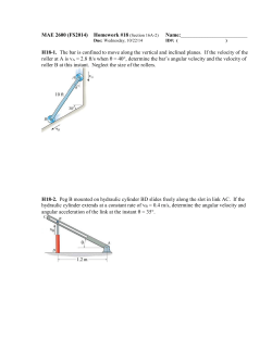
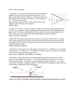
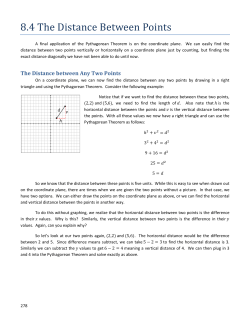
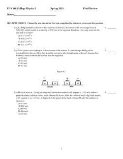
29 | P a g e A Novel Mechatronic Approach for Functional Recovery of Human Locomotion MUHAMMAD KAMRUL HASAN , JANG-HO PARK ,SE1 KYOUNG YOUM ,SEUNG-HUN PARK 3 2, 1 ABSTRACT sensor input to generate motor outputs appropriate for Objective: To retain the locomotive ability after neurological or orthopaedic impairments, consistent and functional training should be emphasized to recover the motor function of the extremities. The aim of this study is to develop a novel mechatronic approach in which kinematics and kinetics of human locomotion have been incorporated into an optimum motion algorithm for robotenhanced gait rehabilitation. Methods: Our mechatronic system has two personalized, gait trajectory guided and programmable footboards equipped with force sensors. First, human locomotion was analysed to generate personalized gait parameters, using various gait databases. Then, dynamic motions were modelled to be programmed in the system. Finally, we implemented the dynamic motion models to a gait trajectory guiding device for simulating precise, subject-oriented and smooth motion. Results: The mechatronic system simulated varied stride length, step time and its distribution among double and single support phase, according to the patient's height and average walking velocity. As the walking speed increases, the duration of double support phase approached zero. Horizontal velocity, the values of z1F (t), z2F (t) and their corresponding velocities presented different phases of the walking cycle on the backward and forward plates of the device. Conclusions: By changing the values of patient's height and velocity, we can simulate person-specific, ideal trajectory for the foot-boards. In conclusion, our developed system is an automated tool that can provide patients a natural walking practice and also guide them to follow an ideal pressure distribution and postural control through visual biofeedback. stepping [3]. So far, a small number of people around the KEY WORDS: 1 U-Health Lab, Department of Biomedical Engineering, Kyung-Hee University, South Korea; 2Medical IT Convergence Research Centre, Korea Electronics Technology Institute, South Korea; 3Industry-Academic Cooperation Foundation, Dongguk University, South Korea Received 14 June 2015 Accepted 15 August 2015 Introduction For rehabilitation to be effective in helping an individual to regain optimal functional recovery, more emphasis should be placed on encouraging the use of injured limbs and providing task-focused experience and training [1]. There is a lot of evidence that neural reorganization reflects patterns of use. Even at the peripheral level, an exercise program with a specific goal has been shown to enhance recovery in both acute and chronic neuropathies. For retaining the walking ability, a task-specific repetitive approach has proven to be an effective measure for gait rehabilitation of no-ambulatory hemi-paretic patients [2]. It is hypothesized that the technique works in part by stimulating the remaining force, position, and touch sensors in the legs during stepping in a repetitive manner and that residual circuits in the nervous system learn from this world have worked with gait rehabilitation devices based on gait trajectory guided foot-boards [4-7]. However, some gait rehabilitation devices have limitations. Neurological Rehabilitation Gait pattern simulation Patient-specific walking database Gait trajectory guiding device Correspondence to: Dr Se-Kyoung Youm Email: [email protected] The design of the existing devices have problems in simulating realistic walking patterns; some of the devices do not consider the variations in walking patterns of peoANNALS OF MEDICAL AND BIOMEDICAL SCIENCES. 2015; 1 (2): 29-36 30 | P a g e ple of different ages, height, gender. Researchers have During the training session, we need to collect feedback suggested designs with unnecessary sophistication which from the subject continuously through the pressure sensors have made the ultimate devices complex, large in size and mounted on the foot-boards for analysing how the subject expensive for mass installation. Researchers have suggest- is reacting to the foot-boards, the change in the centre of ed unnecessarily sophisticated designs, which resulted in pressure (COP) and the improvement of the training over large and expensive devices for mass production and easy time. In retraining gait in patients with walking disability, installation. Aiming for a device for recovery of locomo- having a percentage of their body weight supported results tive function, we have designed and developed an auto- better walking abilities than gait training while the pa- mated mechatronic system that uses computer simulated, tients bear their full weight [8]. The harness provides sup- gait trajectory guided foot-boards. Two hypotheses have port for the patient‘s pelvis and trunk during the gait cy- led us to this work. First, if we can study a patient while cle. That is why a suspension system for supporting the suspended from a body-weight support harness with partial weight of a subject is important. It should also have his/her feet on guided foot boards, a patient‘s other joints proper adjustments for varying the weight support accord- like ankles and knees can also be studied to obtain a real- ing to the subject‘s acuteness of disability and pressure- istic gait pattern in different phases of a complete walking feedback from the foot-boards. Finally, as the motion con- cycle. Second, allowing the legs to move freely in differ- trol and synchronization of this system need a computer, ent degrees of freedom is more effective for optimal mus- the software interface should be comprehensive and user- cular activation during the guided training that can help friendly so that physiotherapists can operate it with ease. the patient regain his/her normal walking. In our gait tra- The software system should store all the training histories jectory guiding device, we have simulated the walking of patients and show them both in tabular and graphical pattern on two mechanized foot-boards where the subject forms. It should also have some built-in intelligence to will place their feet during the training session and a ther- generate some further training prescription, analysing the apist will supervise the total training session for control- history of the patients. ling the paretic limb. Also, the foot-boards must have the provisions of multidimensional movement both horizon- Materials and methods tally and vertically with adequate degrees of freedom and Personalized Human Locomotion Analysis variable velocity for supporting the total simulation of While analysing various kinds of gait databases [9-10] and natural gait pattern of a normal subject in design ap- previous research works regarding natural walking pat- proach. First of all, we concentrated on developing an terns, [11-13] our major focus was to interpret those data optimal motion algorithm for the foot-boards to accom- and research outcomes in terms of our planned mechatron- modate patients of different ages, heights and genders, the ic system. We have reached the following observations design has to be quiet, cost-effective and compact so that from these analyses- (1) With respect to the sagittal plane, the device can be easily installed in any physiotherapy foot trajectory can be expressed by vector 𝑇𝑓 = [𝑥𝑓 (𝑡), 𝑧𝑓 centre or infirmary without making any extra arrange- (𝑡), 𝜃𝑓 (𝑡)] T, T where (𝑥𝑓 (𝑡), 𝑧𝑓 (𝑡)) represents the coordi- ments or structure. Each footplate should be controlled for nate of the heel position and 𝜃𝑓 (𝑡) denotes the angle of swing speed to get smooth motion when the motion direc- the foot. That is why from our perspective of gait simula- tion has to change. To obtain smooth and precise motion tion in foot-boards vertical elevation, horizontal progres- from the plates, sufficient sensors have been installed to sion of heel and angle of feet during walking are three control the motion at each degree of freedom. Every me- very important parameters. (2) Though normal human chanical device shows different kind of kinetic or static locomotion is a series of recurring movement with the inertia for different loads. These sensors help the foot- natural period of locomotion cycle, walking is possible at boards to correct their motion in each step through an iter- a wide variety of combinations of step length 𝑠𝑙 and step ative learning algorithm and follow the actual gait trajec- frequency 𝑠𝑓 (𝑣𝑒𝑙𝑜𝑐𝑖𝑡𝑦 𝑣 = 𝑠𝑙 × 𝑠𝑓). Inman et al. [12] have tory. suggested an empirical formula by linearly relating the ANNALS OF MEDICAL AND BIOMEDICAL SCIENCES. 2015; 1 (2):29-36 31 | P a g e stride lengths 𝑠𝑙 with body height h of a person: 𝑠𝑙 = 0.004 swing phase can be calculated. Due to step symmetry, × 𝑠𝑓 × h, where 𝑠𝑙 and h are measured in meter and 𝑠𝑓 in same velocity patterns will be implemented in the back- steps/minute. This equation can be re-written in terms of warding foot-board during its Single Support Phase. average velocity of walking 𝑠𝑙 = 0.004 v h . (3) Moving average trend line for the horizontal distances between Dynamic Motion Planning for Foot-Platform feet over time follows an almost sinusoidal nature. This is To simplify implementation of our mechatronic system, called step symmetry. This property of human locomotion we have changed the trajectory vector 𝑇𝑓 = [𝑥𝑓 (𝑡), 𝑧𝑓 (𝑡), means that the forwarding and the back-warding foot- 𝜃𝑓 (𝑡)]T to 𝑇𝐹 = [𝑥𝐹 (𝑡), 𝑧1𝐹 (𝑡), 𝑧2𝐹 (𝑡)]T which supports boards should travel the same length of path, for the same all the components of Tf. Figure 1 (a) shows the various duration with the same horizontal velocity pattern. (4) walking parameters and 1(b) depicts the adopted axis con- Stance phase of a gait cycle comprises of two double limb figuration of the foot-boards based on vector T F. support intervals and one single limb support [11]. For maintaining step symmetry, the variable horizontal velocity pattern should be the same for both foot-boards. In oth- Figure 1. (a) Parameters of Human Locomotion, (b) Axisconfiguration of the Foot-Boards based on Parameters of Human Locomotion. er words, gait cycle should be equally divided between the forward and backward progression. The foot placed on the forwarding foot-boards should act as Swing limb and at the same time Single limb Support Phase will be simulated in the back-warding plate. (5) The Double Support Phase starts with the initial loading of one foot and continues until the other foot terminates the pre-swing phase. That is why Double Support Phase should be simulated in both foot-boards at the same time for the same duration. Inman et al. [12] has established another linear relationship between the step frequency and the duration of the double support state tds as a percentage of a gait cycle time period 𝑡𝑐𝑦𝑐𝑙𝑒 based on experimental data: 𝑡𝑑𝑠 = −0.16 × 𝑠𝑓 + 29.08 × 𝑡𝑐𝑦𝑐𝑙𝑒, where 𝑡𝑐𝑦𝑐𝑙𝑒 = 2 × 𝑡𝑠𝑡𝑒𝑝 = 2𝑠𝑓. The horizontal displacement for both feet during the Double Support Phase is quite insignificant and therefore can be ignored. However, during double support phase both foot-boards have motion in vertical direction. (6) During the swing Defining the values of the components of T f with respect phase the horizontal velocity follows an elliptical shape to time and the variable velocity patterns along X, Z1 and 𝑉h𝑜𝑟𝑧 (𝑡) = b (1 t / a ) where, a and b represents the X Z2 directions based on the anthropometric parameters of a and Y-axes intercepts respectively. After integration we subject are the two major challenges for simulating walk- can determine that, ing in a task specific repetitive manner for motor relearn- b t a2 t 2 a2 t ( sin 1 ) 2 2 a 𝑥𝑓 (𝑡) = a ing. Assuming the period necessary for one walking step 2 2 2 (1) From user input of step frequency or average velocity and height of particular subject, the value of x and step duration (𝑡𝑚𝑎𝑥 = 𝑥 / 𝑎𝑣𝑒𝑟𝑎𝑔𝑒 𝑣𝑒𝑙𝑜𝑐𝑖𝑡𝑦) can be calculated. Plugging the value of x = step length, t = a = tstep – tds in (1), elliptical shape of the horizontal velocity pattern and acceleration for the forwarding foot-board during the ANNALS OF MEDICAL AND BIOMEDICAL SCIENCES. 2015; 1 (2): 29-36 is tstep, the time for nth step is from n. tstep to (n+1). tstep, where n=1, 2, 3… N, N is the number of step. Empirical equations discussed before for finding step length shows that, if a velocity is defined, a subject specific step length and step frequency can be determined. Value of sl is equal to xF (t) at t = n.tstep. Previous research on gait analysis also suggests that, at heel strike or initial contact, the Met- 32 | P a g e atarsophalangeal (MP) joint is in 250 dorsiflexion with the Design and Development of the Mechatronic System toes up, followed by a total contact with the ground at the The important aspects that a gait trajectory guiding device end of the loading response- the toes drop towards neutral should have are simulating precise, subject-oriented, alignment and maintain this position throughout mid smooth motion through the foot-boards that replicate the stance. With heel rise in terminal stance, the MP joint dor- natural human gait trajectory with sufficient degrees of 0 siflexes up to 20 . This motion continually increases freedom and the capability to support the weight of a throughout pre-swing to a f position of 700 extension [11]. moving human body. From a gait study we know that 40 Based on these findings, we can model the values of θf (t) percent of a normal gait cycle consists of a single-support with respect to time which leads us to find the values of phase. When the heel strikes the ground while shifting the z1F (t) and z2F (t). Figure 2(a) indicates the modelled θf (t) pressure from one foot to another, the corresponding foot on the basis of the foot-angle derived from the coordinate strikes the ground with about 10% more vertical force data of [10]. Figure 2(b) shows the simulation of foot- than the subject‘s weight [10]. With that in mind, our goal boards trajectory in forward and backward progression was to design a system that has driving motors of the foot- cases on the basis of the modelled angle. From the length boards corresponding to different axes to support the re- of the foot-board, modelled angle values and % duration quired torque with necessary tolerance limit. One of the of different phases of a complete walking cycle suggested major design goals was to keep the system simple but in [11], values of z1F (t)and z2F (t) for t= n.tstep to (n+1). suitable for the best interaction between a patient and a tstep can be easily calculated. therapist. The main concern regarding the mechanical Figure 2. (a) Data modelling for foot-board angles over design was to find out how to support all the kinematic time, (b) MATLAB simulation of foot-plate movement for features such as horizontal and vertical displacements and our gait trajectory during device according to modelled velocities of human locomotion. In designing the system, walking we tried to incorporate all of our goals for the perfect de- parameters. frames/sec for figure (a). Sampling frequency = 69.9 sign. The base of the system consists of two plates placed parallel to each other. A horizontal screw is positioned in each plate in the longitudinal direction. Rotation of the motor coupled with a horizontal screw will provide the foot-board-holders motion along the x-axis. Each of the foot-board-holders contains two vertical guide ways with vertical screws in the Z1 and Z2 axes. Rotation of the motors connected to the vertical screws render upward and downward movements of the foot-boards along the Z1 and Z2 axes. In summary, movement of each foot-board along the three axes X, Z1 and Z2 is accomplished by three motors with one horizontal and two vertical screws placed in the guide ways. To overcome the inertia variability to which the motors are subject due to an uneven load distribution during different phases of a gait cycle, we have used the data provided by motor encoders and photoelectric motion sensors to keep track of the foot-boards moving along the axes, so that we can check the motion in the desired gait trajectory. After a thorough analysis of motion pattern, we installed three sensors along the x-axis movement and two sensors at two ends of the Z1 and Z2 guide ways. In addition to these motion sensors, four load-cell ANNALS OF MEDICAL AND BIOMEDICAL SCIENCES. 2015; 1 (2):29-36 33 | P a g e pressure sensors were also mounted on each foot-board. graphs in Figure 4(b) depict that as the walking speed in- During a training session our software continuously takes creases, the duration of double support phase approaches information from the pressure sensors to read the patient‘s zero. Simulating such a time division in a heavy mechani- progress and produces a graph so that therapists can make cal device may be difficult. a better training strategy. The data obtained are used to Figure 4. Variability of (a) Stride Length, (b) Step Length with Body Height and Average Walking Velocity. control the motor of the Body-Weight Support Suspension System for varying the percentage of weight support. Figure 3 shows a comprehensive overview of the system. Figure 3. Overview of the Complete System. However, we can use the personalized walking parameters by using the ratio of step time distribution among double and single support phases. Table 1 shows the elliptical shape of horizontal velocity Results With the software input of patient‘s height and desired average speed of walking, the first task is to determine the stride length of the subject. From the stride length and average speed, the other parameters, such as Step Length, Step Frequency, Step Time, Double Support Phase Time, Single Support Phase Time, elliptical shape of the horizontal velocity pattern, vertical velocity variation in Z1 and Z2 directions with respect to time can be determined. The parameters should be controlled at certain limits to keep the parameters within anatomical limits defined by locomotion attribute e.g. sfmax = 182 step/min or slmax= 1.08m [13]. Figure 4(a) shows the Stride Length Variability with Body Height and Average Walking Velocity, and Figure 4(b) describes how step time and its distribution among the double and single support phase vary in terms of Body Height and average horizontal velocity. The ANNALS OF MEDICAL AND BIOMEDICAL SCIENCES. 2015; 1 (2): 29-36 and the values of z1F (t), z2F (t) and their corresponding velocities for simulating different phases of a walking cycle on the backward and forward plates of the device. This calculation was done on a subject of height = 1.8m and the desired walking speed = 5kmph. In Figure 5(a) and 5(b), the shapes of the horizontal and vertical velocities are shown with references to original velocity patterns derived from sample data [10]. By changing the values of the subject‘s height and velocity, we can simulate personspecific, ideal trajectory for the foot-boards. The modeled velocity in Figure 5(a) during swing phase shows some discrepancies in the original velocity of the sample data. Although we considered horizontal velocity as insignificant before toe-off and after the heel-strike, this graph shows some horizontal velocity in those regions. 34 | P a g e Figure 5. Model data of (a) Horizontal velocity along X of the upward velocity of feet along Z1 or Z2 direction. axis and (b) Vertical velocity of foot-boards along Z1 and These horizontal components have also contributed to the Z2 axes in comparison with original velocities of foot sample data velocity measured during the swing phase. from a sample data. Modelled velocity VX, VZ1 and VZ2 That is why the modeled velocity in Figure 5(a) appears were calculated considering v = 5kmph and body height = smaller than the original one. In addition to speed and 1.8m. Sampling frequency = 69.9 frames/sec. position control of the motor, speed-pulse output information from the motor encoder proved to be useful when setting the footplates in the initial position, controlling the motion. Figure (6) presents Speed-Pulse output information from one of the two horizontal motors. Variability of the duty cycles of this pulse shows how variable speed has been implemented for horizontal movement of the footplate. Table 1. Velocity Pattern (For Body Height = 1.8m and Average Walking Velocity = 5kmph) Length of Foot-Boards of the device = 25.4 cm X Axis Intercept for Elliptical Shape of Horizontal Velocity = a = 0.48 Y Axis Intercept for Elliptical Shape of Horizontal Velocity = b = 2.04 tstep= 0.56, tds = 0.07, tss = 0.48 Time Angle B P M A-B B-C C-D D-E t_ds 1/2 of t_ss 1/2 of t_ss t_ds 0.074 0.242 0.242 0.074 F P M E-EF 1/3 of t_ss 0.159 EF-F 1/3 of t_ss 0.159 F-G 1/3 of t_ss 0.159 Time -25 to 0 0 0 0 Ascend 4 cm from gnd Descend 4 cm from gnd -10.72 0 0 0 -1.45 0 0 0 4 0.250 -4 -0.250 0 to -25 10.72 0.671 Angle B A-B t_ds 0.074 P B-C 1/2 of t_ss 0.242 M C-D 1/2 of t_ss 0.242 F D-E t_ds 0.074 P E-F 2/3 of t_ss 0.319 M F-G 1/3 of t_ss 0.159 BPM: Backward Plate Movement, FPM: Forward Plate Movement Vz1F (ms-1) z1F (cm) 0 0 0 to 20 20 to 70 70 to 0 0 z2F (cm) 0 0 8.68 15.17 -23.86 0 Vz2F (ms-1) 0 0 0.358 2.056 -0.747 0 ANNALS OF MEDICAL AND BIOMEDICAL SCIENCES. 2015; 1 (2):29-36 35 | P a g e Figure 6. Elliptical Horizontal Velocity Pattern (output taken from Speed-Pulse output information of servo encoder). The second pulse output represents the zoomed version of the first pulse-train in each picture. Discussion kinds of gait patterns and simulate them so that after being In a gait trajectory guiding device, apart from being co- trained with our system, a patient can acquire all the ca- herent with the patient-specific perfect gait pattern, pre- pacities to perform basic activities of daily living. Fur- cise time division of the total movement is necessary for thermore, as we will collect patients’ biofeedback infor- keeping track of a patient‘s biofeedback in different phas- mation from all of their training sessions through our ver- es of the cycle. Although the Ground Contact Force tical ground reaction force measurement system and store (GCF) signals do not directly provide feedback signals for them, this will help us to include a knowledge-based phys- controlling assistive devices, they do provide a foundation iotherapeutic system which can set optimal training algo- for detecting human motion phases and enable assistive rithms for individual patients. devices to adaptively change the algorithms for each motion phase for better estimation of the feedback signals [14]. They will also be used for reducing tracking errors by a trial-and-error procedure. After each repetition of the Conflict of Interest We declare that we have no conflict of interest. References gait cycle the feed-forward control signal can be improved by some learning rule. The photoelectric motion sensors 1 installed along every axis of movement and encoders inside the Servo Motor will provide the speed and position 2 information. Conventional therapy requires a lot of physical efforts from at least two therapists to set the paretic 3 limbs and to control the trunk movement of a neurologically disabled patient. When physiotherapists have to work in uncomfortable positions that require a lot of physical exertion, they may find it difficult to treat patients. 4 Our system is an automated tool that can assure patients a natural walking practice and also guide them to follow an 5 ideal pressure distribution and postural control through visual biofeedback. For returning back to a normal life after neurological rehabilitation, it is also important for 6 everyone to restore a full-fledged gait ability. The mechanical architecture of our system also allows us to simulate walking on uneven ground, perturbed gait and stair walking. In later phase we will extend our study to these ANNALS OF MEDICAL AND BIOMEDICAL SCIENCES. 2015; 1 (2): 29-36 7 Carr J, Shepherd R. Neurological Rehabilitation: Optimizing Motor Performance. 2nd ed. Oxford: Butterworth Heinemann; 1998. Asanuma H, Keller A. Neurobiological Basis of Motor Learning and Memory. Concepts Neurosci. 1991; 2(1): 1–30. Wang CE, Bobrow JE , Reinkensmeyer DJ. Swinging From The Hip: Use of Dynamic Motion Optimization in the Design of Robotic Gait Rehabilitation. IEEE Int Conf Robot. 2001; 1433-1438. Schmidt H, Werner C, Bernhardt R, Hesse S, Krüger J. Gait Rehabilitation Machines based on Programmable Footplates. J Neuroeng Rehabil. 2007; 4(2). Roston PG, Peurach T. A Whole Body Kinesthetic Display Device for Virtual Reality Applications. IEEE Int Conf Robot. 1997; 3006-3011. Merians AS, Jack D, Boian R, Tremaine M, Burdea GC, Adamovich SV, Recce M, et al. Virtual Reality – Augmented Rehabilitation for Patients Following Stroke. Phys Ther. 2002; 82(9): 898915. Yano H, Iwata H, Noma H, Miyasato T. Shared Walk Environment Using Locomotion Interface. ACM Conf CSCW. 2000; 163-170. 36 | P a g e 8 Visintin M, Barbeau H, Korner-Bitensky N, Mayo NE. A New Approach to Retrain Gait in Stroke Patients through Body Weight Support and Treadmill Stimulation. Stroke. 1998; 29(6): 1122–1128. 9 Out L, Harlaar J, Doorenbosch C. MoXie Viewer—XML-based Sharing of Movement Analysis Results. Gait Posture. 2006; 24(2): 136-137. 10 Winter DA. Biomechanics and Motor Control of Human Movement. 3rd ed. John Wiley and Sons, Inc.; 2005. 11 Perry J. Gait Analysis: Normal and Pathological Function. Thorofare, NJ: Slack Inc.; 1992. 12 Inman VT, Ralston HJ, Todd F. Human Walking. Baltimore Williams & Wilkins; 1981. 13 Bruderlin A, Calvart TW. Goal-Directed, Dynamic Animation of Human Walking. Comp Graph. 1989; 23(3): 233-242. 14 Kong K, Tomizuka M. Smooth and Continuous Human Gait Phase Detection Based on Foot Pressure Patterns. IEEE Int Conf Robot. 2008; 3678-3683. ANNALS OF MEDICAL AND BIOMEDICAL SCIENCES. 2015; 1 (2):29-36
MUHAMMAD KAMRUL HASAN, JANG-HO PARK, ,SE-KYOUNG YOUM, SEUNG-HUN PARK, AMBS Objective: To retain the locomotive ability after neurological or orthopaedic impairments, consistent and functional training should be emphasized to recover the motor function of the extremities. The aim of this study is to develop a novel mechatronic approach in which kinematics and kinetics of human locomotion have been incorporated into an optimum motion algorithm for robotenhanced gait rehabilitation. Methods: Our mechatronic system has two personalized, gait trajectory guided and programmable footboards equipped with force sensors. First, human locomotion was analysed to generate personalized gait parameters, using various gait databases. Then, dynamic motions were modelled to be programmed in the system. Finally, we implemented the dynamic motion models to a gait trajectory guiding device for simulating precise, subject-oriented and smooth motion. Results: The mechatronic system simulated varied stride length, step time and its distribution among double and single support phase, according to the patient's height and average walking velocity. As the walking speed increases, the duration of double support phase approached zero. Horizontal velocity, the values of z1F (t), z2F (t) and their corresponding velocities presented different phases of the walking cycle on the backward and forward plates of the device. Conclusions: By changing the values of patient's height and velocity, we can simulate person-specific, ideal trajectory for the foot-boards. In conclusion, our developed system is an automated tool that can provide patients a natural walking practice and also guide them to follow an ideal pressure distribution and postural control through visual biofeedback. KEY WORDS: Neurological Rehabilitation Gait pattern simulation Patient-specific walking database Gait trajectory guiding device
© Copyright 2026 Paperzz