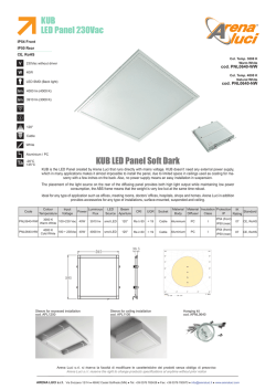
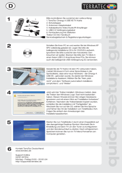
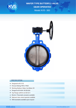
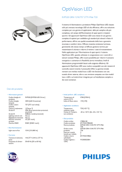
®
Blade® 350 QX Firmware 2.0 Update and Quick-Start Guide
This Blade 350 QX has been updated with Firmware 2.0 to provide the best experience. This slipsheet covers the updates and includes a new Quick-Start Guide.
New Start Procedure
There are now two options to start the motors:
Original Procedure: At zero throttle, move the rudder stick full left, then full right, then back to center.
New Procedure: Move both sticks into the bottom inside corners, then back to center.
New Flight Mode Configuration
Smart Mode (Solid Green LED = GPS Lock, Blinking Green LED = No GPS Lock): Stick Relativity, SAFE Circle™ feature, Altitude and GPS Lock and Self-Leveling
AP Mode (Solid Purple LED = GPS Lock, Blinking Purple LED = No GPS Lock): Altitude and GPS Lock with soft Self-Leveling
Stability Mode (Solid Blue LED = GPS Lock, Blinking Blue LED = No GPS Lock): Self-Leveling, GPS Lock
*Agility Mode (Red LED): Only available with Spektrum™ DX6i or higher transmitters (Endpoint adjustment is necessary)
New Compass and GPS Error Detection
The Firmware 2.0 update prevents GPS and compass errors from causing adverse flight conditions. The status LED blinks orange if the compass senses a magnet or metal object
nearby. When the status LED blinks orange, follow the Compass Calibration instructions found in the full manual online at www.horizonhobby.com.
New Charger
This version comes with a new 12V DC accessory charger that plugs into a 12V auxiliary power port, like the one found in your car. This charger functions exactly the same as the
original charger but has a 12V DC accessory power connector instead of DC alligator clips.
Quick-Start Guide
WARNING: This quick-start guide is only intended to cover the basic operation of the 350 QX in Smart Mode. For a complete description of the function,
capabilities and maintenance of the Blade 350 QX, please see the full manual online at www.horizonhobby.com.
Box Contents
• Blade® 350 QX Firmware 2.0
• Camera Mount
• 3S 11.1V 2200mAh Li-Po Battery Pack
• 2–3S DC Li-Po Balancing Charger
• DX5e DSMX® 5-Channel Transmitter (RTF only)
• 4 AA Batteries (RTF only )
Charging the Flight Battery
1. Connect the charger to an appropriate 12V DC auxiliary power port. A beep
sounds and the green LED blinks.
2. Turn the control on the amps selector so the arrow points to 2.0 amps.
DO NOT change the charge rate once the battery begins charging.
3. Move the cell selector switch to 3-cell.
4. Connect the balancing lead of the battery to the 3-cell (4 pin) charger port
and press the Start button to begin battery charging.
5. The red LED blinks, indicating charging. When the battery nears full charge,
the red and green LEDs blink, indicating cell balancing.
6. Disconnect the battery when a beep sounds and the green LED glows solid.
7. Install the flight battery (see illustration).
Install the battery
4
3
2
1
EN
Transmitter Setup (BNF)
CAUTION: When using a Futaba transmitter with a Spektrum DSM module, you must reverse the throttle channel and rebind. Refer to your Spektrum module manual for binding and failsafe instructions. Refer to your Futaba transmitter manual for instructions on reversing the throttle channel.
Transmitter
Model
Type
Reverse
Setup
Throttle Mode Setup
Cut Setup
DX4e (New)*
w/3-position
switch
N/A
N/A
N/A
N/A
DX5e (New)*
w/3-position
switch
N/A
N/A
N/A
N/A
Acro
THRO-N
ELEV-N
GEAR-R
AILE-N
RUDD-N
FLAP-N
DX6i
DX7/7SE
DX7S
DX8
Acro
Acro
Acro
DX9/DX18
Acro
FLAP-R (6)
Others-N
AUX1-R
Others-N
AUX1-R
Others-N
AUX1-R
Others-N
ACT
N/A
Set To:
Trainer
Set To:
Trainer
Set To:
I (BIND)
Travel Adj: GEAR POS (0) GEAR: ↑100%;
GEAR/F MODE POS (1) GEAR: ↓40%
FLAPS: Norm ←↑100; LAND ↓100
MIX 1: ACT; GEAR → GEAR ACT
RATE D 0%; U + 100%
SW MIX TRIM INH
SUB TRIM THRO
↑ 15-20%
Travel Adj: GEAR (0)↑100%;
GEAR (1) ↓40%
MIX 1: FLAP → Gear OFF/ON
RATE → -50%
0%
SW: MIX OFFSET: 0
Switch Select:
Move Gear to F MODE (F MODE:GEAR)
Leave FLAPS as AUX1
Set All Others to INH
MIX 1: GER > GER
RATE:
0%
-100%
OFFSET: 0%; TRIM: INH; SW: Mix0
Switch Select: F-Mode to Gear;
Flap to Aux 1
All Others to INH
Channel Assign: NEXT
1-4: N/A
5 Gear: B
6 AUX1: D
7 AUX2: I
8-10: INH
Switch Positions
Throttle Cut
Return Home
Position 0 = SMART Mode
Position 1 = AP Mode
Position 2 = Stability Mode
Position 0 = SMART Mode
Position 1 = AP Mode
Position 2 = Stability Mode
Lower throttle
trim until motors
stop turning
Lower throttle
trim until motors
stop turning
GEAR 0; Mix 0 = SMART Mode
GEAR 1; Mix 0 = AP Mode
Press throttle cut
GEAR 1; Mix 1 = Stability Mode
GEAR (0);
Mix (0) = SMART Mode
GEAR (1);
Mix (0) = AP Mode
GEAR (1);
Mix (1) = Stability Mode
Lower throttle
trim until motors
stop turning
Dual Rate
Switch
High
Rate
Low
Rate
Press and Hold
TRAINER/BIND
Release to EXIT
Rate
100%
fixed
70%
fixed
Press and Hold
TRAINER/BIND
Release to EXIT
Rate
100%
fixed
70%
fixed
ELEV-AIL D/R 100%
70%
ELEV-AIL D/R 100%
70%
ELEV-AIL D/R 100%
70%
ELEV-AIL D/R 100%
70%
ELEV-AIL D/R 100%
70%
FLAP Position 0
= OFF
FLAP Position 1 =
Return Home
FLAP Pos 0
= OFF
FLAP Pos 1
= Return Home
F MODE (0) = SMART Mode
F MODE (1) = AP Mode
Press
Trainer
FLAP Pos 0 = OFF
FLAP Pos 2 =
Return Home
F MODE (1);
HOLD (1) = Stability Mode
F MODE (0) = SMART Mode
F MODE (1) = AP Mode
Press Trainer/
Bind
F MODE (2) = Stability Mode
B (0) = SMART Mode
B (1) = AP Mode
Press I (BIND)
B (2) = Stability Mode
FLAP Pos 0
= OFF
FLAP Pos 2
= Return Home
D (FLAP) Pos 0
= OFF
D (FLAP) Pos 2 =
Return Home
* Old versions of the DX4e and DX5e (with 2-position channel 5 switches) are not recommended for the 350 QX. Only Smart Mode and Stability Mode will
be available with GPS On.
Binding (BNF)
1.
2.
3.
4.
5.
6.
With the transmitter and quadcopter powered OFF, connect the battery to the 350 QX.
With the 350 QX on a level surface, turn ON the power switch and allow the quadcopter to initialize.
Wait until the blue LED on the quadcopter flashes rapidly, signaling the quadcopter is initialized and ready to bind.
Ensure throttle is in the low position, throttle trim is at neutral and the Flight Mode Switch is set to SMART Mode.
Press/pull the bind button/switch and power ON the transmitter.
Release the bind button/switch when the LED turns solid green.
Powering On
1. Power ON the transmitter.
2. Set the Rate Switch to Hi.
3. Set the Channel 5 Switch to 0 for Smart Mode.
4. Fully lower the throttle stick.
5. Place the 350 QX on a level surface outside with the status LED towards you.
6. Power ON the 350 QX.
7. Step back approximately16 feet (5 meters).
8. Ensure the status LED is solid green, indicating GPS lock.
9. Move the rudder stick full left, then full right, then back to center, setting the Home position and starting the motors.
10. Increase the throttle stick to begin flying.
EN
Flying
Stick Relativity
Smart Mode Altitude Control
Mode 2 shown
Maximum altitude
(approximately 45 meters)
Aileron input
Left
Right
Elevator input
Forward
Back
Aircraft response
relative to the pilot
location
Aircraft response
relative to the pilot
location
SAFE Circle
Full throttle
Half throttle
Low throttle
Intermediate altitude
On the ground
Landing
Activating Return Home
1. There are two options for landing:
• Fully lower the throttle stick to land and lower
the throttle trim to stop the motors.
• Press and hold the Return Home Switch
until the aircraft has landed (see illustration).
2. After landing, power OFF the 350 QX.
3. Power OFF the transmitter.
4. Disconnect the flight battery.
Press and hold
Releasing the switch
will stop the Return Home
program.
TRAINER
Compliance Information for the European Union
AT
EE
IE
PL
IS
BE
ES
IT
PT
LI
BG
FI
LT
RO
NO
CZ
FR
LU
SE
CH
CY
GR
LV
SI
DE
HR
MT
SK
DK
HU
NL
UK
Declaration of Conformity
(in accordance with ISO/IEC 17050-1)
No. HH2013080502
Product(s):
BLH 350 QX RTF
Item Number(s): BLH7800A, BLH7800AM1
Equipment class: 2
The object of declaration described above is in conformity with the requirements of the specifications listed
below, following the provisions of the European R&TTE
directive 1999/5/EC, EMC Directive 2004/108/EC and
LVD Directive 2006/95/EC:
EN 300-328 V1.7.1: 2006
EN 301 489-1 V1.9.2: 2012
EN 301 489-17 V2.1.1: 2009
EN60950-1:2006+A11:2009+A1:2010+A12: 2011
EN61000-3-2:2006+A1:2009+A2:2009
EN61000-3-3:2008
EN55022:2010 + AC:2011
EN55024:2010
Signed for and on behalf of:
Horizon Hobby, LLC
Champaign, IL USA
Aug 05, 2013
Robert Peak
Chief Financial Officer
Horizon Hobby, LLC
Declaration of Conformity
(in accordance with ISO/IEC 17050-1)
No. HH2013080503
Product(s):
BLH 350 QX BNF
Item Number(s): BLH7880A
Equipment class: 1
The object of declaration described above is in conformity with the requirements of the specifications listed
below, following the provisions of the European R&TTE
directive 1999/5/EC, EMC Directive 2004/108/EC and
LVD Directive 2006/95/EC:
EN 301 489-1 V1.9.2: 2012
EN 301 489-17 V2.1.1: 2009
EN61000-3-2:2006+A1:2009+A2:2009
EN61000-3-3:2008
EN60950-1:2006+A11:2009+A1:2010+A12: 2011
EN55022:2010 + AC:2011
EN55024:2010
Signed for and on behalflf of:f
Horizon Hobby, LLC
Champaign, IL USA
Aug 05, 2013
Instructions for disposal of WEEE
by users in the European Union
This product must not be disposed of with other
waste. Instead, it is the user’s responsibility to
dispose of their waste equipment by handing
it over to a designated collections point for the
recycling of waste electrical and electronic equipment. The
separate collection and recycling of your waste equipment at
the time of disposal will help to conserve natural resources
and ensure that it is recycled in a manner that protects human health and the environment. For more information about
where you can drop off your waste equipment for recycling,
please contact your local city office, your household waste
disposal service or where you purchased the product.
Robert Peak
Chief Financial Officer
Horizon Hobby, LLC
EN
Blade 350 QX Firmware 2.0 Update und Quick-Start Anleitung
Dieser Blade 350 QX wurde auf die Firmwareversion 2.0 aktualisiert. Diese Quick Start Anleitung beschreibt die Aktualisierung.
Neuer Startvorgang
Sie haben nun zwei Möglichkeiten die Motoren zu starten:
Original Startvorgang: Bewegen Sie mit dem Gashebel auf Gas Niedrig Position den
Seitenrudersteuerhebel voll nach links, dann voll nach rechts und zurück in die Mitte.
Neuer Startvorgang: Bewegen Sie beide Steuerhebel in die unteren beiden inneren
Ecken und dann zurück in die Mitte.
Neue Flugmodekonfiguration
Smart Mode (grüne LED leuchtet = GPS-Signalempfang, grüne LED blinkt = kein
GPS-Signalempfang): Steuerknüppelorientierung, SAFE Sicherheitszone, Höhenund GPS-Positionshaltung, selbstaufrichtend
AP Mode (lila LED leuchtet= GPS-Signalempfang, lila LED blinkt =kein GPS-Signalempfang): Höhen- und GPS-Positionshaltung, gemäßigt selbstaufrichtend
Stabilätsmode (blaue LED leuchtet= GPS-Signalempfang, lila LED blinkt =kein GPSSignalempfang): GPS-Positionshaltung, selbstaufrichtend
*Agilitätsmode (rote LED): Nur verfügbar mit Spektrum DX6i oder höher Sender (da
Endpunkteinstellung notwendig)
Neue Kompass und GPS Fehlererkennung
Das Update auf die Firmware 2.0 verhindert GPS- und Kompassfehler und damit verbundene Flugfehler. Registriert der Kompass in seiner Nähe ein metallisches oder magnetisches Objekt, blinkt die Status LED gelb. Folgen Sie dann den in der Bedienungsanleitung beschriebenen Vorgang zur Kompasskalibrierung unter www.horizonhobby.com.
Neues Ladegerät
Diese Version wird mit einem DC 12 Volt Ladegerät mit 12 Volt Steckdosenanschluss
(Zigarettenanzünder wie in Autos üblich,) statt Krokodilklemmen geliefert.
Setinhalt
• Blade 350 QX Firmware 2.0
• Kamerahalter
• 3S 11.1V 2200 mAh LiPo Akku
• 2-3S 12V LiPo Balancer Lader
• DX5e DSMX 5 Kanal Sender (nur in der RTF Version)
• 4 AA Batterien (nur RTF Version)
Quick Start Anleitung
WARNUNG: Diese Quick Start Anleitung beschreibt nur die grundlegenden Funktionen des Blade 350QX im Smart Mode. Die vollständige Beschreibung aller Eigenschaften, Funktionen und notwendige Wartung lesen Sie in der Anleitung unter www.horizonhobby.com.
Laden des Flugakku
1. Schließen Sie das Ladegerät an einen geeigneten 12 Volt DC Stromanschluss an. Ein
Piepton ertönt und eine grüne LED blinkt.
2. Drehen Sie den Ampereregler auf dem Ladegerät so, dass der Pfeil auf 2.0A zeigt. Ändern
Sie NICHT den Ladestrom wenn der Ladevorgang begonnen hat.
3. Stellen Sie den Zellenwahlschalter auf 3S.
4. Verbinden Sie den Balanceranschluss des Akkus mit dem 3S (4 Pins) Ladeanschluss und
drücken dann den Startknopf um mit dem Ladevorgang zu beginnen.
5. Die blinkende rote LED zeigt den Ladevorgang an. Ist der Ladevorgang nahezu abgeschlossen, zeigen die blinkende rote und grüne LED den Balanciervorgang an.
6. Trennen Sie den Akku vom Ladegerät wenn ein Piepton ertönt und grüne LED leuchtet.
7. Setzen Sie den Flugakku ein (siehe Abbildung).
Einsetzen des Akkus
4
3
2
1
Sendereinstellungen (BNF)
ACHTUNG: Wenn Sie einen Futaba-Sender mit einem Spektrum DSM-Modul verwenden, müssen Sie den Gaskanal reversieren (umkehren) und danach das System
neu binden. Lesen Sie bitte für den Bindevorgang und programmieren der Failsafeeinstellungen die Bedienungsanleitung des Spektrum Modules. Zum reversieren
des Gaskanals lesen Sie bitte in der Anleitung des Futaba Senders nach.
Sender
Modell- Servoumtyp
kehr
Gas Aus
Einstellung
Mode Einstellung
DX4e (neu) mit
Drei-WegeSchalter
N/A
N/A
N/A
N/A
DX5e (neu) mit
Drei-WegeSchalter
N/A
N/A
N/A
N/A
Acro
THRO-N
ELEV-N
GEAR-R
AILE-N
RUDD-N
FLAP-N
DX6i
DX7/7SE
DE
Acro
FLAP-R
(Kanal 6)
Andere-N
ACT
N/A
Weg Einstellung: Gear (0)↑100%;
F MODE (1) ↓40%
FLAPS: Norm ←↑100; LAND ↓100
MIX 1: ACT; Gear → Gear ACT
RATE D 0%; U + 100%
SW MIX TRIM INH
SUB TRIM Gas
↑ 15-20%
Weg Einstellung: GEAR (0)↑100%;
GEAR (1) ↓40%
MIX 1: FLAP → Gear OFF/ON
RATE → -50%
0%
SW: MIX OFFSET: 0
Schalterpositionen
Gas Aus
Position 0 = Smartmodus
Position 1 = AP Mode
Position 2 = Stabilitätsmodus
Position 0 = Smartmodus
Position 1 = AP Mode
Position 2 = Stabilitätsmodus
Gas Trimm nach Drücken und
unten, bis die
Haltem Trainer/
Motoren anhalten Binden
Rate
100% 70%
gesetzt gesetzt
Gas Trimm nach Drücken und
unten, bis die
Haltem Trainer/
Motoren anhalten Binden
Rate
100% 70%
gesetzt gesetzt
GEAR 0; Mix 0 = Smartmodus
GEAR 1; Mix 0 = AP Mode
Gas aus
GEAR 1; Mix 1 = Stabilitätsmodus
GEAR (0);
Mix (0) = Smartmodus
GEAR (1);
Mix (0) = AP Mode
GEAR (1);
Mix (1) = Stabilitätsmodus
Klicken Sie den
GAstrimm nach
unten, nis die
Motoren still
stehen
Rückkehrfunktion Duel Rate
Schalter
FLAP Position 0
= Aus
FLAP Position 1 =
Rückkehrfunktion
Hohe
Rate
Niedrige
Rate
ELEV-AIL D/R 100%
70%
ELEV-AIL D/R 100%
70%
FLAP Pos 0
= OFF
FLAP Pos 1
= Rückkehrfunktion
Sendereinstellungen (BNF)
Sender
DX7S
Modell- Servoumtyp
kehr
Acro
Flugzeug
DX8
DX9/DX18
Flugzeug
AUX1-R
Andere-N
AUX1-R
Alle
anderen-N
Gas Aus
Einstellung
Mode Einstellung
Schalterpositionen
Schalterauswah:
Setze Gear auf F MODE
(F MODE:GEAR)
FLAPS auf AUX1
Einstellen:
Alle anderen INH
Trainer
MIX 1: GER > GER
RATE:
0%
-100%
OFFSET: 0%; TRIM: INH; SW: Mix0
Einstellung
Trainer
Schalterauswah: F-Mode auf Fahrwerk;
Klappen auf Aux 1
alle anderen INH
Aux1
Kanazuordnung: NEXT
Einstellen
Reverse alle
K1-4 nicht erforderlich
auf I
anderen
K6: D
(Binden)
Normal
K8-10 Aus
Gas Aus
Hohe
Rate
Niedrige
Rate
F MODE (0) = Smartmodus
Trainerschalter
drücken
F MODE (1) = AP Mode
FLAP Pos 0 = OFF
FLAP Pos 2 =
Rückkehrfunktion
ELEV-AIL D/R 100%
70%
F MODE (1);
HOLD (1) = Stabilitätsmodus
F MODE (0) = Smartmodus
Drücken Sie
Trainer/Binden
F MODE (1) = AP Mode
F MODE (2) = Stabilitätsmodus
B (0) = Smartmodus
K5 FW: B
K7: I
Rückkehrfunktion Duel Rate
Schalter
B (1) = AP Mode
Drücken Sie I
B (2) = Stabilitätsmodus
Klappen Pos 0
= OFF
ELEV-AIL D/R 100%
Klappen Pos 2
= Rückkehrfunktion
D (Landeklappen)
Pos 0 = Aus
D (Landeklappen) ELEV-AIL D/R 100%
Pos 2 = Rückkehrfunktion
70%
70%
* Die älteren Versionen der DX4e und DX5e mit einem Zwei-Wegeschalter werden für den Betrieb des Blade 350 QX nicht empfohlen. Hier stehen nur die Modi Smartmodus
und Agilitätsmodus mit GPS Ein zur Verfügung.
Der Bindevorgang (BNF)
1.
2.
3.
4.
5.
6.
Schließen Sie mit ausgeschaltetem Sender und Quadcopter den Akku am 350 QX an.
Stellen Sie den Blade 350 QX auf eine ebene Fläche und schalten Sie das Modell ein. Lassen Sie sich den Quadkopter initialisieren.
Warten Sie, bis den blaue LED am Heck blinkt. Es zeigt an, dass der Quakopter initialisiert hat und gebunden werden kann.
Stellen Sie sicher, dass das Gas ganz unten und die Trimmung in der Neutralstellung steht.
Halten Sie die Steuerknüppel in gewünschter Position (siehe Abbildung) und drücken/ ziehen den Bindeknopf/Schalter und schalten dann den Sender ein.
Bitte prüfen Sie anhand der Flug LED Anzeige Codes ob der Copter korrekt gebunden ist.
Einschalten
1. Schalten Sie den Sender ein.
2. Stellen Sie den Dual Rate Schalter auf Hi.
3. Stellen Sie den Kanal 5 Schalter für den Smart Mode auf 0.
4. Bringen Sie den Gashebel ganz nach unten auf Leerlauf.
5. Setzen Sie den 350QX auf eine ebene Oberfläche, so dass die Status LED zu Ihnen zeigt.
6. Schalten Sie den 350QX ein.
7. Treten Sie 5 Meter zurück.
8. Versichern Sie sich, dass die Status LED grün leuchtet und damit das GPS Signal empfangen wird.
9. Bewegen Sie den Seitenrudersteuerhebel voll nach nach links, dann voll nach rechts. Das speichert die Rückkehrposition und startet die Motoren.
10. Geben Sie Gas und beginnen zu fliegen.
Fliegen
Höhenfixierung im Smartmodus
hier Mode 2
maximale Höhe
(ca 45m)
Steuerknüppelorientierung
Nickeingabe
nach
vorne
nach
hinten
Vollgas
nach
links
Rolleingabe
Reaktion des Blade
350 QX relativ zur
Position des Piloten
nach
rechts
Reaktion des Blade
350 QX relativ zur
Position des Piloten
SAFE Circle
Halbgas
wenig Gas
mittlere Höhe
am Boden
DE
Landen
Aktivierung der Rückkehrfunktion
1. Es gibt zwei Möglichkeiten zu landen:
• Bringen Sie den Gashebel auf Leerlauf und
schalten mit der Gastrimmung die Motoren aus.
• Drücken und halten Sie den Rückkehrbutton bis
der Copter gelandet ist (siehe Abbildung).
2. Schalten Sie nach der Landung den 350QX aus.
3. Schalten Sie den Sender aus.
4. Trennen Sie den Flugakku.
Drücken und halten
Das Loslassen des
Schalters beendet die
Rückkehrfunktion.
TRAINER
Rechtliche Informationen für die Europäische Union
AT
EE
IE
PL
IS
BE
ES
IT
PT
LI
BG
FI
LT
RO
NO
CZ
FR
LU
SE
CH
CY
GR
LV
SI
DE
HR
MT
SK
DK
HU
NL
UK
Konformitätserklärung
Konformitätserklärung
Konformitätserklärung laut Allgemeine Anforderungen (ISO/IEC 17050-1:2004,
korrigierte Fassung 2007-06-15); Deutsche und Englische Fassung EN ISO/IEC
17050-1:2010
Declaration of conformity (in accordance with ISO/IEC 17050-1)
No. HH2013080502
Horizon Hobby GmbH
Christian-Junge-Straße 1
D-25337 Elmshorn
erklärt das Produkt: BLH 350 QX RTF
BLH7800A, BLH7800AM1
declares the product: BLH 350 QX RTF
BLH7800A, BLH7800AM1
Geräteklasse:
2
equipment class:
2
den grundlegenden Anforderungen des §3 und den übrigen einschlägigen Bestimmungen des
FTEG (Artikel 3 der R&TTE) entspricht, EMV-Richtlinie 2004/108/EC und LVD 2006/95/EC.
complies with the essential requirments of §3 and other relevant provisions of the FTEG
(Article 3 of the R&TTE directive), EMC Directive 2004/108/EC and LVD 2006/95/EC.
Angewendete harmonisierte Normen:
Harmonised standards applied:
EN 300-328 V1.7.1: 2006
EN 301 489-1 V1.9.2: 2012
EN 301 489-17 V2.1.1: 2009
Konformitätserklärung laut Allgemeine Anforderungen (ISO/IEC 17050-1:2004,
korrigierte Fassung 2007-06-15); Deutsche und Englische Fassung EN ISO/IEC
17050-1:2010
Declaration of conformity (in accordance with ISO/IEC 17050-1)
No. HH2013080503
Horizon Hobby GmbH
Christian-Junge-Straße 1
D-25337 Elmshorn
erklärt das Produkt: BLH 350 QX BNF
BLH7880A
declares the product: BLH 350 QX BNF
BLH7880A
Geräteklasse:
1
equipment class:
1
den grundlegenden Anforderungen des §3 und den übrigen einschlägigen Bestimmungen des
FTEG (Artikel 3 der R&TTE) entspricht, EMV-Richtlinie 2004/108/EC und LVD 2006/95/EC.
complies with the essential requirments of §3 and other relevant provisions of the FTEG (Article
3 of the R&TTE directive), EMC Directive 2004/108/EC and LVD 2006/95/EC.
Angewendete harmonisierte Normen:
Harmonised standards applied:
EN 301 489-1 V1.9.2: 2012
EN 301 489-17 V2.1.1: 2009
EN60950-1:2006+A11:2009+A1:2010+A12: 2011
EN61000-3-2:2006+A1:2009+A2:2009
EN61000-3-3:2008
EN55022:2010 + AC:2011
EN55024:2010
EN55022:2010 + AC:2011
EN55024:2010
Elmshorn,
05.08.2013
Klaus Breer
Geschäftsführer
Managing Director
EN61000-3-2:2006+A1:2009+A2:2009
EN61000-3-3:2008
EN60950-1:2006+A11:2009+A1:2010+A12: 2011
Robert Peak
Geschäftsführer
Managing Director
Horizon Hobby GmbH; Christian-Junge-Straße 1, 25337 Elmshorn
HR Pi: HRB 1909; UStIDNr.:DE812678792; Str.Nr.: 1829812324
Geschäftsführer: Klaus Breer, Robert Peak Tel.: +49 (0) 4121 2655 100 Fax: +49 (0) 4121 2655 111
eMail: [email protected]; Internet: www.horizonhobby.de Es gelten unsere allgemeinen
Geschäftsbedingungen, die in unseren Geschäftsräumen eingesehen werden können.
Ware bleibt bis zur vollständigen Bezahlung Eigentum der Horizon Hobby GmbH
Elmshorn,
05.08.2013
Klaus Breer
Geschäftsführer
Managing Director
Robert Peak
Geschäftsführer
Managing Director
Horizon Hobby GmbH; Christian-Junge-Straße 1, 25337 Elmshorn
HR Pi: HRB 1909; UStIDNr.:DE812678792; Str.Nr.: 1829812324
Geschäftsführer: Klaus Breer, Robert Peak Tel.: +49 (0) 4121 2655 100 Fax: +49 (0) 4121 2655 111
eMail: [email protected]; Internet: www.horizonhobby.de Es gelten unsere allgemeinen
Geschäftsbedingungen, die in unseren Geschäftsräumen eingesehen werden können.
Ware bleibt bis zur vollständigen Bezahlung Eigentum der Horizon Hobby GmbH
Anweisungen zur Entsorgung von Elektro- und Elektronik-Altgeräten für Benutzer in der Europäischen Union
Dieses Produkt darf nicht zusammen mit anderem Abfall entsorgt werden. Stattdessen ist der Benutzer dafür verantwortlich, unbrauchbare Geräte durch Abgabe bei
einer speziellen Sammelstelle für das Recycling von unbrauchbaren elektrischen und elektronischen Geräten zu entsorgen. Die separate Sammlung und das Recycling
von unbrauchbaren Geräten zum Zeitpunkt der Entsorgung hilft, natürliche Ressourcen zu bewahren und sicherzustellen, dass Geräte auf eine Weise wiederverwertet
werden, bei der die menschliche Gesundheit und die Umwelt geschützt werden. Weitere Informationen dazu, wo Sie unbrauchbare Geräte zum Recycling abgeben
können, erhalten Sie bei lokalen Ämtern, bei der Müllabfuhr für Haushaltsmüll sowie dort, wo Sie das Produkt gekauft haben.
DE
Blade 350 QX version 2.0 et guide de démarrage rapide
Ce Blade 350 QX possède la version 2.0 du logiciel. Ce feuillet vous présente les nouvelles fonctions et le nouveau guide de démarrage.
Nouvelle procédure de démarrage
Il y a maintenant 2 options pour démarrer les moteurs:
Procédure classique: Manche des gaz en bas, déplacez le manche de dérive totalement à gauche, puis totalement à droite et replacez le manche de dérive au neutre.
Nouvelle procédure: déplacez les 2 manches dans leurs coins intérieurs bas, puis replacez-les au neutre.
Nouvelle configuration des modes de vol
Mode Smart (DEL verte fixe = Verrouillage GPS, DEL verte clignotante= Pas de verrouillage GPS): Relativité des manches, cercle SAFE, verrouillage GPS, verrouillage de l’altitude et
stabilisation automatique
Mode AP (DEL violette fixe = Verrouillage GPS, DEL violette clignotante= Pas de verrouillage GPS): Verrouillage GPS, verrouillage de l’altitude et stabilisation automatique
Mode Stabilité (DEL bleue fixe = Verrouillage GPS, DEL bleue clignotante= Pas de verrouillage GPS): Verrouillage GPS et stabilisation automatique
*Mode Agilité (DEL rouge): Seulement disponible à partir des émetteurs Spektrum DX6i et supérieurs (Un réglage des fins de courses est nécessaire)
Détection d’erreur du compas et du GPS
La version 2.0 du logiciel permet d’éviter les conditions de vol erratiques dues à un défaut de calibration du GPS ou du compas. La DEL de statut clignote en orange si le capteur du compas
détecte à sa proximité un aimant ou une masse métallique. Quand la DEL clignote en orange, suivez les instructions relatives à la calibration du compas situées dans le manuel téléchargeable
sur www.horizonhobby.com.
Le nouveau chargeur
Cette nouvelle version est livrée avec un chargeur se connectant sur la prise allume cigare 12V de votre véhicule. Ce chargeur a un fonctionnement identique à celui de la version précédente,
la seule différence provient de sa prise allume cigare replaçant les pinces crocodile.
Guide démarrage rapide
AVERTISSEMENT: Ce guide de démarrage rapide couvre uniquement une utilisation basique du 350QX en Mode Smart. Pour des informations détaillées relatives aux fonctions et
la maintenance à effectuer sur le Blade 350 QX, veuillez consulter le manuel complet sur la page www.horizonhobby.com.
Contenu de la boîte
• Un Blade 350 QX V2.0
• Un support de caméra
• Une batterie Li-Po 3S 11.1V 2200mA
• Un chargeur équilibreur Li-Po 2-3S
• Un émetteur Spektrum DX5e DSMX 5 voies (Version RTF uniquement)
• 4 piles AA (Version RTF uniquement)
Charge de la batterie
1. Connectez le chargeur à une prise allume cigare 12V DC, un bip sera émit et la
DEL verte clignote.
2. Réglez le sélecteur d’intensité de charge sur 2A. NE PAS changer cette valeur
après le lancement de la charge.
3. Placez l’interrupteur de sélection du nombre d’éléments en position 3S.
4. Connectez le câble d’équilibrage de la batterie au port de charge pour 3
éléments (il comporte 4 broches) et appuyez sur le bouton Start pour démarrer
la charge.
5. La DEL rouge se met à clignoter, indiquant que le charge est en cours. Quand la
fin de la charge approche, la DEL rouge et la DEL verte clignotent pour indiquer
le passage en mode équilibrage.
6. Déconnectez la batterie après l’émission d’un bip et quand la DEL est verte fixe.
7. Installez la batterie dans le Blade 350 QX (Voir illustration).
Insérez la batterie
4
3
2
1
FR
Tableau de configuration émetteur (BNF)
ATTENTION : Si vous utilisez un émetteur Futaba avec un module Spektrum DSM2/DSMX, il vous faudra inverser la voie de la manette des gaz et effectuer à nouveau
l’affectation. Référez-vous au manuel d‘utilisation du module Spektrum pour les instructions d’affectation et de sécurité failsafe. Référez-vous au manuel d’utilisation de
l’émetteur Futaba pour les instructions d’inversion de voie de la manette des gaz.
Emetteur
Type de Sens des
modèle voies
Coupure Mode Setup
moteur
DX4e
(Nouvelle)*
IndispoIndispoIndisponible
Avec inter à 3 nible
nible
positions
DX5e
(Nouvelle)*
IndispoIndispoIndisponible
Avec inter à 3 nible
nible
positions
DX6i
Avion
DX7/7SE
DX7S
DX8
Avion
Avion
Avion
DX9/DX18
Avion
THRO-N
ELEV-N
GEAR-R
AILE-N
RUDD-N
FLAP-N
ACT
FLAP-R (6)
Les
autres - N
Indisponible
AUX1-R
Les
autres - N
Assignez
le bouton
Trainer
(écolage)
Positions des interrupteurs
Position 0 = Mode Smart
Indisponible
Position 1 = Mode AP
Position 2 = Mode Stabilité
Position 0 = Mode Smart
Indisponible
Position 1 = Mode AP
Position 2 = Mode Stabilité
Réglage des courses: Gear (0)↑100%;
F MODE (1) ↓40%
FLAPS: Norm ←↑100; LAND ↓100
MIX 1: ACT; Gear → Gear ACT
RATE D 0%; U + 100%
SW MIX TRIM INH
SUB-TRIM GAZ
↑ 15-20%
Réglage des courses: GEAR (0)↑100%;
GEAR (1) ↓40%
MIX 1: FLAP → Gear OFF/ON
RATE → -50%
0%
SW: MIX OFFSET: 0
Assignation des voies:
Mettre Gear en F Mode (F MODE:GEAR)
Laissez FLAPS( volets) en AUX1
Placez toutes les autres en INH
MIX 1 : GEAR >GEAR
Débattement: 0%
-100%
OFFSET: 0%; TRIM: INH; Inter: Mix0
Sélection des interrupteurs:
F-Mode > Gear (Train)
Flap (Volets) >Aux 1
Tous les autres > INH
AUX1-R
Les
autres - N
Assignez
le bouton
Trainer
(écolage)
AUX1-R
Les
autres - N
Affectation des voies: Suivant
Assignez
1-4: N/A
5 Gear: B
le bouton
6 AUX1: D
7 AUX2: I
I (BIND)
8-10: INH
GEAR 0; Mix 0 = Mode Smart
GEAR 1; Mix 0 = Mode AP
GEAR 1; Mix 1 = Mode Stabilité
GEAR (0);
Mix (0) = Mode Smart
GEAR (1);
Mix (0) = Mode AP
GEAR (1);
Mix (1) = Mode Stabilité
Coupure moteur Retour départ
Baissez le trim
des gaz jusqu’à
l’arrêt des
moteurs
Pressez et
maintenez Trainer/
Bind (Ecolage /
affectation).
Relâchez pour
quitter.
Pressez et
maintenez Trainer/
Bind (Ecolage /
affectation).
Relâchez pour
quitter.
Interrupteur Grands Petits
double-débat- débatte- débattetements
ments ments
Rate (Débatte- 100%
ment)
Fixe
70%
Fixe
Rate (Débatte- 100%
ment)
Fixe
70%
Fixe
ELEV-AIL D/R
100%
70%
ELEV-AIL D/R
100%
70%
FLAP Pos 0 = OFF
Pressez le bouton
FLAP Pos 2
ELEV-AIL D/R
trainer (Ecolage)
= Retour départ
100%
70%
ELEV-AIL D/R
100%
70%
ELEV-AIL D/R
100%
70%
Baissez le trim
des gaz jusqu’à
l’arrêt des
moteurs
FLAP Position 0
Pressez le bouton = OFF
Throttle Cut
FLAP Position 1
= Retour départ
Baissez le trim
des gaz jusqu’à
l’arrêt des
moteurs
FLAP Pos 0
= OFF
FLAP Pos 1
= Retour départ
F MODE (0) = Mode Smart
F MODE (1) = Mode AP
F MODE (1);
HOLD (1) = Mode Stabilité
F MODE (0) = Mode Smart
F MODE (1) = Mode AP
F MODE (2) = Mode Stabilité
Appuyez sur le
bouton Trainer/
Bind (Ecolage
affectation)
B (0) = Mode Smart
B (1) = Mode AP
B (2) = Mode Stabilité
Appuyez sur le
bouton I (Bind)
FLAP Pos 0
= OFF
FLAP Pos 2
= Retour départ
D (FLAP) Pos 0
= OFF
D (FLAP) Pos 2
= Retour départ
* Les anciennes versions des DX4e et DX5e (équipées d’interrupteur à 2 positions à la voie 5) ne sont pas recommandées pour l’utilisation avec le 350 QX.
Seuls les Mode Smart et le Mode Agilité seront disponibles avec le GPS activé.
Processus d’affectation (BNF)
1.
2.
3.
4.
5.
6.
En ayant l’émetteur et le quadcoptère hors tension, connectez la batterie au 350 QX.
Placez le 350 QX sur une surface à niveau, mettez-le sous tension et patientez durant son initialisation.
Patientez jusqu’au clignotement rapide de la DEL bleue, signalant que le quadcoptère est initialisé et prêt à être affecté.
Contrôlez que le manche des gaz est en position basse et que le trim des gaz est au neutre.
Maintenez les manches dans les positions du type d’affectation souhaité (Voir illustrations) et pressez/tirez le bouton/interrupteur BIND/TRAINER tout en mettant l’émetteur sous tension.
Référez-vous au tableau de code de clignotement de la DEL pour vous assurer que votre modèle est correctement affecté.
Démarrage
1. Mettez l’émetteur sous tension.
2. Placez l’interrupteur des débattements (D-rate) en position grand débattements (Hi).
3. Placez l’interrupteur de la voie 5 en position 0 pour le Mode Smart.
4. Placez le manche des gaz en position basse.
5. Placez le 350QX en extérieur sur une surface de niveau, la DEL de statut face à vous.
6. Mettez le 350 QX sous tension.
7. Reculez d’environ 5m.
8. Assurez-vous que la DEL de statut est verte fixe, indiquant un verrouillage GPS.
9. Déplacez le manche de dérive totalement à gauche, puis totalement à droite et replacez le manche de dérive au neutre afin d’enregistrer la position pour le retour automatique.
10. Augmentez les gaz pour commencer le vol.
FR
Pilotage
Relativité des manches
Contrôle de l’altitude
en Mode Smart
Mode 2 représenté
Altitude maximale
(Environ 45m)
Manche des ailerons
Gauche
Droite
Manche de profondeur
Avant
Arrière
Réponse de
l’appareil relative à
la position du pilote
Réponse de
l’appareil relative à
la position du pilote
SAFE Circle
Plein gaz
Mi-gaz
Gaz coupés
Altitude intermédiaire
Posé au sol
Atterrissage
Activer la fonction Retour départ
1. 2 options s’offrent à vous pour effectuer l’atterrissage:
• En baissant le manche des gaz pour atterrir et en
baissant le trim des gaz pour couper les moteurs.
• En pressant et maintenant appuyé le l’interrupteur
de retour automatique (Voir illustration).
2. Mettez le 350 QX hors tension après l’atterrissage.
3. Mettez l’émetteur hors tension.
4. Déconnectez la batterie.
Presser et maintenir
Relâcher l’interrupteur
annulera le Retour départ.
TRAINER
Informations de conformité pour l’Union européenne
AT
EE
IE
PL
IS
BE
ES
IT
PT
LI
BG
FI
LT
RO
NO
CZ
FR
LU
SE
CH
CY
GR
LV
SI
DE
HR
MT
SK
DK
HU
NL
UK
Déclaration de conformité
(conformément à la norme ISO/IEC 17050-1)
No. HH2013080502
Produit(s) :
BLH 350 QX RTF
Numéro(s) d’article :
BLH7800A, BLH7800AM1
Catégorie d’équipement : 2
L’objet de la déclaration décrit ci-dessus est en conformité
avec les exigences des spécifications énumérées ci-après,
suivant les conditions des directives ETRT 1999/5/CE,
CEM 2004/108/EC et LVD 2006/95/EC :
EN 300-328 V1.7.1: 2006
EN 301 489-1 V1.9.2: 2012
EN 301 489-17 V2.1.1: 2009
EN60950-1:2006+A11:2009+A1:2010+A12: 2011
EN61000-3-2:2006+A1:2009+A2:2009
EN61000-3-3:2008
EN55022:2010 + AC:2011
EN55024:2010
Signé en nom et pour
le compte de:
Horizon Hobby, LLC
Champaign, IL USA
5 août 2013
Déclaration de conformité
(conformément à la norme ISO/IEC 17050-1)
No. HH2013080503
Produit(s) : BLH 350 QX BNF
Numéro(s) d’article : BLH7880
Catégorie d’équipement :
1
L’objet de la déclaration décrit ci-dessus est en conformité avec les exigences des spécifications énumérées
ci-après, suivant les conditions des directives ETRT
1999/5/CE, CEM 2004/108/EC et LVD 2006/95/EC :
EN 301 489-1 V1.9.2: 2012
EN 301 489-17 V2.1.1: 2009
Elimination dans l’Union Européenne
Ce produit ne doit pas être éliminé avec les
ordures ménagères. Il est de la responsabilité
de l‘utilisateur de remettre le produit à un point
de collecte officiel des déchets d’équipements
électriques. Cette procédure permet de garantir
le respect de l’environnement et l’absence de sollicitation
excessive des ressources naturelles. Elle protège de plus le
bien-être de la communauté humaine. Pour plus d’informations quant aux lieux d’éliminations des déchets d’équipements électriques, vous pouvez contacter votre mairie ou le
service local de traitement des ordures ménagères.
EN61000-3-2:2006+A1:2009+A2:2009
EN61000-3-3:2008
EN60950-1:2006+A11:2009+A1:2010+A12: 2011
EN55022:2010 + AC:2011
EN55024:2010
Signé en nom et pour
Robert Peak le compte de:
Chief Financial Officer Horizon Hobby, LLC
Horizon Hobby, LLC Champaign, IL USA
5 août 2013
Robert Peak
Chief Financial Officer
Horizon Hobby, LLC
FR
Blade 350 QX Aggiornamento Firmware 2.0 e Guida Rapida
Questo Blade 350 QX è stato aggiornato con Firmware 2.0 per un’esperienza ancora migliore. Questo foglio spiega gli aggiornamenti ed include una nuova guida rapida.
Nuova procedura di avviamento
Adesso ci sono due possibilità per avviare i motori:
Procedura originale: Mettere lo stick motore a zero, muovere lo stick del timone tutto a sinistra, poi tutto a destra e poi al centro.
Procedura nuova: Muovere entrambi gli stick negli angoli interni in basso e poi di nuovo al centro.
Nuova procedura di configurazione modalità di volo
Smart Mode (LED verde fisso = con GPS, LED verde lampeggiante = senza GPS): Relatività degli stick, funzione SAFE Circle, blocco altitudine, blocco posizione GPS, self-leveling
AP Mode (LED viola fisso = con GPS, LED viola lampeggiante = senza GPS): blocco altitudine, blocco posizione GPS, self-leveling moderato
Stability Mode (LED blu fisso = con GPS, LED blu lampeggiante = senza GPS): self-leveling, blocco posizione GPS
*Agility Mode (LED rosso): Solo disponibile con Spektrum DX6i o trasmittenti con maggiori canali (regolazione della corsa massima servocomando necessario)
Nuova funzione di rivelazione errori bussola e GPS
L’aggiornamento Firmware 2.0 mira a prevenire che gli errori di GPS e bussola causino condizioni di volo problematiche. Il LED per l’indicazione dello stato lampeggia arancione quando la
bussola nota un oggetto magnetico o metallico vicino. Quando il LED per l’indicazione dello stato lampeggia arancione, seguire le istruzioni per la calibrazione della bussola che si trovano nel
manuale completo scaricabile su www.horizonhobby.com.
Nuovo caricabatteria
Questa nuova versione arriva con un nuovo caricabatteria a 12V DC che va connesso alla rete tramite un dispositivo ausiliare 12V, come quello che potete trovare nella vostra macchina. Il
caricabatteria funziona proprio nella stessa maniera del caricabatteria originale, dispone però di un dispositivo per la connessione alla rete al posto dei connettori a coccodrillo.
Guida Rapida
ATTENZIONE: Questa guida rapida è prevista per coprire solamente le funzioni basilari del 350 QX in Smart Mode. Per una descrizione completa di funzioni, capacità e
manutenzione del Blade 350 QX, si prega di consultare il manuale completo online su www.horizonhobby.com.
Contenuto della scatola
• Blade 350 QX Firmware 2.0
• Supporto fotocamera
• Batteria 3S 11.1V 2200mAh Li-Po
• Caricatore con bilanciamento 2–3S DC Li-Po
• Trasmettitore DX5e DSMX 5 canali (solo versione RTF)
• 4 batterie AA (solo versione RTF)
Caricare la batteria di volo
1. Connettere il caricatore ad un dispositivo ausiliare 12V DC adatto per la
connessione alla rete. Si sentirà un “beep” ed il LED lampeggerà verde.
2. Spostare il selettore della corrente (A) in modo che la sua freccia indichi 2A.
NON cambiare il valore della corrente quando la carica è iniziata.
3. Spostare il selettore delle celle sul numero 3.
4. Collegare il cavetto di bilanciamento della batteria alla presa di bilanciamento del caricatore adatta per le 3 celle (4 piedini), poi premere il tasto Start
per iniziare la carica.
5. Il LED rosso lampeggia indicando la carica. Quando la batteria è quasi
completamente carica, i LED rossi e verdi lampeggiano indicando il bilanciamento delle celle.
6. Disconnettere la batteria quando si sentirà un “beep” e il LED resterà
acceso verde fisso.
7. Installare la batteria di volo (vedi l’immagine).
IT
Installare la batteria
4
3
2
1
Tabella impostazioni trasmettitore (BNF)
ATTENZIONE: Quando si utilizza un trasmettitore Futaba con un modulo Spektrum DSM, è necessario invertire il canale del gas ed effettuare nuovamente il Binding.
Consultare il manuale del vostro modulo Spektrum per settare nuovamente il Bind ed il FailSafe. Consultate il manuale della vostra trasmittente per effettuare l’inversione del canale del gas.
Trasmettitore
DX4e (New)*
c/interr. a 3
posizioni
DX5e (New)*
c/interr. a 3
posizioni
DX6i
Tipo di Inversione
mocorse
dello
Spegnimento
motore
Modalità
Posizioni interruttori
Spegnimento
motore
Return Home
(Ritorno a casa)
Riduttori di
corsa
Corsa Corsa
max
min
Posizione 0 = Modo Smart
N/A
N/A
N/A
Posizione 1 = Modo AP
Abbassare il trim
motore finché i
motori non smettono di girare
Tenere premuto
TRAINER/BIND
Rilasciare per
uscire
Corsa
100%
fisso
70%
fisso
Abbassare il trim
motore finché i
motori non smettono di girare
Tenere premuto
TRAINER/BIND
Rilasciare per
uscire
Corsa
100%
fisso
70%
fisso
ELEV-AIL D/R 100%
70%
ELEV-AIL D/R 100%
70%
ELEV-AIL D/R 100%
70%
ELEV-AIL D/R 100%
70%
ELEV-AIL D/R 100%
70%
Posizione 2 = Modo Stability
Posizione 0 = Modo Smart
N/A
DX7S
DX8
Acro
Acro
Acro
DX9/DX18
N/A
N/A
N/A
Posizione 1 = Modo AP
Posizione 2 = Modo Stability
Acro
DX7/7SE
N/A
Acro
THRO-N
ELEV-N
GEAR-R
AILE-N
RUDD-N
FLAP-N
ACT
Ragolaz. corsa: Gear (0)↑100%;
F MODE (1) ↓40%
FLAPS: Norm ←↑100; LAND ↓100
MIX 1: ACT; Gear → Gear ACT
RATE D 0%; U + 100%
SW MIX TRIM INH
SUB TRIM THRO
↑ 15-20%
Ragolaz. corsa: GEAR (0)↑100%;
GEAR (1) ↓40%
MIX 1: FLAP → Gear OFF/ON
RATE → -50%
0%
SW: MIX OFFSET: 0
FLAP-R (6)
Others-N
N/A
AUX1-R
Others-N
Assegnazione canale:
Portare Gear su F MODE
(F MODE:GEAR)
Lasciare FLAPS come AUX1
Impostare
Mettere tutti gli altri su INH
su: Trainer
MIX 1: GER > GER
RATE:
0%
-100%
OFFSET: 0%; TRIM: INH; SW: Mix0
AUX1-R
Others-N
AUX1-R
Others-N
Impostare
su: Trainer
Set To:
I (BIND)
Scelta interr.: F-Mode to Gear;
Flap to Aux 1
All Others to INH
Assegnazione canale: NEXT
1-4: N/A
5 Gear: B
6 AUX1: D
7 AUX2: I
8-10: INH
GEAR 0; Mix 0 = Modo Smart
GEAR 1; Mix 0 = Modo AP
Premere throttle
cut
GEAR 1; Mix 1 = Modo Stability
GEAR (0);
Mix (0) = Modo Smart
GEAR (1);
Mix (0) = Modo AP
GEAR (1);
Mix (1) = Modo Stability
Abbassare il trim
motore finché i
motori non smettono di girare
FLAP Posizione 0
= OFF
FLAP Posizione 1 =
Return Home
FLAP Pos 0
= OFF
FLAP Pos 1
= Return Home
F MODE (0) = Modo Smart
F MODE (1) = Modo AP
Premere
Trainer
FLAP Pos 0 = OFF
FLAP Pos 2
= Return Home
F MODE (1);
HOLD (1) = Modo Stability
F MODE (0) = Modo Smart
F MODE (1) = Modo AP
F MODE (2) = Modo Stability
B (0) = Modo Smart
B (1) = Modo AP
B (2) = Modo Stability
FLAP Pos 0
Premere Trainer/ = OFF
Bind
FLAP Pos 2
= Return Home
D (FLAP) Pos 0
= OFF
Premere I (BIND)
D (FLAP) Pos 2
= Return Home
* Le vecchie versioni della DX4e e della DX5e (con l’interruttore del canale 5 a 2 posizioni) non sono consigliate per il 350 QX.
Solo lo Smart Mode e l’Agility Mode saranno disponibili con GPS ON.
La procedura di connessione (BNF)
1.
2.
3.
4.
5.
6.
Con il trasmettitore e il quadricottero spenti, collegare la batteria al 350 QX.
Con il 350 QX appoggiato su di una superficie piana, accenderlo con il suo interruttore e lasciare che si inizializzi.
Attendere finché il LED blu sul quad non lampeggia velocemente per segnalare che l’inizializzazione è finita ed è pronto per la connessione.
Assicurarsi che lo stick del gas sia in posizione minima e che il trim sia in posizione neutrale.
Tenere gli stick nella posizione desiderata per la connessione (binding) e attivare il pulsante/interruttore “bind”, quindi accendere il trasmettitore.
Fare riferimento alla tabella dei codici dei LED di volo per accertarsi che il velivolo sia connesso correttamente.
Accensione
1. Accendere il trasmettitore.
2. Mettere l’interruttore D/R in posizione Hi.
3. Spostare l’interruttore del canale 5 in posizione 0 per Smart Mode.
4. Portare completamente in basso lo stick motore.
5. Posare il 350 QX su una superficie piana all’esterno con il LED per l’indicazione dello stato puntando nella vostra direzione.
6. Accendere il 350 QX.
7. Indietreggiare per 5 metri dalla posizione base.
8. Assicurarsi che il LED per l’indicazione dello stato sia acceso verde fisso, indicando l’aggancio GPS.
9. Muovere lo stick del timone tutto a sinistra, poi tutto a destra e poi al centro per impostare la posizione base per la funzione GPS “Home” e avviare i motori.
10. Alzare lo stick motore per incominciare a volare.
IT
Volo
Relatività degli stick
Smart Mode controllo della quota
Mode 2
Quota massima
(circa 45 metri)
Comando alettoni
Sinistra
Destra
Comando elevatore
Avanti
Indietro
Risposta dell’aereo
in relazione alla
posizione del pilota
Risposta dell’aereo
in relazione alla
posizione del pilota
SAFE Circle
Motore al massimo
Motore a metà
Motore in basso
Quota inter
A terra
Atterraggio
Attivazione del Return Home
1. Ci sono due opzioni per l’atterraggio:
• Portare completamente in basso lo stick motore per atterrare e
abbassare il trim motore al minimo per disarmare i motori.
• Premere e tenere premuto l’interruttore Return Home fin quando il
quadricoptero sia atterrato (vedi l’immagine).
2. Dopo l’atterraggio, spegnere il 350 QX.
3. Spegnere il trasmettitore.
4. Disconnettere la batteria di volo.
Tenere premuto
Rilasciando l’interruttore il
programma Return Home si
arresta.
TRAINER
Informazioni sulla conformità per l’Unione Europea
AT
EE
IE
PL
IS
BE
ES
IT
PT
LI
BG
FI
LT
RO
NO
CZ
FR
LU
SE
CH
CY
GR
LV
SI
DE
HR
MT
SK
DK
HU
NL
UK
Dichiarazione di conformità
(in conformità con ISO/IEC 17050-1)
No. HH2013080502
Prodotto(i):
BLH 350QX RTF
Numero(i) articolo:
BLH7800A, BLH7800AM1
Classe dei dispositivi: 2
Gli oggetti presentati nella dichiarazione sopra citata sono
conformi ai requisiti delle specifiche elencate qui di seguito,
seguendo le disposizioni delle direttive europee R&TTE
1999/5/EC, CEM 2004/108/EC, e LVD 2006/95/EC:
EN 300-328 V1.7.1: 2006
EN 301 489-1 V1.9.2: 2012
EN 301 489-17 V2.1.1: 2009
EN60950-1:2006+A11:2009+A1:2010+A12: 2011
EN61000-3-2:2006+A1:2009+A2:2009
EN61000-3-3:2008
EN55022:2010 + AC:2011
EN55024:2010
Firmato per conto di:
Horizon Hobby, LLC
Champaign, IL USA
5 Ag. 2013
IT
Dichiarazione di conformità
(in conformità con ISO/IEC 17050-1)
No. HH2013080503
Prodotto(i):
BLH 350QX BNF
Numero(i) articolo:
BLH7880A
Classe dei dispositivi: 1
Gli oggetti presentati nella dichiarazione sopra citata
sono conformi ai requisiti delle specifiche elencate
qui di seguito, seguendo le disposizioni delle direttive
europee R&TTE 1999/5/EC, CEM 2004/108/EC, e LVD
2006/95/EC:
EN 301 489-1 V1.9.2: 2012
EN 301 489-17 V2.1.1: 2009
EN61000-3-2:2006+A1:2009+A2:2009
EN61000-3-3:2008
EN60950-1:2006+A11:2009+A1:2010+A12: 2011
EN55022:2010 + AC:2011
EN55024:2010
Firmato per conto di:
Horizon Hobby, LLC
Robert Peak
Champaign, IL USA
Chief Financial Officer
5 Ag. 2013
Horizon Hobby, LLC
Robert Peak
Chief Financial Officer
Horizon Hobby, LLC
Istruzioni del RAEE per lo smaltimento da
parte di utenti dell’Unione Europea
Questo prodotto non deve essere smaltito assieme ai rifiuti domestici. Al contrario, l’utente è
responsabile dello smaltimento di tali rifiuti che
devono essere portati in un centro di raccolta
designato per il riciclaggio di rifiuti elettrici e apparecchiature
elettroniche. La raccolta differenziata e il riciclaggio di tali
rifiuti provenienti da apparecchiature nel momento dello
smaltimento aiuteranno a preservare le risorse naturali e
garantiranno un riciclaggio adatto a proteggere il benessere
dell’uomo e dell’ambiente. Per maggiori informazioni sui
centri di raccolta, contattare il proprio ufficio locale, il servizio
di smaltimento rifiuti o il negozio presso il quale è stato
acquistato il prodotto.
©2014 Horizon Hobby, LLC.
Blade, DSMX and SAFE Circle are trademarks
or registered trademarks of Horizon Hobby, LLC.
The Spektrum trademark is used with
permission of Bachmann Industries, Inc.
44870.1 Created: 05/2014
© Copyright 2026 Paperzz