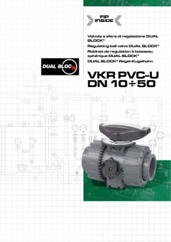
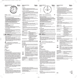
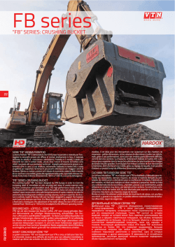
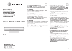
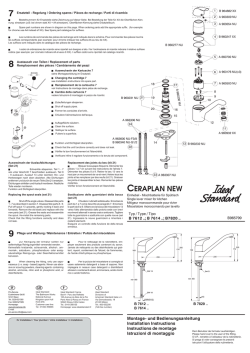
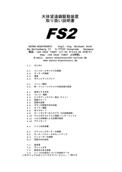
Valvola a sfera di regolazione
DUAL BLOCK®
DUAL BLOCK® regulating ball valve
Robinet de régulation DUAL BLOCK®
DUAL BLOCK® Regel-Kugelventil
VKR PVDF
DN 10÷50
VKR PVDF
DN 10÷50
I dati del presente prospetto sono forniti
in buona fede. La FIP non si assume alcuna responsabilità su quei dati non direttamente derivati da norme internazionali.
La FIP si riserva di apportarvi qualsiasi
modifica.
L’installazione e la manutenzione del prodotto deve essere eseguita da personale
qualificato.
The information in this leaflet is provided
in good faith. No liability will be accepted
concerning technical data that is not directly covered by recognised international
standards. FIP reserves the right to carry
out any modification to the products
shown in this leaflet.
Les données contenues dans cette
brochure sont fournies en toute bonne foi.
FIP n’assume aucune responsabilité pour
les données qui ne dérivent pas directement
des normes internationales. FIP se réserve
le droit d’apporter toute modification aux
produits présentés dans cette brochure.
Die in diesem Prospekt enthaltenen Daten
werden nach bestem Wissen erteilt. FIP
haftet nicht für nicht direkt aus internationalen Normen abgeleitete Daten.
FIP behält sich das Recht auf jegliche
Änderungen vor.
Products must be installed and maintained by qualified personnel.
L’installation et la manutention doivent être
effectuées par du personnel qualifié.
Installations- und Wartungsarbeiten
sind von Fachleuten vorzunehmen.
2
VKR PVDF
DN 10÷50
Valvola a sfera
di regolazione
DUAL BLOCK®
DUAL BLOCK®
regulating ball valve
Robinet de régulation
à boisseau sphérique
DUAL BLOCK®
DUAL BLOCK®
Regel-Kugelventil
La valvola FIP VKR DUAL BLOCK®
combina le elevate doti di affidabilità e sicurezza tipiche della valvola
a sfera full bore VKD con la nuova
funzione di regolazione del flusso,
precisa e ripetibile, che risponde alle più severe esigenze richieste nelle
applicazioni industriali.
FIP VKR DUAL BLOCK® valves
combine typical full bore VKD ball
valve reliability and safety along
with a new accurate, repeatable
flow regulation function which
meets the most extreme requirements of industrial applications.
Le robinet FIP VKR DUAL BLOCK®
associe les facultés de fiabilité et de
sécurité qui caractérisent le robinet
à boisseau sphérique VKD avec la
nouvelle fonction de régulation du
débit, précis et renouvelable, qui
répond aux exigences les plus sévères requises dans les applications
industrielles.
Das Ventil FIP VKR DUAL BLOCK®
kombiniert die hervorragenden,
für das Full Bore-Kugelventil VKD
typischen Eigenschaften hinsichtlich
Zuverlässigkeit und Sicherheit mit
der neuen Funktion der präzisen
und wiederholbaren Flussregelung,
die auch den anspruchsvollsten Anforderungen industrieller
Anwendungen gerecht wird.
• Design della sfera brevettato
che assicura una regolazione del
flusso lineare su tutto il campo di
funzionamento, a partire dai primi
gradi di apertura della valvola e
garantendo valori di perdita di
carico estremamente ridotti
• Angolo di funzionamento di 90°
(come una valvola a sfera per intercettazione di tipo tradizionale)
che permette l’utilizzo di attuatori
a quarto di giro di tipo standard
• Valvola adatta al convogliamento
di fluidi puliti e privi di particelle
in sospensione
• Maniglia dotata di piattello di
indicazione della posizione con
scala graduata con un dettaglio
di 5° per una lettura chiara ed
accurata
• Sistema brevettato DUAL BLOCK®
che assicura il serraggio delle
ghiere anche nel caso di condizioni di servizio gravose come, per
esempio, in presenza di vibrazioni
o dilatazioni termiche
• Sistema di tenuta SEAT-STOP,
possibilità di micro-registrazione
con apposita ghiera e sistema di
bloccaggio delle spinte assiali
• Gamma dimensionale da DN10
a DN50
• Possibilità di giunzione per saldatura nel bicchiere o di testa, per
filettatura e per flangiatura
• Resistenza a pressioni di esercizio
fino a 16 bar a 20° C
• Facile smontaggio radiale dall’impianto e conseguente rapida
sostituzione degli O-ring e delle
guarnizioni della sfera senza
l’impiego di alcun attrezzo
• Possibilità di smontaggio delle
tubazioni a valle con la valvola in
posizione di chiusura
• Opzioni: Versione con attuatore
elettrico modulante con ingresso
4-20 mA / 0-10 V e uscita 4-20
mA / 0-10 V per il monitoraggio
della posizione
Per maggiori informazioni visitare il
sito: www.fipnet.it.
• The patented ball design provides linear flow regulation
throughout its range of operation
even when the valve is open just
a few degrees and guarantees
minimum pressure losses.
• 90° operating angle (like a traditional shut-off ball valve) which
allows the use of standard quarter turn actuators
• Valve suitable for carrying fluids
that are clean and free of suspended particles
• Handle fitted with disc showing
valve position on a graduated
scale of 5° for accurate, easy
reading
• Patented DUAL BLOCK® system:
which prevents lock nuts from
slackening even under extreme
operating conditions: e.g.
vibration or thermal expansion
• SEAT-STOP seal system, option of
making micro-adjustments with
lock nuts and axial thrust blocking system.
• Size range from DN 10 to DN 50
• Option of jointing by socket fusion or butt welding for threaded
or flanged connections
• Maximum operating pressure - up
to 16 bar at 20° C
• Valve body easily removed allowing quick replacement of O-rings
and ball seats without any need
for tools
• Option of disconnecting downstream pipes with the valve in the
closed position
• Options: Version with electric
regulating valve with 4-20 mA /
0-10 V inlet and 4-20
mA / 0-10 V outlet for monitoring
the position
For further information, please visit
our website: www.fipnet.it.
• Design de la sphère breveté qui
assure une régulation linéaire
du débit sur tout le domaine de
fonctionnement, à partir des premiers degrés d’ouverture du robinet en garantissant des valeurs
de perte de charge extrêmement
réduites.
• Angle de fonctionnement de 90°
(comme un robinet à boisseau
sphérique d’interception de type
traditionnel) qui permet l’utilisation d’actionneurs quart de tour
de type standard.
• Robinet adapté au transport de
fluides propres et sans particules
en suspension.
• Poignée dotée d’une palette
d’indication de la position avec
échelle graduée avec un détail
de 5° pour une lecture claire et
soignée.
• Système breveté DUAL BLOCK®
qui assure le serrage des écrous
union, même en cas de conditions
de service difficiles telles que la
présence de vibrations ou de dilatations thermiques.
• Système d’étanchéité SEAT-STOP,
possibilité de micro-réglage avec
écrou spécifique et système de
blocage des poussées axiales.
• Gamme de dimension de DN10
à DN50.
• Possibilité de jonction pour soudure dans l’emboîture ou bout à
bout, pour filetage et pour bride.
• Résistance à des pressions de
service allant jusqu’à 16 bars à
20° C.
• Démontage radial facile de l’installation et par conséquent remplacement rapide des O-ring et
des joints de la sphère sans l’aide
d’aucun outil.
• Possibilité de démontage des
tuyaux en aval avec le robinet en
position fermée.
• Options : Version avec actionneur
électrique système modulaire avec
entrée 4-20 mA / 0-10 V et sortie
4-20 mA / 0-10 V pour le monitorage de la position.
• Patentiertes Kugel-Design, das
eine lineare Flussregelung bei
allen Betriebswerten, beginnend bei den ersten Graden der
Ventilöffnung und extrem geringe
Druckverlustwerte garantiert
• 90°-Betriebswinkel (wie ein
Absperrventil herkömmlichen Typs), der den Einsatz
von Standard-Antriebe mit
Vierteldrehung gestattet
• Für saubere und keine suspendierten Partikel enthaltende
Flüssigkeiten geeignetes Ventil
• Handgriff mit Positionsanzeige
und Skala mit 5°-Schritten für
klare und genaue Ablesungen
• Patentiertes DUAL BLOCK®System, das die Überwurfmuttern
auch bei schwersten
Einsatzbedingungen wie
Vibrationen oder thermischen
Ausdehnungen sicher in Position
hält
• SEAT-STOP-Dichtungskonzept
mit Möglichkeit der MikroJustierung durch Überwurfmutter
und Abdichtungssystem gegen
Rohrleitungskräfte.
• Größen von DN10 bis DN50
• Die Verbindung kann durch
Heizelementmuffenschweißen
oder
Heizelementstumpfschweißen
oder Gewinde- und
Flanschanschlüsse erfolgen.
• Der maximale Betriebsdruck beträgt 16 bar bei 20° C
• Der einfache radiale Ausbau der
Armatur aus dem Leitungssystem
gestattet den schnellen Wechsel
von O-Ringen oder Kugelsitzen
ohne jegliches Werkzeug
• In geschlossener Stellung des
Kugelventils kann die drucklose
Seite der Leitung ohne Leakage
gelöst werden
• Optionen: Ausführung mit elektrisch modulierendem Stellantrieb
mit Eingang 4-20 mA / 0-10 V
und Ausgang 4-20
mA / 0-10 V zur Positionskontrolle
Pour plus d’informations, visiter le
site : www.fipnet.it.
Für weitere Details besuchen Sie
unsere Website: www.fipnet.it.
3
VKR PVDF
DN 10÷50
Legenda
d
diametro nominale
esterno del tubo in mm
d
nominal outside diameter of the pipe in mm
d
diamètre extérieur
nominal du tube en mm
d
Rohraußendurchmesser
in mm
DN diametro nominale
interno in mm
DN nominal internal
diameter in mm
DN
diamètre intérieur
nominal du tube en mm
DN Rohrnennweite in mm
pressione nominale in
bar (pressione max di
esercizio a 20°C in
acqua)
PN nominal pressure in bar
(max. operating pressure
at 20°C - water)
PN
pression nominale en
bar (pression de service
maximale à 20° C eau)
PN Nenndruck in bar (max.
zulässiger Betriebsdruck
bei 20° C in Wasser)
g
peso in grammi
g
weight in grams
g
poids en grammes
g
Gewicht in Gramm
U
numero dei fori
U
number of holes
U
nombre de trous
U
Anzahl der
Schraubenlöcher
SDR standard dimension
ratio = d/s
SDR standard dimension
ratio = d/s
SDR
dimension standard
ratio = d/s
SDR Standardgröße
Ratio = d/s
PVDF polifluoruro di vinilidene
PVDF polyvinylidene fluoride
PVDF
polyfluorure de vinylidène
PVDF Polyvinylidenfluorid
HIPVC
PVC alto impatto
HIPVC
high impact PVC
HIPVCPVC haut impact
HIPVC
schlagfestes PVC
PN FPM (FKM) fluoroelastomero
FPM (FKM) vinylidene fluoride
rubber
FPM (FKM) fluorélastomère de
vinylidène
FPM (FKM) Fluorelastomer
PTFE politetrafluoroetilene
PTFE polytetrafluoroethylene
PTFE
polytétrafluoroéthylène
PTFE Polytetraflourethylen
PE polietilene
PE polyethylene
PE
polyéthylène
PE Polyethylen
POM resina poliacetalica
POM polyoxymethylene
POM
résine de polyacétal
POM Polyoxymethylen
PP-GR
polipropilene rinforzato
fibre di vetro
PP-GRpolypropylene
reinforced fibreglass
PP-GR
polypropylène renforcé
fibre de verre
PP-GR
4
Polypropilen glasfaserverstärkt
Glasfaser
VKR PVDF
DN 10÷50
1
Technical
Data
20
3/8
32
25
1/2
3/4
1
40
11/4
50
11/2
1
63 d
2
R
Technische
Daten
10
100
1000
10000 l/min
bar
perdita di carico - pressure lost - perte de charge - Druckverlust
momento di manovra - torque - couple
de manoeuvre - Betätigungsmomente
16
Nm
20
18
16
14
12
10
8
6
4
2
0
Données
Techniques
2
DN
DN 10
DN 15
20
DN
25
DN
DN 32
40
DN
50
Dati
Tecnici
1
0,1
0,01
0,001
portata - flow rate- débit - Durchflussmenge
3
-40 -20
0
20
40
60
80 100 120 140 °C
5 10 15 20 25 30 35 40 45 50 55 60 65 70 75 80 85 90 °
%
coefficiente di flusso kv100 - flow coefficient kv100 coefficient de débit kv100 - kv100 Wert
pressione di esercizio - working pressure
pression de service - Betriebsdruck
bar
16
14
12
10
8
6
4
2
0
100
90
80
70
60
50
40
30
20
10
0
temperatura di esercizio - operating temperature
température de service - Betriebstemperatur
angolo di apertura - relative valve travel
angle d’ouverture - Öffnungswinkel
5
DN
kV100
10
83
15
88
20
135
25
256
32
478
40
592
50
1068
1 Coppia di manovra alla massima
Max torque at maximum operating
pressure
Couple de manœuvre à la pression
maximale de service
Betätigungsmomente bei höchstem
Betriebsdruck
2 Diagramma delle perdite di carico
Pressure loss chart
Diagramme des pertes de charge
Druckverlust-Diagramm
3 Variazione della pressione in fun-
Pressure/temperature variations in
relation to the temperature of water
and harmless fluids to which the
material is CHEMICALLY RESISTANT.
In other cases, a reduction of the
nominal PN is required. (25 years
with safety factor)
Variation de la pression en fonction de
la température pour l’eau et les fluides
non agressifs pour lequel le matériau est considéré CHIMIQUEMENT
RÉSISTANT. Pour les autres cas une
diminution de la pression nominale PN
est nécessaire. (25 années avec facteur
de sécurité inclus)
Temperaturabhängige Druckänderung
für Wasser und ungefährliche
Medien gegen die das Material
als CHEMISCH BESTÄNDIG
eingestuft ist. In allen anderen
Fällen ist eine entsprechende
Reduzierung der Druckstufe erforderlich. (Unter Berücksichtigung des
Sicherheitsfaktors für 25 Jahre)
4 Diagramma del coefficiente di flusso
Relative flow chart. Valve opening
angle (°)/ kv100 (%)
Diagramme du coefficient de débit
relatif. Angle d’ouverture (°)/ kv100
Diagramm des relativen
Durchflusskoeffizienten.
Öffnungswinkel (°)/ kv100
5 Coefficiente di flusso kv100*
Flow coefficient kv100*
Coefficient de débit kv100*
Durchflusskoeffizient kv100*
*kv100 is the number of litres per minute of
*Pour coefficient de débit kv100 est le débit Q
*Der kv100 - Wert nennt den Durchsatz in
I/min für Wasser bei 20° C und einem ∆p
von 1 bar bei völlig geöffnetem Ventil.
Die in der Tabelle angegebenen Kv100-Werte
beziehen sich auf die vollkommen geöffnete
Armatur.
pressione di esercizio
zione della temperatura per acqua
o fluidi non pericolosi nei confronti
dei quali il materiale è classificato
CHIMICAMENTE RESISTENTE. In altri
casi è richiesta un’adeguata diminuzione della pressione nominale PN.
(25 anni con fattore di sicurezza)
relativo. Angolo di apertura (°)/ kv100
*Per coefficiente di flusso kv100 si intende la
portata Q in litri al minuto di acqua a 20°C che
genera una perdita di carico ∆p= 1 bar per una
determinata posizione della valvola.
I valori kv100 indicati in tabella si intendono per
valvola completamente aperta.
water at a temperature of 20°C that will flow
through the valve with Δp= 1 bar
The kv100 values shown in the table are calculated with the valve completely open.
en litres par minute d’eau, à une température
de 20°C, qui génère une perte de charge ∆p=
1 bar pour une position déterminée du robinet.
Les valeurs kv100 indiquées sur le tableau sont
évaluées lorsque le robinet est entièrement
ouvert.
5
4
VKR PVDF
DN 10÷50
Dimensioni
Dimensions
Dimensions
Größen
La FIP ha approntato una gamma di
valvole a sfera, i cui attacchi sono in
accordo con le seguenti norme:
Saldatura termica nel bicchiere:
ISO 10931, DVS 2207-15
Da accoppiare con tubi secondo
ISO 10931.
Flangiatura: ISO 10931, DIN 2501,
ISO 7005-1, EN 1092-1,
ANSI B16.5 cl.150.
FIP have produced a complete range
of ball valves whose couplings comply with the following standards:
Socket fusion: ISO 10931, DVS 2207-15
For coupling to pipes complying with:
ISO 10931.
Flanged couplings: ISO 10931,
DIN 2501, ISO 7005-1, EN 1092-1,
ANSI B16.5 cl.150.
FIP a réalisé une gamme complète
de robinets à tournant sphérique
dont les embouts sont conformes aux
normes suivantes :
Soudure dans l’emboîture :
ISO 10931, DVS 2207-15
À assembler à des tubes conformes
aux normes : ISO 10931.
Brides : ISO 10931, DIN 2501,
ISO 7005-1, EN 1092-1,
ANSI B 16.5 150 cl.
Die Anschlüsse der von FIP angebotenen Kugelhahnreihe entsprechen den
folgenden
Normen:
Schweißanschluss: ISO 10931,
DVS 2207-15
Für Verbindungen mit Rohren nach
ISO 10931.
Flanschanschluss: ISO 10931,
DIN 2501, ISO 7005-1, EN 1092-1,
ANSI B16.5 cl.150.
VKRIF
Valvola a sfera di regolazione DUAL
BLOCK® con attacchi femmina per
saldatura nel bicchiere PVDF, serie
metrica
DUAL BLOCK® regulating ball valve
with metric series female ends for
PVDF socket fusion welding
DUAL BLOCK®-Regel-Kugelhahn
mit Schweißmuffen für
Heizelementmuffenschweißen
Robinet de régulation à boisseau
sphérique DUAL BLOCK® avec
embouts femelles pour soudure dans
l’emboîture PVDF, série métrique
d
DN
PN
L
Z
H
H1
E
B
B1
C
C1
g
16
20
25
32
40
50
63
10
15
20
25
32
40
50
16
16
16
16
16
16
16
14
14,5
16
18
20,5
23,5
27,5
74,5
73
82
90
100
117
144
102
102
114
126
141
164
199
65
65
70
78
88
93
111
54
54
65
73
86
98
122
54
54
65
69,5
82,5
89
108
29
29
34,5
39
46
52
62
67
67
85
85
108
108
134
40
40
49
49
64
64
76
291
272
445
584
938
1242
2187
VKRDF
Valvola a sfera di regolazione DUAL
BLOCK® con attacchi maschio per
incollaggio, serie metrica
DUAL BLOCK Regulating Ball Valve
with metric series male ends for
solvent welding
DUAL BLOCK®-Regel-Kugelhahn mit
Robinet de régulation à boisseau
Klebemuffe, metrische Serie
sphérique DUAL BLOCK® avec
embouts mâle à coller, série métrique ®
d
DN
PN
L
H
H1
E
B
B1
C
C1
g
20
25
32
40
50
63
15
20
25
32
40
50
16
16
16
16
16
16
16
18
20
22
23
29
124
144
154
174
194
224
65
70
78
88
93
111
54
65
73
86
98
122
54
65
69,5
82,5
89
108
29
34,5
39
46
52
62
67
85
85
108
108
134
40
49
49
64
64
76
299
466
604
951
1284
2229
VKROF
Valvola a sfera di regolazione DUAL
DUAL BLOCK Regulating Ball Valve
BLOCK® con flange fisse EN/ISO/DIN
with fixed flanges EN/ISO/DIN PN
PN 10/16, scartamento secondo EN
10/16, face to face dimensions as
558-1
per EN 558-1
®
Robinet de régulation à boisseau
sphérique DUAL BLOCK® avec
brides fixes EN/ISO/DIN PN10/16.
Longueur hors-tout EN 558-1
DUAL BLOCK®-Regel-Kugelhahn mit
Festflanschen EN/ISO/DIN PN 10/16
Baulänge nach EN 558-1
d
DN
PN
H
H1
B
B1
C
C1
F
f
U
Sp
g
20
25
32
40
50
63
15
20
25
32
40
50
16
16
16
16
16
16
130
150
160
180
200
230
65
70
78
88
93
111
54
65
69,5
82,5
89
108
29
34,5
39
46
52
62
67
85
85
108
108
134
40
49
49
64
64
76
65
75
85
100
110
125
14
14
14
18
18
18
4
4
4
4
4
4
11
14
14
14
16
16
547
772
1024
1583
2024
3219
6
VKR PVDF
DN 10÷50
VKROAF
Valvola a sfera di regolazione DUAL
BLOCK® con flange fisse foratura
ANSI B16.5 cl.150#FF
DUAL BLOCK Regulating Ball Valve
with ANSI B16.5 cl.150#FF fixed
flanges
®
DUAL BLOCK®-Regel-Kugelhahn
mit Festflanschen nach ANSI B16.5
cl.150#FF
Robinet de régulation à boisseau
sphérique DUAL BLOCK® avec brides
fixes ANSI B 16.5 150 CL. # FF
d
DN
PN
H
H1
B
B1
C
C1
F
f
U
Sp
g
1/2”
3/4”
1”
1 1/4”
1 1/2”
2”
15
20
25
32
40
50
16
16
16
16
16
16
143
172
187
190
212
234
65
70
78
88
93
111
54
65
69,5
82,5
89
108
29
34,5
39
46
52
62
67
85
85
108
108
134
40
49
49
64
64
76
60,3
69,9
79,4
88,9
98,4
120,7
15,9
15,9
15,9
15,9
15,9
19,1
4
4
4
4
4
4
11
14
14
14
16
16
547
772
1024
1583
2024
3219
VKRBF
Valvola a sfera di regolazione DUAL
BLOCK® con attacchi maschio in
PVDF a codolo lungo per saldatura
testa a testa/IR (CVDF)
DUAL BLOCK® regulating ball valve
with long spigot male ends in PVDF
for head to head IR (CVDF) fusion
welding
DUAL BLOCK®-Regel-Kugelhahn mit
langem Schweißstutzen aus PVDF
für Stumpfschweißen/IR (CVDF)
Robinet de régulation à boisseau
sphérique DUAL BLOCK® avec embouts mâles en PVDF pour soudure
bout-à-bout/IR (CVDF)
d
DN
PN
L
Z
H
H1
E
B
B1
C
C1
g
20
25
32
40
50
63
15
20
25
32
40
50
16
16
16
16
16
16
41
52
55
56
58
66
89
100
110
126
138
154
171
204
220
238
254
286
65
70
78
88
93
111
54
65
73
86
98
122
54
65
70
83
89
108
29
35
39
46
52
62
67
85
85
108
108
134
40
49
49
64
64
76
450
516
664
1020
1350
2330
7
VKR PVDF
DN 10÷50
Accessori
Accessories
Accessoires
Zubehör
CVDF (VKRBF)
CONNETTORI IN PVDF
CODOLO LUNGO
per saldatura testa a testa/IR
PVDF LONG SPIGOT
END CONNECTORS
for butt fusion/IR
EMBOUTS EN PVDF
POUR SOUDURE
bout à bout/IR
PVDF ANSCHLUSSTEILE MIT
LANGEM STUTZEN
für Stumpfschweißen/IR
d
DN
PN
L
H
SDR
Codice/Part number
Code/Artikelnummer
20
25
32
40
50
63
15
20
25
32
40
50
16
16
16
16
16
16
53
67
71
75
80,5
87,5
171
204
220
238
254
286
13,6
13,6
13,6
17
17
21
CVDF21020
CVDF21025
CVDF21032
CVDF21040
CVDF21050
CVDF21063
PMKD
Piastrina di montaggio a muro
Mounting plate
Platine de montage
Wandmontageplatte
d
DN
A
B
C
C1
C2
F
f
f1
S
Codice/Part number
Code/Artikelnummer
16
20
25
32
40
50
63
10
15
20
25
32
40
50
30
30
30
30
40
40
40
86
86
86
86
122
122
122
20
20
20
20
30
30
30
46
46
46
46
72
72
72
67,5
67,5
67,5
67,5
102
102
102
6,5
6,5
6,5
6,5
6,5
6,5
6,5
5,3
5,3
5,3
5,3
6,3
6,3
6,3
5,5
5,5
5,5
5,5
6,5
6,5
6,5
5
5
5
5
6
6
6
PMKD1
PMKD1
PMKD1
PMKD1
PMKD2
PMKD2
PMKD2
8
VKR PVDF
DN 10÷50
Staffaggio e
supportazione
Brackets and
supports
Fixation et
support
Kugelhahn-Halterung
und -Befestigung
Tutte le valvole, sia manuali che
motorizzate, necessitano in molte
applicazioni di essere supportate
mediante staffe o supporti al fine
di proteggere tratti di tubazione
ad esse collegati dall’azione di
carichi concentrati.
Questi supporti devono essere
in grado di resistere sia al peso
proprio della valvola, sia alle sollecitazioni generate dalla valvola
stessa durante le fasi di apertura
e chiusura.
La serie di valvole VKR è dotata di
supporti integrati che permettono
un ancoraggio diretto sul corpo
valvola senza bisogno di ulteriori
componenti.
Si ricorda che, vincolando la
valvola, essa viene ad agire come
punto fisso di ancoraggio, per
cui viene ad essere sottoposta ai
carichi terminali delle tubazioni.
Specialmente ove siano previsti
ripetuti cicli termici, occorrerà prevedere di scaricare la dilatazione
termica su altre parti dell’impianto
in modo da evitare pericolosi
sovraccarichi sui componenti della
valvola.
Per le installazioni a muro o a pannello è possibile utilizzare la apposita piastrina di fissaggio PMKD, fornita come accessorio, che va fissata
precedentemente alla valvola.
La piastrina PMKD serve anche per
allineare la valvola VKR con i fermatubi FIP tipo ZIKM e per allineare
valvole di misure diverse.
In many applications, all manual or
actuated valves must be supported
by simple brackets or supports to
protect sections of pipework connected with them from concentrated loads.
These supports must be capable of
withstanding weights as well as the
stresses transmitted through the
valve body during valve opening
and closing operations.
All VKR valves are therefore provided
with an integrated support on the
valve body for simple and quick
fastening with no need for other
components.
Note that when the valve is fixed
in position, it acts as an anchoring
point and is therefore subjected to
loads at the pipe ends.
Where repeated heat cycles are involved, thermal expansion must
be allowed for to prevent the
dangerous overloading of valve
components.
For wall installation, dedicated
PMKD mounting plates which are
available as accessories can be
used. These plates are to be fastened in place before the valve.
PMKD plates also allow alignment
with FIP ZIKM pipe clips as well as
allowing different sizes of valves to
be aligned.
Tous les robinets, manuels ou
propulsés, doivent être maintenus
au moyen d’étriers ou de supports
afin de protéger les tuyauteries
auxquelles ils sont raccordés contre
l’action de charges concentrées.
Ces supports doivent être en mesure de résister aussi bien au poids
du robinet qu’aux sollicitations
engendrées par le robinet lui-même
durant les phases d’ouverture ou de
de fermeture.
Toutes les vannes VKR sont équipées d’un système de fixation intégré qui permet un ancrage direct
sur le corps de la vanne sans devoir
recourir à d’autres composants.
Il faut noter qu’avec l’utilisation de
ces supports, le robinet agit comme
point fixe d’ancrage, raison pour
laquelle il peut être soumis aux
charges terminales des tubes.
Particulièrement lorsque que l’on se
trouve en présence de cycles thermiques répétés, il faut prévoir de
décharger la dilatation thermique
sur d’autres parties de l’installation,
de façon à éviter des surcharges
dangereuses sur les composants du
robinet.
Pour les installations murales ou à
panneau il est possible d’employer
la platine de montage PMKD prévue à cet effet, fournie comme accessoire, qui doit être tout d’abord
fixée à la vanne.
La platine PMKD permet aussi d’aligner la vanne VKR avec les colliers
des tubes FIP de type ZIKM ainsi
que d’aligner des vannes de dimensions différentes.
Alle manuellen wie motorbetriebenen Kugelhähne erfordern in vielen
Anwendungen die Anbringung
durch Halterungen oder
Befestigungen, um die damit verbundenen Rohrleitungsabschnitte
vor der Wirkung konzentrierter
Lasten zu schützen.
Diese Halterungen müssen
in der Lage sein, sowohl dem
Eigengewicht des Ventils als auch
den Beanspruchungen durch das
Ventil selbst beim Öffnen und
Schließen standzuhalten.
Die Ventilreihe VKR ist mit
integrierten Halterungen ausgestattet, die eine direkte Verankerung auf
dem Ventilkörper ohne weitere
Komponenten gestatten.
Es ist zu beachten, dass sich
das Ventil durch Befestigen wie
ein fester Verankerungspunkt verhält,
wodurch es den Endlasten der
Rohrleitungen ausgesetzt ist.
Insbesondere dort, wo wiederholte
Wärmezyklen vorgesehen sind,
muss dafür gesorgt werden, die
Wärmeausdehnung auf andere
Anlagenteile abzuleiten,
um gefährliche Lasten auf den
Ventilkomponenten
zu vermeiden.
Für Installationen an der Wand oder
an Platten kann die entsprechende
PMKD-Montageplatte, die
als Zubehör erhältlich ist, verwendet
werden, die zuvor am Ventil anzubringen ist.
Die PMKD Platte dient auch der
Fluchtung des VKR-Kugelventils mit
den FIP-Rohrklemmen ZIKM und
der Fluchtung von Ventilen anderer
Größen.
* Con boccole di staffaggio
d
DN
B
H
L
*J
16
20
25
32
40
50
63
10
15
20
25
32
40
50
31,5
31,5
40
40
50
50
60
27
27
30
30
35
35
40
20
20
20
20
30
30
30
M4 x 6
M4 x 6
M4 x 6
M4 x 6
M6 x 10
M6 x 10
M6 x 10
* With Bracketing bushes
* Avec écrous d’ancrage
9
* Mit Gewindebuchsen
VKR PVDF
DN 10÷50
Installazione
sull’impianto
Connection to the
system
Montage sur
l’installation
Einbau in einer
Leitung
Prima di procedere all’installazione
seguire attentamente le istruzioni di
montaggio:
1) Verificare che le tubazioni a cui
deve essere collegata la valvola
siano allineate in modo da evitare sforzi meccanici sulle connessioni filettate della stessa.
2) Svitare le ghiere (13) e inserirle
sui tratti di tubo.
3) Procedere all’incollaggio o
saldatura o avvitamento dei
manicotti (12) sui tratti di tubo.
4) Verificare che sul corpo
valvola sia installato il
sistema di blocco ghiere
DUAL BLOCK® (16). (Fig. 1).
DUAL BLOCK® è il sistema
brevettato sviluppato da
FIP che dà la possibilità di
bloccare, in una posizione
prefissata le ghiere delle
valvole a sfera a smontaggio radiale.
Il sistema di blocco assicura il serraggio delle ghiere
anche nel caso di condizioni di servizio gravose come,
per esempio, in presenza
di vibrazioni o dilatazioni
termiche.
Before proceeding with installation.
please follow these instructions
carefully:
1) Check that the pipes to be connected to the valve are aligned
in order to avoid mechanical
stress on the threaded joints
2) Unscrew the lock nuts (13)
and slide them onto the pipe.
3) Solvent/heat weld or screw the
valve end connectors (12) onto
the pipe ends.
4) Check that the DUAL
BLOCK® dedicated lock nut
device (16) is fitted to the
valve body. (Fig. 1).
DUAL BLOCK® is the patented system developed
by FIP that allows the lock
nuts of union ball valves to
be locked in a preset position for radial assembly.
The locking device ensures
that the nuts are held
in position even under
extreme operating conditions: e.g. vibration or
thermal expansion.
Avant d’effectuer le montage sur
l’installation nous vous prions de
suivre les instructions suivantes :
1) Vérifier l’alignement des tubes
pour ne pas charger sur la
vanne des efforts mécaniques
et endommager les raccordements taraudés.
2) Dévisser les écrous-unions (13)
et les insérer
sur les tubes.
3) Procéder au collage/fusion ou
visser les collets (12) de raccordement sur les tubes.
4) Installer sur la vanne le
composant de blocage (16)
que vous trouverez dans
l’emballage DUAL BLOCK®
(16). (Fig. 1).
DUAL BLOCK® est le système breveté développé
par FIP qui offre la possibilité de bloquer, dans
une position préfixée, les
écrous union des robinets à
tournant sphérique.
Le système de blocage
assure aussi la conservation de la position des
écrous union, même en cas
de conditions de service
difficiles : par exemple en
cas de vibrations ou de
dilatations thermiques.
Vor der Installation unbedingt alle
Anweisungen beachten:
1) Prüfen Sie, ob die mit dem
Ventil zu verbindenden Rohre
so gefluchtet sind, dass mechanische Beanspruchungen
auf den Gewindeverbindungen
derselben vermieden werden.
2) Lösen Sie die Überwurfmuttern
(13) und schieben Sie sie
auf die Rohrabschnitte.
3) Kleben, schweißen oder schrauben Sie die Anschlußteile (12)
auf die Rohrenden.
4) Überprüfen Sie, ob
die Sperrvorrichtung
der Überwurfmutter
DUAL BLOCK® (16) am
Ventilgehäuse montiert ist.
(Abb. 1).
DUAL BLOCK® ist das von
FIP entwickelte patentierte
System, das es ermöglicht,
die Überwurfmuttern der
Kugelventile in einer festgelegten Stellung zu arretieren.
Die Sperrvorrichtung sichert die Überwurfmuttern
auch unter stark
beanspruchenden
Einsatzbedingungen wie
Vibrationen oder thermischer Ausdehnung.
Fig. 1
10
VKR PVDF
DN 10÷50
5) Posizionare la valvola fra i
manicotti prestando attenzione
a rispettare il senso del flusso
indicato sulla piastrina (Fig.2).
Procedere serrando completamente le ghiere a mano in senso orario senza utilizzare chiavi
o altri utensili che possano
danneggiarne la superficie. Per
sbloccare le ghiere basta agire
con un dito sull’apposita leva
di sblocco premendola assialmente per allontanare il blocco
dalla ghiera, e poi svitare in
senso anti-orario la stessa.
6) Se richiesto supportare la tubazione per mezzo dei fermatubi
FIP o per mezzo del supporto
integrato nella valvola (vedi il
paragrafo “staffaggio e supportazione”).
5) Position the valve between the
pipe end connectors making
sure the that direction of flow is
the same as shown on the plate
(Fig.2). Hand tighten the lock
nuts in the clockwise direction.
Do not use a wrench or other
tools which might damage the
surface. To release the lock nuts,
simply apply finger pressure to
the release lever and press along
the axis to separate the ring then
unscrew the ring itself in the
anti-clockwise direction.
6) If necessary, support the pipework with FIP pipe clips or by
means of the valve itself (see
“brackets and supports”).
5) lnsérez le robinet entre les deux
collets et serrez bien les écrous
dans le sens horaire (Fig.3) en
utilisant les mains pour ne pas
endommager la surface des
écrous union. Ainsi les écrous
union sont bloquées; pour les
débloquer il faut tout simplement appuyer un doigt sur le
petit levier et lui déplacer du
filetage de l’écrous union.
6) lorsqu’il soit nécessaire supporter la vanne par mis des pipe
clips FIP ou bien du support
intégré dans la vanne même,
on recommande de voir la partie “fixation et supporte”.
5) Positionieren Sie das
Ventil zwischen den beiden
Anschlussteilen und achten Sie
dabei auf die Einhaltung der
auf der Platte angegebenen
Flussrichtung (Abb. 2). Dann
die Überwurfmuttern von Hand
im Uhrzeigersinn fest anziehen,
ohne Schlüssel oder andere
Werkzeuge zu verwenden, die ihre Oberfläche beschädigen können. Um die Überwurfmuttern
zu lösen, genügt es, mit einem
Finger den entsprechenden
Freigabehebel zu betätigen,
indem dieser axial gedrückt wird,
um die Überwurfmutter freizugeben und diese dann gegen den
Uhrzeigersinn aufzuschrauben.
6) Befestigen Sie die Rohrleitung
wenn nötig mit FIPRohrhalterungen oder mit Hilfe
der am Ventilboden integrierten
Anbringung (siehe auch den
Abschnitt „Halterung und
Befestigung“).
Fig. 2
Smontaggio
Disassembly
Démontage
Demontage
1) Isolare la valvola dalla linea (togliere la pressione e svuotare
la tubazione).
2) Sbloccare le ghiere premendo sulla leva del DUAL
BLOCK® (16) in direzione
assiale allontanandola dalla ghiera.
Vedi punto 5 “Installazione
sull’Impianto”.
é comunque possibile
rimuovere completamente
il dispositivo di blocco dal
corpo valvola.
3) Svitare completamente le ghiere (13) e sfilare lateralmente la
valvola.
4) Prima di smontare la valvola
occorre drenare eventuali residui di liquido rimasti all’interno
aprendo a 45° la valvola in
posizione verticale.
1) Isolate the valve from the line
(release the pressure and empty
the pipeline).
2) Unlock the lock nuts by
pressing the lever on
the DUAL BLOCK® (16)
along the axis to separate
the ring.
See point 5 of “Connection
to the system”.
It is also possible
to completely remove the
block device from the body
of the valve.
3) Unscrew the lock nuts (13) and
extract the valve.
4) Before dismantling, hold the
valve in a vertical position and
open it 45° to drain any liquid
that might remain.
1) Isoler la vanne de la ligne
(décharger la pression et
vider les tubes).
2) Débloquer les écrous union
en appuyant sur le levier
du DUAL BLOCK® (16) dans
la direction de l’axe tout
en l’éloignant de l’écrou.
Voir point 5 “montage sur
l’installation”.
il est aussi possible
de retirer complètement
le dispositif de blocage du
corps de la vanne.
3) Dévisser complètement les
écrous (13) et retirer latéralement la vanne.
4) Avant de démonter la vanne il
faut drainer d’éventuels résidus
de liquide restés à l’intérieur
en ouvrant à 45° la vanne en
position verticale.
1) Das Ventil von der Leitung isolieren (Druck ablassen und Leitung
entleeren).
2) Entsperren Sie die
Überwurfmuttern durch
Drücken auf den Hebel
des DUAL BLOCK® (16) in
axialer Richtung von der
Überwurfmutter weg.
Siehe Punkt 5 “Installation
auf der Anlage”
Es ist in jedem Fall möglich,
die Sperrvorrichtung
vollkommen aus dem
Kugelventilgehäuse zu entfernen.
3) Nach dem Lösen beider
Überwurfmuttern (13) kann das
Kugelventil seitlich herausgezogen werden.
4) Vor der Demontage des Ventiles
halten Sie es senkrecht und öffnen Sie es 45°, um verbliebene
Flüssigkeit ablaufen zu lassen.
11
VKR PVDF
DN 10÷50
5) Dopo aver portato la valvola in
posizione di chiusura, estrarre
dalla maniglia (2) l’apposito
inserto (1) ed introdurre le due
sporgenze nelle corrispondenti
aperture dell’anello di fermo (11),
estraendolo con una rotazione
antioraria.
6) Tirare la maniglia (2) verso l’alto
per estrarla dall’asta comando (4).
7) Assicurarsi che l’indicatore di posizione (29) rimanga correttamente
ancorato alla maniglia (2).
8) Premere sulla sfera (6) da lato
opposto alle scritte “REGOLARE
- ADJUST”, avendo cura di non
rigarla, fino ad ottenerne la fuoriuscita dalla cassa.
9) Premere sull’asta comando (4)
verso l’interno fino ad ottenerne la fuoriuscita dalla cassa.
10) Ovviamente tutti gli O-ring (3,
8, 9, 10) e i seggi in PTFE (5)
vanno estratti dalle loro sedi,
come da esploso.
5) After closing the valve, remove
the special insert (1) from the
handle (2) and push the two
projecting ends into the corresponding recesses on the ball
seat stop ring (11).
Rotate the stop ring anti-clockwise.
6) Pull the handle (2) upwards to
remove it from the valve stem (4)
7) Make sure that the position
indicator (29) remains properly
fastened to the handle (2).
8) Push the ball (6) from the other
side of the words “REGOLARE
- ADJUST” taking care not to
score it, until the seat support
(11) drops out.
9) Press the stem (4) to drop
through into the valve body.
10) All the O-rings (3, 8, 9, 10)
and PTFE seats (5) must be
removed from their grooves, as
shown in the exploded view.
5) Après avoir mis le robinet en
position de fermeture, enlever
de la poignée (2) l’outil (1) et
introduire les deux saillies dans
les ouvertures correspondantes
de la bague de fermeture (11),
en la retirant par une rotation
dans le sens inverse des
aiguilles d’une montre.
6) Tirer la poignée (2) vers le haut
pour l’extraire de la tige de
manœuvre (4).
7) S’assurer que l’indicateur de
position (29) reste correctement
ancré à la poignée (2).
8) Exercer une pression sur la
sphère (6) du côté opposé
à l’inscription “REGOLARE ADJUST”, en prenant soin de
ne pas la rayer jusqu’à ce que
le support de la garniture sorte.
9) Exercer une pression sur la tige
de manœuvre (4) vers
l’intérieur pour la faire sortir.
10)Tous les O-rings (3, 8, 9, 10) et
les garnitures de la sphère de
PTFE (5) doivent naturellement
être enlevés de leurs logements
(voir la vue éclatée).
5) Nachdem das Ventil in die
geschlossene Position gebracht
wurde, den entsprechenden
Einsatz (1) aus dem Handgriff
(2) ziehen und die beiden
hervorstehenden Teile in die
Öffnungen des Halterings (11)
einsetzen, um diesen gegen den
Uhrzeigersinn herauszudrehen.
6) Den Handgriff (2) nach oben
ziehen, um ihn aus der Spindel
(4) herauszuziehen.
7) Vergewissern Sie sich, dass die
Positionsanzeige (29) korrekt
auf dem Handgriff (2) verankert
bleibt.
8) Drücken Sie von der der
Aufschrift “REGOLARE ADJUST” gegenüberliegenden
Seite auf die Kugel (6) und achten Sie dabei darauf, diese nicht
zu zerkratzen, bis diese aus dem
Gehäuse austritt.
9) Nach innen auf die Spindel (4)
drücken, damit diese aus dem
Gehäuse austritt.
10) Natürlich sind alle O-Ringe (3, 8,
9, 10) und PTFE Kugelsitze (5)
wie in der Explosionszeichnung
dargestellt aus ihren Nuten zu
entfernen.
Montaggio
Assembly
Montage
Montage
1) Tutti gli O-ring (3, 8, 9, 10)
vanno inseriti nelle loro sedi,
come da esploso.
2) Inserire l’asta comando (4)
dall’interno della cassa (7).
3) Inserire le guarnizioni in PTFE
(5) nella sedi della cassa (7) e
del supporto (11).
4) Inserire la sfera (6) nella cassa
orientandola come rappresentato in Fig. 3.
5) Inserire nella cassa il supporto
solidale all’anello di fermo
(11) e avvitare in senso orario
servendosi dell’apposito inserto
(1) fino a battuta.
6) Posizionare l’indicatore (29)
sulla maniglia orientando il
puntatore al valore 0 della
scala graduata assicurandosi di
mantenere la valvola in posizione di chiusura.
7) Inserire la maniglia (2) con l’inserto (1) sull’asta comando (4).
8) Inserire la valvola tra i manicotti (12) verificando il senso del
flusso indicato sulla piastrina
(Fig.2), quindi serrare le ghiere
(13) avendo cura che gli O-ring
di tenuta di testa (10) non fuoriescano dalle sedi.
1) All the O-rings (3, 8, 9, 10)
must be inserted in their
grooves as shown in the exploded view.
2) Insert the stem (4) from inside
the valve body (7).
3) Place the PTFE seats (5) in the
housings in the valve body (7)
and in the support (11).
lnsert the ball (6) in the valve
body as shown in Fig. 3
5) Screw the support (11) into the
body and tighten up in the
clockwise direction using the
special insert (1) housed in the
handle (5).
6) Position the indicator (29) on
the handle with the pointer set
to 0 on the graduated scale
while making sure that the
valve is in the closed position.
7) Insert the handle (2) with the
insert (1) in its housing on the
stem (4).
8) lnsert the end connectors (12)
making sure that they match
the direction of flow shown on
the plate (Fig. 2) then tighten
the lock nuts (13) making sure
that the socket O-rings(10) do
not come out of their grooves.
1) Tous les O-rings (3, 8, 9, 10)
doivent naturellement être
insérés dans leur logement (voir
vue éclatée).
2) Insérer la tige de manœuvre (4)
en passant par l’intérieur (7).
3) Insérer les garnitures en PTFE
(5) dans le siège du corps (7) et
dans la siège du support (11).
4) Insérer la sphère (6) dans le
corps en l’orientant comme
indiqué en Fig. 3.
5) Insérer à l’intérieur le support
solidaire de la bague d’arrêt
(11) et visser dans le sens
des aiguilles d’une montre en
utilisant l’outil approprié (1)
jusqu’à la butée.
6) Placer l’indicateur (29) sur la
poignée en orientant le pointeur sur la valeur 0 de l’échelle
graduée en s’assurant de
maintenir la vanne en position
fermée.
7) Positionner la poignée (2) avec
la bague (1) sur la tige (4).
8) Insérer la vanne entre les
collets (12) en vérifiant le
sens du débit indiqué sur la
plaque (Fig.2), puis serrer les
écrous (13) en ayant soin que
les joints des collets (10) ne
sortent pas de leur logement.
1) Alle in der Explosionszeichnung
dargestellten O-Ringe (3, 8, 9,
10) müssen bei der Montage
in die entsprechenden Nuten
einlegt werden.
2) Die Spindel (4) von der
Innenseite des Gehäuses (7)
einsetzen.
3) Die PTFE-Dichtungen (5) in die
Nuten des Ventilgehäuses (7)
und des Dichtungsträgers einsetzen.
4) Die Kugel (6) in das Gehäuse
einsetzen und ausrichten wie in
Abb. 3.
5) In das Gehäuse den mit
dem Haltering verbundenen
Dichtungsträger (11) einsetzen
und unter Zuhilfenahme des
Schlüsseleinsatzes bis zum
Anschlag einschrauben.
6) Die Anzeige (29) auf den
Handgriff positionieren und
dem Zeiger auf den Wert 0
der Skala stellen. Vergewissern
Sie sich dabei, das Ventil in
Schließposition zu halten.
7) Den Handgriff (2) mit dem
Schlüsseleinsatz (1) auf die
Spindel (4) drücken.
8) Das Ventil zwischen die
Anschlussteile (12) setzen und
dazu die auf der Platte (Abb.
2) angegebene Flussrichtung
kontrollieren, dann die
Überwurfmuttern (13) anziehen
und dabei darauf achten, dass
die O-Ringe (10) in den Nuten
bleiben.
12
VKR PVDF
DN 10÷50
Fig. 3
Nota
é consigliabile nelle operazioni di
montaggio, lubrificare le guarnizioni
in gomma. A tale proposito si ricorda la non idoneità all’uso degli oli
minerali, che sono aggressivi per la
gomma EPDM.
Note
During assembly operations, it is
advisable to lubricate the rubber
seals. Mineral oils are not recommended for this task as they react
aggressively with EPDM rubber.
Note
Avant l’opération de montage,
nous vous conseillons de lubrifier
les joints en caoutchouc. Nous vous
rappelons que les huiles minérales,
agressives pour le caoutchouc éthylène propylène, sont déconseillées.
Hinweis
Es ist empfehlenswert, die
Gummidichtungen bei den
Montagevorgängen zu schmieren.
Dabei ist zu beachten, dass
Mineralöle nicht geeignet sind, da
diese EPDM- Gummi schädigen.
Kit Easytorque
Easytorque Kit
Kit Easytorque
Easytorque-Kit
Tutte le operazioni di installazione e
manutenzione possono essere eseguite anche con il Kit Easytorque.
Per maggiori dettagli consultare la
sezione dedicata KIT EASYTORQUE.
All installation and maintenance
work can also be carried out with
the Easytorque kit.
For further information, see the
dedicated EASYTORQUE KIT section.
Toutes les opérations d’installation
et manutention peuvent être effectuées aussi avec le Kit Easytorque.
Pour plus de détails, aller à la section KIT EASYTORQUE.
Alle Montage- und
Wartungsarbeiten
können auch mit dem Easytorque
Kit durchgeführt werden.
Für weitere Details sehen Sie bitte
das Kapitel EASYTORQUE-KIT ein.
13
VKR PVDF
DN 10÷50
14
VKR PVDF
DN 10÷50
Pos.
Componenti
Materiale
Q.tà
Pos.
Composants
Materiaux
Q.té
1
2
*3
4
*5
6
7
*8
*9
*10
11
*12
13
16
**17
**18
**19
28
29
Inserto maniglia
PVC-U
Maniglia
HIPVC
Guarnizione dell’asta comando
FPM
Asta comando
PVDF
Guarnizione sfera
PTFE
Sfera dal design brevettato
PVDF
Cassa
PVDF
O-ring di supporto della guarnizione 5
FPM
Guarnizione (O-ring) di tenuta radiale
FPM
Guarnizione (O-ring) di tenuta testa
FPM
Supporto della guarnizione della sfera
PVDF
Manicotto
PVDF
Ghiera
PVDF
DUAL BLOCK®
POM
Boccola di staffaggio Acciaio inox o Ottone
PP-GR
Piastrina distanziale di montaggio
Acciaio inox
Vite
POM-PVC
Piastrina graduata
PVC
Indicatore
1
1
2
1
2
1
1
2
1
2
1
2
2
1
2
1
2
1
1
1
2
*3
4
*5
6
7
*8
*9
*10
11
*12
13
16
**17
**18
**19
28
29
Outil pour démontage
Poignée
Joint de la tige de manœuvre
Tige de manœuvre
Garniture de la sphère
Sphère
Corps
Joint du support de la garniture 5
Joints du corps (0-ring)
Joint du collet
Support de la garniture de la sphère
Collet
Écrou union
DUAL BLOCK®
Écrous d’ancrage
Platine de montage
Vis
Plaque graduée
Indicateur
PVC-U
HIPVC
FPM
PVDF
PTFE
PVDF
PVDF
FPM
FPM
FPM
PVDF
PVDF
PVDF
POM
Acier inox ou Laiton
PP-GR
Acier inox
POM-PVC
PVC
1
1
2
1
2
1
1
2
1
2
1
2
2
1
2
1
2
1
1
Components
Pos.
1
2
*3
4
*5
6
7
*8
*9
*10
11
*12
13
16
**17
**18
**19
28
29
* parti di ricambio
** accessori
Material
Q.ty
Pos.
Handle insert
PVC-U
Handle
HIPVC
Stem O-ring
FPM
Stem
PVDF
Ball seat
PTFE
Patented ball design
PVDF
Body
PVDF
Support O-ring for 5 seals
FPM
Radial seal O-ring
FPM
Socket seal O-ring
FPM
Support for ball seat
PVDF
End connector
PVDF
Ring
PVDF
DUAL BLOCK®
POM
Bracket bush Stainless steel or Brass
PP-GR
Spacer
Stainless steel
Screws
POM-PVC
Graduated scale plate
PVC
Indicator
1
1
2
1
2
1
1
2
1
2
1
2
2
1
2
1
2
1
1
1
2
*3
4
*5
6
7
*8
*9
*10
11
*12
13
16
**17
**18
**19
28
29
* spare parts
** accessories
Werkstoff
Stück
PVC-U
Schlüsseleinsatz
HIPVC
Handgriff
FPM
O-Ring
PVDF
Kugelspindel
PTFE
Kugeldichtung
PVDF
Kugel mit patentiertem Design
PVDF
Gehäuse
FPM
O-Ring für Dichtung 5
FPM
Radialdichtung (O-Ring)
FPM
Anschlussdichtung (O-Ring)
PVDF
Kugeldichtungsträger
PVDF
Anschlussteil
PVDF
Überwurfmutter
POM
DUAL BLOCK®
Gewindebuchse Edelstahl oder Messing
PP-GR
Abstandsmontageplatte
Edelstahl
Schraube
POM-PVC
Skala
PVC
Anzeige
1
1
2
1
2
1
1
2
1
2
1
2
2
1
2
1
2
1
1
Benennung
15
* pièce de rechange
** accessoires
* Ersatzeile
** Zubehör
CODE
VKRBF
pag. 7
VKROAF
pag. 7
d
FPM
d
FPM
20
25
32
40
50
63
VKRBF020F
VKRBF025F
VKRBF032F
VKRBF040F
VKRBF050F
VKRBF063F
1/2”
3/4”
1”
1 1/4”
1 1/2”
2”
VKROAF012F
VKROAF034F
VKROAF100F
VKROAF114F
VKROAF112F
VKROAF200F
VKRDF
pag. 6
VKROF
pag. 6
d
FPM
d
FPM
20
25
32
40
50
63
VKRDF020F
VKRDF025F
VKRDF032F
VKRDF040F
VKRDF050F
VKRDF063F
20
25
32
40
50
63
VKROF020F
VKROF025F
VKROF032F
VKROF040F
VKROF050F
VKROF063F
VKRIF
pag. 6
d
FPM
16
20
25
32
40
50
63
VKRIF016F
VKRIF020F
VKRIF025F
VKRIF032F
VKRIF040F
VKRIF050F
VKRIF063F
16
© Copyright 2026 Paperzz