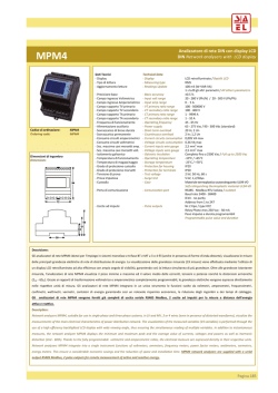
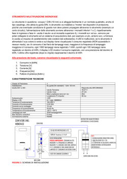
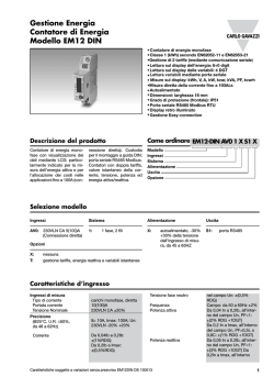
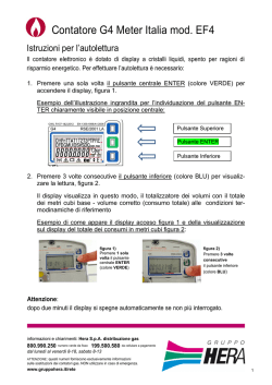
PM10A01KNXFI01010002.doc
Display (readouts)
Safety acc. to EN 50470-1
Energy-meters single-phase direct
connection 80A
PM10A00IRE
Product and Applications Description
Active energy-meters for single-phase alternating current with
either 1, 7 digits digital counters.
These meters have 2 S0 output generating pulses for remote
processing of the energy active and reactive measurements for
2 tariff.
KNX bus connection must be done with KNX interface code
PM00A00IRI
•
•
•
•
•
•
•
•
•
•
•
•
Green backlighted LCD
For direct connection 80 A
7 digits for energy values indication
Accuracy class 1 for active energy according to EN 50470-3
(B)
Accuracy class 2 for reactive energy according to EN
62053-23
Most actrative operating range current (Ist ... Imax.) for direct connection 80 A = 0.02 ... 80 A
The standard versions are designed to be combined with
the communication module
Energy register zero setting (NO MiD)
Energy register for import and export
Instantaneous power active and reactive display
Sealable terminal covers
2 DIN modules wide (36 mm)
• Indoor meter - yes
• Degree of pollution - 2
• Operational voltage V 300
• Display type LCD n° digits 7 (1 decimal digit dimensions
mm x mm 6.00 x 3
Safety acc. to EN 50470-1
• Active energy: 1 display, 7-digit tariffs 1-2 kWh 000000.0 ...
999999.9
+ display import or export (arrow) overflow kWh 999999.9 ...
000000.0
• AC voltage test (EN 50470-3, 7.2) kV 4
• Impulse voltage test 1.2/50 µs-kV 6
• Protection class (EN 50470) class II
• Housing material flame resistance UL 94 class V0
• Reactive energy: 1 display, 7-digit tariffs 1-2 kvarh
000000.0 ... 999999.9
+ display import or export (arrow) overflow kvarh 999999.9 ...
000000.0
Adaptor for Communication
• Instantaneous active power: 1 display, 3-digit W, kW or
MW 000 ... 999
• EIB-KNX EIB-standard - up to 9.600 bps
Environmental conditions
•
•
•
•
•
•
•
Mechanical environment - M1
Electromagnetic environment - E2
Operating temperature °C -25 ... +55
Limit temperature of transportation and storage °C -25 ... +70
Relative humidity (not condensation) 80%
Vibrations 50 Hz sinusoidal vibration amplitude mm ±0.075
Degree protection housing when mounted in front (terminal) IP51(*)/IP20
• Instantaneous reactive power: 1 display, 3-digit var, kvar or
Mvar 000 ... 999
• Instantaneous tariff measurement – 1
1 display, 1-digit - T1 or T2
• Display period refresh s 1
Mounting and Wiring hints
Device is intended to be used indoor in dry places.
Terminals, connections and command/visualisation elements
IMPORTANT:
Overall Dimensions:
Technical Data
• This device must be installed only by a qualified electrician.
• Install in conformity to SELV installation rules.
• The applicable safety and accident prevention regulations must be observed.
• The device must not be opened. Any faulty devices
should be returned to manufacturer.
• For planning and construction of electric installations, the
relevant guidelines, regulations and standards of the respective country are to be considered.
General characteristics
•
•
•
•
For further information please visit www.eelectron.com
Housing DIN 43880 DIN 2 modules
Mounting EN 60715 35 mm DIN rail
Depth 70 mm
Reference standard active energy - EN 50470-1-3, reactive
energy - pulse output EN 62053-23-31
Operating features
• Connectivity to single-phase network n° wires 2
• Storage of energy values and configuration digital display
(EEPROM) - yes
• Display tariffs identifier for active and reactive energy n° 2
T1 and T2
Circuits Diagram:
Supply
• Rated control supply voltage Un VAC 230
• Operating range voltage V 184 ... 276
• Rated frequency fn Hz 50
Overload capability
• Voltage Un continuous V 276 momentary (1 s) V 300
• Current Imax continuous A 80 momentary (10 ms) A 2400
Measuring accuracy
At 23 ±1°C, referred to nominal values
• Active energy and power acc.to EN 50470-3 % ±1 (B)
• Reactive energy and power acc.to EN 62053-23 % ±2
Measuring input
•
•
•
•
•
Type of connection phase/N - direct
Operating range voltage phase/N V 184 ... 276
Current Iref A 15
Current Imin A 0.75
Operating range current (Ist ... Imax) direct connection A
0.025 ... 80
• Frequency Hz 50
• Input waveform - sinusoidal
• Starting current for energy measurement (Ist) mA 25
Sealable Terminal Covers:
Pulse output S0 acc.to EN 62053-31
•
•
•
•
Pulse output for active and reactive energy T1 and T2 - yes
Pulse quantity imp/kWh 1000
Pulse duration ms 30 ±2 ms
Required voltage min. (max.) VAC (DC) 5 ... 230 ±5% (5 ...
300)
• Permissible current pulse ON (max. 230 V AC/DC) mA 90
• Permissible current Impuls OFF (leakage cur. max. 230 V
AC/DC) µA 1
Optical interfaces
• Front side (accuracy control) LED imp/kWh 1000
eelectron spa
Email: [email protected]
Web: www.eelectron.com
PM10A01KNXFI01010002.doc
Sicurezza secondo EN 50470-1
Visualizzazione (lettura)
• Installazione per interni - si
• Classe inquinamento - 2
• Tensione di funzionamento V 300
Contatore Monofase a connessione diretta 80A
PM10A00IRE
Sicurezza secondo EN 50470-1
•
•
•
•
•
Tensione di prova (EN 50470-3, 7.2) kV 4
Prova tensione di impulso 1.2/50 µs-kV 6
Classe di protezione (EN 50470) classe II
Resistenza della custodia alla fiamma UL 94 classe V0
Protezione meccanica - sigillo fra custodia e base
Descrizione sintetica del prodotto e suo funzionamento
Moduli aggiuntivi per la comunicazione
Contatori di energia attiva per corrente alternata monofase con numeratori digitali fino a 7 cifre.
Questi contatori presentano 2 uscite S0 e 2 tariffe che
generano impulsi per l’elaborazione remota delle misurazioni dell’energia attiva e reattiva istantanea.
La connessione al bus KNX è realizzata mediante
l’interfaccia PM00A00IRI
• Visualizzatore a cristalli liquidi con sfondo illuminato di
colore verde
• Collegamento diretto a 80 A
• Display da 7 digit per i valori dell’energia totalizzata
• Classe 1 di precisione per energia attiva secondo la
norma EN 50470-3 (B)
• Classe 2 di precisione per energia reattiva secondo la
norma EN 62053-23
• Campo di corrente (Ist ... Imax) per connessione diretta
80 A = 0.02 ... 80 A
• Versioni standard predisposte per essere abbinate al
modulo per la comunicazione
• Registri contatori azzerabili (NO MiD)
• Registri d’energia assorbita o erogata
• Indicazione della potenza momentanea attiva e reattiva
• Copertura morsetti piombalile
• 2 moduli DIN (36 mm)
• EIB-KNX EIB-standard - fino a 9.600 bps
Condizioni ambientali
•
•
•
•
Ambiente meccanico - M1
Ambiente elettromagnetico - E2
Temperatura d’impiego °C -10 ... +55
Limite della temperatura di immagaz. e trasporto °C -25
... +70
• Umidità relativa (non condensata) % _80
• Vibrazioni ampiezza vibrazioni sinusoidali 50 Hz mm
±0.075
• Grado di protezione apparecchio montato frontalmente
(morset ti) - IP51(*)/(IP20)
Posizione indicatori ed elementi di comando
Dimensioni:
Dati tecnici
• Display LCD n° digits 7 (1 decimale) dimensione digit
mm x mm 6.00 x 3
• Energia attiva: 1 indicatore, 7 cifre 2 tariffe kWh
000000.0 ... 999999.9
+ indicazione assorbita o erogata (freccia) flusso massimo
kWh 999999.9 ... 000000.0
• Energia reattiva: 1 indicatore, 7 cifre 2 tariffe kvarh
000000.0 ... 999999.9
+ indicazione assorbita o erogata (freccia) flusso massimo
kvarh 999999.9 ... 000000.0
• Potenza attiva istantanea: 1 indicatore, 3 cifre W, kW o
MW 000 ... 999
• Potenza reattiva istantanea: 1 indicatore, 3 cifre var,
kvar o Mvar 000 ... 999
• Tariffa attuale - 1
1 indicatore, 1 cifra - T1 o T2
• Ciclo di visualizzazione s 1
Avvertenze per l‘installazione
L’apparecchio deve essere impiegato per installazione in
ambienti chiusi e asciutti.
IMPORTANTE
• L’apparecchio deve essere installato e messo in servizio da un installatore abilitato.
• Devono essere osservate le norme in vigore in materia
di sicurezza e prevenzione antinfortunistica.
• Installare il prodotto senza compromettere la sicurezza
SELV del BUS
• L’apparecchio non deve essere aperto. Eventuali apparecchi difettosi devono essere fatti pervenire alla
sede competente.
Caratteristiche generali
•
•
•
•
Custodia DIN 43880 DIN 2 moduli
Fissaggio EN 60715 35 mm binario DIN
Profondità mm 70
Norme di riferimento energia attiva - EN 50470-1-3
energia reattiva - impulso di uscita EN 62053-23-31
Funzionamento
• Connessione a rete monofase n° fili 2
• Memorizzazione energia misurata e configurazione a
mezzo numeratore digitale (EEPROM) - si
• Tariffe per energia attiva e reattiva n° 2 T1 o T2
Per ulteriori informazioni visitate: www.eelectron.com
Schemi di Collegamento:
Alimentazione
• Tensione nominale di alimentazione Un VAC 230
• Campo di variazione tensione V 184 ... 276
• Frequenza nominale fn Hz 50
• Potenza assorbita (max.) Pv VA (W) _8 (0.6)
Sovraccaricabilità
• Tensione Un permanente V 276 momentanea (1 s) V
300
• Corrente Imax permanente A 80 momentanea (10 ms)
A 2400
Precisione a 23 ±1°C riferimento ai valori nominali
• Energia e potenza attive secondo EN 50470-3 % ±1 (B)
• Energia e potenza reattive secondo EN 62053-23 % ±2
Ingressi di misura
Copertura Morsetti Plombabili:
•
•
•
•
•
Inserzione fase/N - diretta
Campo di tensione fase/N V 184 ... 276
Corrente Iref A 15
Corrente Imin A 0.75
Campo di corrente (Ist ... Imax) connessione diretta A
0.025 ... 80
• Frequenza Hz 50
• Forma d’onda in ingresso - sinusoidale
• Corrente iniziale per la misura di energia (Ist) mA 25
Uscita S0 secondo EN 62053-31
•
•
•
•
Uscita impulso per energia attiva e reattiva - si
Quantità impulso imp/kWh 1000
Durata impulso ms 30 ±2 ms
Tensione necessaria min. (max.) VAC (DC) 5 ... 230
±5% (5 ... 300)
• Corrente consentita impulso ON (max. 230 VAC/DC)
mA 90
• Corrente consentita impulso OFF (corrente di dispersione max. 230 VAC/DC) µA 1
Interfaccia ottica
• Calibratura frontale (controllo di precisione) LED
imp/kWh 1000
eelectron spa
Email: [email protected]
Web: www.eelectron.com
© Copyright 2026 Paperzz