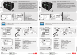
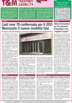
KXDI10 24808870 20-02-14_- 20/02/14 15.00 Pagina 1
KXDI10
ELEMENTI DI AZIONAMENTO E VISUALIZZAZIONE
+Bus
ON
Prog.
1
RUN
2
3
1
2
3
Pulsante di programmazione/LED di programmazione rosso
LED di funzionamento verde
Interruttore manuale
MONTAGGIO DELL’UNITÀ DI COMANDO
I
ATTUATORE DIMMER PER BALLAST
ELETTRONICI (1-10V) - 1 CANALE
CON FUNZIONAMENTO MANUALE
INFORMAZIONI SUL SISTEMA KNX
Questo dispositivo è un prodotto del sistema KNX ed è conforme alle
direttive KNX. Condizione essenziale è un’esperienza approfondita
acquisita con l’addestramento nel sistema BUS.
Il funzionamento del dispositivo dipende dal software utilizzato.
Informazioni dettagliate sul software che può essere caricato e sulla
gamma di funzioni associate a ciascun tipo di software, oltre che sul
software stesso, sono disponibili nel database di prodotti BPT.
Le operazioni di pianificazione, installazione e messa in funzione del
dispositivo vengono eseguite utilizzando software certificato KNX. Il
database di prodotti BPT e le descrizioni tecniche vengono aggiornati
regolarmente e sono reperibili in Internet sul sito www.BPT.it.
FUNZIONE DELL’UNITÀ DI COMANDO
L’attuatore dimmer per ballast elettronici (1-10V) (KXDI10) commuta e
regola la luminosità di lampade fluorescenti attraverso ballast elettronici
con interfaccia 0-10V/1 -10 V e lampade alogene LV attraverso
trasformatori con interfaccia 0-10V/1-10 V.
Il campo della tensione di comando può essere regolato con l’ETS
attraverso un parametro.
Esempio di collegamento
Bus
+ -
L1 N
B
L
A
0-10V
+
L
N
C
0-10V
+
12V AC
G
L
N
D
0-10V
+
F
E
A
B
C
D
E
F
G
Accoppiatore bus (integrato)
Attuatore dimmer per ballast elettronici (1 -10V)
Ballast elettronico con interfaccia 0-10V/1 -10 V
Trasformatore elettronico con ingresso di comando 0-10V/1-10 V
Ad altri dispositivi con interfaccia 0-10V/1 -10 V
Lampade alogene LV
Lampada fluorescente
24808870/20-02-2014
Rischio di lesione fatale dovuta alla corrente elettrica.
Durante l’installazione devono essere osservate le norme di sicurezza
specificate in EN 50105.
Il dispositivo può essere installato soltanto da elettricisti qualificati. In
caso contrario vi è rischio di elettrocuzione.
L’attuatore dimmer per ballast elettronici è un dispositivo montato su
barra DIN ed è montato su una barra DIN.
Non è richiesta una barra dati. Il collegamento del bus è realizzato
attraverso il terminale di collegamento del bus in dotazione con il
dispositivo.
Sul terminale di collegamento del bus viene poi collocato il coperchietto
di protezione a garanzia del rispetto della distanza di sicurezza del cavo
del bus rispetto ai cavi da 230 V.
MESSA IN FUNZIONE DEL’UNITÀ DI COMANDO
Rischio di lesione fatale:
Gli interventi sull’unità possono essere eseguiti soltanto da elettricisti
qualificati. Rispettare i regolamenti vigenti nel paese di utilizzo del
dispositivo, unitamente alle direttive KNX vigenti.
1 Caricare l’indirizzo fisico nell’ingresso binario da ETS via KNX.
2 Eseguire le impostazioni di configurazione in ETS e trasferirle.
DATI TECNICI
Alimentazione dal bus: DC 24 V / circa 17,5 mA
Tensioni di isolamento: AC 4 kV bus/tensione di rete e bus / 0-10
V
AC 4 kV 0-10
V - tensione di rete
Contatto di commutazione: contatto di chiusura, flottante
Dati di connessione:
Corrente nominale: 16 A; carico induttivo a cos ϕ = 0,6
Lampade a incandescenza: 3600 watt
Lampade alogene: 230 V AC 2500 watt
Lampade alogene (LV): max. 2000 W tramite trasformatori elettronici (per
es. 14 MET S 105 W)
Lampade fluorescenti: 3600 VA non compensate
Carico capacitivo: 3600, 200 µF
Protezione: Il contatto di commutazione deve essere protetto da un
sezionatore 16 A collegato in serie.
Durata di servizio: > 50.000 cicli di commutazione al carico nominale 010V/1-10V
Interfaccia: 0-10 V per ballast elettronici dimmerabili, trasformatori MET S
(possono essere regolati tramite parametri)
Capacità di carico: max. 100 mA (max. 50 ballast elettronici, a seconda dei
ballast elettronici)
Tensione di comando min.: 0 V
Temperatura ambiente:
- Esercizio: da -5 °C a +45 °C
- Conservazione: da -25 °C a +55 °C
- Trasporto: da -25 °C a +70°C
- Umidità max.: 93 %
Ambiente
Il dispositivo è progettato per l’uso fino ad un’altitudine d’installazione di
2000 m s.l.m.
KXDI10 24808870 20-02-14_- 20/02/14 15.00 Pagina 2
Connettori:
- Bus: tramite due pin da 1 mm per morsetto di collegamento al bus
- Conduttore sotto tensione e uscita di commutazione: morsetti a vite a
3 vie per max. 2,5 mm2
- Uscita 1-10 V: morsetti a innesto a 2 poli con collegamento a vite per
max. 2,5 mm2
Tipo di protezione: IP 20
Direttive CE: conforme alla Direttiva 73/23/CEE sulla bassa tensione,
conforme alla Direttiva EMC 89/336/CEE
Dimensioni: 90x45x65 mm (HxLxD)
Larghezza del dispositivo: 2,5 TE = 45 mm
OPERATING AND DISPLAY ELEMENTS
+Bus
ON
Prog.
1
RUN
2
3
1
2
3
Programming button/Programming LED, red
Operating LED, green
Manual switch
HOW TO MOUNT THE CONTROL UNIT
Risk of fatal injury from electrical current.
During installation, the safety regulations specified in EN 50105 must
be observed. The device may only be installed by skilled electricians.
Otherwise, there is a risk of fire or electrocution.
EN
DIMMER ACTUATOR FOR ELECTRONIC
BALLASTS (1-10V) - 1 CHANNEL WITH
MANUAL OPERATION
KNX SYSTEM INFORMATION
This device is an KNX system product and conforms to KNX directives.
Detailed expertise gained through training in the BUS system is a
prerequisite.
The function of the device depends on the software used. Detailed
information on which software can be loaded and the range of functions
associated with each type of software, and the software itself, are
available from the BPT product database.
Planning, installation and commissioning of the device are carried out
using KNX-certified software.
The product database and the technical descriptions are updated regularly
and can be found on the Internet at www.BPT.it.
WHAT YOU CAN DO WITH THE CONTROL UNIT
The dimmer actuator for electronic ballasts (1-10V) (KXDI10) dims and
switches fluorescent lamps via electronic ballasts with a
0-10V/1-10 V interface and LV halogen lamps via transformers with a
0-10V/1-10 V interface.
The control voltage range can be set with the ETS via a parameter.
Connection example
Bus
+ -
L1 N
B
L
The Dimmer actuator for electronic ballasts is a DIN rail mounted device and is
mounted onto a DIN rail. A data rail is not required.
The bus connection is carried out via the bus connecting terminal supplied
with the device.
The cable cover is then placed over the bus connecting terminal to guarantee
the safety clearance of the bus cable to the 230 V cables. A maximum of four
core pairs can be connected to the bus connecting terminal.
The cables are connected via terminals:
2 screw terminals for live conductors
1 screw terminal for switched live conductor
2 plug-in terminals for 0-10 V
The cables of the 0-10V/1-10 V control voltage can be connected to the
terminals prior to installing the device and then inserted at a later date.
Caution!
Disconnect the mains voltage before connecting the device to the
load. Do not insert the terminal when it is under load.
All the devices that are mounted next to the control unit must at least be fitted
with basic insulation. The green operating LED only lights up if the application
program has been loaded correctly into the device.
The switch output (switched live conductor) can also be operated manually
without bus voltage using the manual switch.
HOW TO PUT THE CONTROL UNIT INTO OPERATION
Risk of fatal injury:
All work carried out on the unit may only be performed by skilled
electricians. Observe the regulations valid in the country of use, as
well as the valid KNX directives.
1 Load the physical address into the device from the ETS via KNX.
2 Make the configuration settings in ETS and transfer them.
A
0-10V
TECHNICAL DATA
+
L
N
C
0-10V
+
12V AC
G
L
N
D
0-10V
+
F
A
B
C
D
E
F
G
E
Bus coupler (built-in)
Dimmer actuator for electronic ballasts (1-10V)
Electronic ballast with 0-10V/1-10 V interface
Electronic transformer with 0-10V/1-10 V control input
To other devices with 0-10V/1-10 V interface
LV halogen lamps
Fluorescent lamp
Power supply from the bus: DC 24 V / approx. 17.5 mA
Insulation voltages: AC 4 kV bus/mains voltage and bus / 0-10
V
AC 4 kV 0-10
V - mains voltage
Switch contact: Make contact, floating
Connection data:
Nominal current: 16 A; inductive load at cos ϕ = 0.6
Incandescent lamps: 3600 watt
Halogen lamps: 230 V AC 2500 watt
Halogen lamps (LV): max. 2000 W via electronic transformers (e. g. 14 MET
S 105 W)
Fluorescent lamps: 3600 VA uncompensated
Capacitive load: 3600, 200 µF
Protection The switch contact must be protected by a series connected
16 A circuit-breaker.
Service life: > 50,000 switching cycles at nominal load 0-10V/1-10V
Interface: 0-10 V for dimming electronic ballasts, MET S transformers (can
be set via parameters)
KXDI10 24808870 20-02-14_- 20/02/14 15.00 Pagina 3
Loading capacity: max. 100 mA (max. 50 electronic ballasts; depending on
electronic ballasts)
Min. control voltage: 0 V
Ambient temperature:
- Operation: -5 °C to +45 °C
- Storage: -25 °C to +55 °C
- Transport: -25 °C to +70 °C
- Max. humidity: 93 %
Environment
The device is designed for use at a height up to 2000 m
above sea level.
Connections
- Bus: via two 1 mm pins for bus connecting terminal
- Live conductor and switch output: 3-gang screw terminals for max.
2.5 mm2
- 1-10 V output: 2-pole plug-in terminals with screw connection for
max. 2.5 mm2
Type of protection: IP 20
EC directives: complies with low-voltage directive 73/23/EEC, complies
with EMC directive 89/336/EEC
Dimensions: 90x45x65 mm (HxWxD)
Device width: 2,5 TE = 45 mm
KXDI10 24808870 20-02-14_- 20/02/14 15.00 Pagina 4
© Copyright 2026 Paperzz