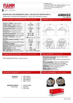
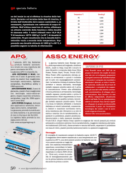
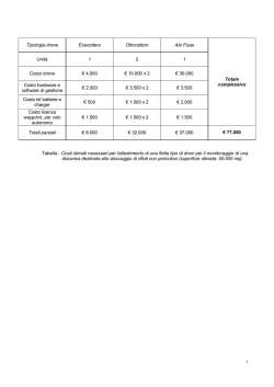
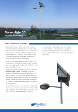
MANUALE ISTRUZIONI
INSTRUCTION MANUAL
REGOLATORE DEL FATTORE DI POTENZA SERIE EPF
AUTOMATIC POWER FACTOR REGULATOR EPF SERIES
I
DESCRIZIONE
Il regolatore di rifasamento serie EPF è stato progettato con tecnologia per l’elaborazione dei segnali tale da assicurare un
controllo accurato di tutte le grandezze elettriche dell’impianto come : tensione, corrente, cosφ, THD % in corrente e
TEMPERATURA ambiente lato sonda, Potenza Attiva, Reattiva e Apparente, valori max assunti dalle misure e tramite un
affidabile algoritmo di calcolo, un utilizzo ottimale dei condensatori e contattori tenendo conto dei fenomeni di distorsione degli
impianti industriali. Utilizzando tecniche digitali di filtraggio dei segnali, esso è in grado di separare dalle altre componenti
armoniche le sole componenti sinusoidali fondamentali di tensione e corrente, sulle quali è misurato lo sfasamento.
Il regolatore del fattore di potenza serie EPF, visualizza tutte le misure sul display LCD retroilluminato in modo da assicurare
una agevole lettura dei dati in qualsiasi condizione ambientale.
Proprio attraverso la caratteristica di poter visualizzare in carattere alfanumerico la grandezza elettrica misurata o il tipo di
allarme e sottostante il corrispondente valore, permette una semplicità ed una chiarezza di utilizzo per qualsiasi tipologia di
utenza. Mediante quattro tasti utente è possibile accedere alla regolazione dello strumento, inserire manualmente delle batterie,
visualizzare le misure e gli allarmi.
GB DESCRIPTION
The Automatic Power Factor Regulator EPF Series has been designed with a technology for signal elaboration to assure an
accurate control of all use’s circuit electrical parameters as: mains voltage, current, cosφ, THD % in the current, ambient
temperature at sound side, Active-Reactive-Apparent Power, measured max values and through a calculation algorithm
optimizes the switching logic of the steps taking into account the harmonic distortion phenomenons in the user’s circuit. By
means of digital and signal filtering techniques, it separates current and voltage fundamental sinusoidal components from the
others and measures cosφ between them.
Power Factor Regulator EPF Series displays all measured values on the back lighted display in a way to easily read the data in
all ambient conditions.
The upper line of the display shows the name of the parameter being measured and in the lower line the corresponding value.
Due to these features and the use of clear alpha-numeric texts, the user’s interface is very simple and direct. Measurements
and alarm messages can be read without decoding, thereby reducing the need for service personnel training
Four keys allow access to programming the regulator, reading measurements and alarms, and manual switching-in of steps.
I
INSTALLAZIONE
Il regolatore di rifasamento serie EPF deve essere installato su linea trifase o monofase con l’inserzione in quadratura e
frequenza di rete di 50-60 Hz tramite un TA per la corrente di linea (L1), autoalimentato tramite le restanti fasi (L2-L3). Gli
ingressi di alimentazione e quant’altro devono essere protetti con fusibili dimensionati opportunamente in base alle norme
vigenti ed agli assorbimenti previsti. Le uscite di comando devono essere opportunamente collegate ai rispettivi organi di
intervento protetti a loro volta, come tutte le parti di potenza dell’impianto.
I contatti per il comando delle batterie sono NO con comune C interlacciato, mentre il contatto di allarme è settabile NO-NC –
FAN indipendente.
1
Enerlux srl • via Guido Rossa, 8 • 46019 VIADANA (MN) Italy • tel.+39 0375 785887 fax+39 0375 785877
IGB
MANUALE ISTRUZIONI
INSTRUCTION MANUAL
GB INSTALLATION
EPF series regulator must be installed on three-phase or single-phase electric system with the insertion in the quadrature and in
a network frequency of 50-60 Hz through a CT for line current (L1), supplied through the remaining phases (L2-L3).The mains
inputs must be protected by suitably designed fuses basing on the current standards and the foreseen absorptions. The control
outputs must be connected to their tripping devices that must be protected as all the other power parts of the installation.
Output contacts are normally open (NO) with common on C terminal. The alarm contact can be set independently as NO –NC –
FAN.
I FUNZIONAMENTO
Completate le operazioni di SETUP il display visualizza i dati calcolati nell’impianto e premendo il pulsante SET, si potranno
verificare consecutivamente le grandezze elettriche quali: Tensione di linea, Corrente misurata sul TA, ∆ Kvar mancati alla
compensazione impostata (sia capacitivo sia induttivo).
Regolatore EPF6T
Pag.
1
2
3
4
5
6
7
8
9
10
Visualizzazione
Power Factor
VOLTAGE
CURRENT
Delta Power
THD I%
Week cosφ
Ifo
Iharm
SET COSφ
THD I% MAX
Vrms MAX
Irms MAX
TEMP
T MAX
T.START FAN
Descrizione
Fattore di potenza
Tensione RMS
Corrente RMS
Potenza reattiva in eccesso e/o difetto rispetto al SET impostato
Distorsione armonica percentuale in corrente
Fattore di potenza medio settimanale
Corrente fondamentale
Corrente armonica
Impostazione del valore di regolazione del cosφ in funzionamento automatico (tale parametro è
modificabile solo in funzionamento manuale)
Max valore picco distorsione armonica in corrente
Massimo valore raggiunto tensione Vrms
Massimo valore raggiunto corrente Irms
Temperatura Istantanea
Valore di temperatura massimo raggiunto
Temperatura partenza soglia ventilazione (azionamento del relè dedicato a FAN se impostato
con tale funzione)
Regolatore EPF8T – EPF12T
Pag.
1
2
3
4
5
6
7
Visualizzazione
Power Factor
VOLTAGE
CURRENT
Delta Power
THD I%
Week cosφ
Ifo
Iharm
TEMP
T.START FAN
SET COSφ
P
Q
A
THD I% MAX
Vrms MAX
Irms MAX
T MAX
P MAX
Q MAX
A MAX
Descrizione
Fattore di potenza
Tensione RMS
Corrente RMS
Potenza reattiva in eccesso e/o difetto rispetto al SET impostato
Distorsione armonica percentuale in corrente
Fattore di potenza medio settimanale
Corrente fondamentale
Corrente armonica
Temperatura istantanea
Temperatura partenza soglia ventilazione (azionamento del relativo reklè se impostato FAN)
Impostazione del valore di regolazione del cosφ in funzionamento automatico (tale parametro è
modificabile solo in funzionamento manuale)
Potenza attiva
Potenza reattiva
Potenza apparente
Max valore picco distorsione armonica in corrente
Massimo valore raggiunto tensione Vrms
Massimo valore raggiunto corrente Irms
Valore di temperatura massimo raggiunto
Potenza attiva massima raggiunta
Potenza reattiva massima raggiunta
Potenza apparente massima raggiunta
Per resettare le memorizzazioni dei valori massimi misurati premere il pulsante UP× e confermare il reset con il pulsante
DOWNØ. Dopo 30 secondi di visualizzazione del parametro selezionato, il controllore ritorna alla visualizzazione della pagina
principale.
Per inserire o disinserire le batterie è necessario portare il regolatore in funzionamento manuale, posizionarsi nella pagina di
visualizzazione del Cosφ; premere il pulsante UP× o DOWNØ per selezionare la batteria, ed infine premere il pulsante SET per
confermare la selezione. Allo scopo di verificare che la batteria selezionata sia effettivamente quella che si vuole inserire o
disinserire viene visualizzato il suo valore, espresso in Kvar, impostato nel Setup. Nella visualizzazione sottostante sono
riportate le manovre totali di inserzione effettuate per ogni singola batteria; sono possibili in questo modo delle diagnosi e delle
stime di usura delle varie parti (tale dato non è resettabile)
L’inserzione manuale delle batterie comporta il disinserimento della funzione di regolazione automatica, ma consente
comunque il controllo di tutte le altre misure e degli allarmi. Nel caso in cui avvenga un’interruzione della tensione di
alimentazione lo stato delle batterie in manuale viene memorizzato nella memoria interna non volatile; tale operazione consente
al regolatore di effettuare l’inserimento delle stesse batterie non appena l’alimentazione viene ripristinata.
2
Enerlux srl • via Guido Rossa, 8 • 46019 VIADANA (MN) Italy • tel.+39 0375 785887 fax+39 0375 785877
IGB
MANUALE ISTRUZIONI
INSTRUCTION MANUAL
Per passare dal funzionamento automatico al funzionamento manuale e viceversa, è necessario premere il pulsante MAN/AUT
per 5 sec e conseguentemente l’accensione del corrispettivo led di segnalazione.
In funzionamento automatico tutte le regolazioni avvengono in completa sintonia dei parametri impostati inserendo e/o
disinserendo le batterie di rifasamento tali da raggiungere il Cosφ impostato. Il programma del controllore permette di
monitorare ed eventualmente comunicare gli allarmi come:
-HIGH VOLTAGE: tensione di linea superiore al 110% della nominale per 15 min; intervento del relè di allarme (se non
configurato come batteria)
-LOW VOLTAGE: tensione di linea inferiore al 85% della nominale per 5 sec; intervento relè di allarme (se non configurato
come batteria)
-HIGH CURRENT: corrente superiore al 110% della nominale per 2 min
-LOW CURRENT: corrente inferiore al 8% della nominale per 5 sec (nessuna inserzione di batterie e disinserzione delle
batterie inserite se l’allarme permane per più di 2 min)
-UNDER COMPENS: sottocompensazione cosφ per 15 min; intervento relè di allarme (se non configurato come batteria)
-OVER COMPENS: sovracompensazione cosφ per 2 min (disinserzione delle batterie per salvaguardare l’integrità dei
condensatori); intervento del relè di allarme (se non configurato come batteria)
- HIGH THD%: distorsione armonica percentuale superiore al limite di soglia impostato; intervento del relè di allarme e
disinserimento in sequenza delle batterie inserite
- OVER THD%: distorsione armonica percentuale massima istantanea superiore al limite di soglia impostato; intervento del relè
di allarme e disinserimento istantaneo in sequenza delle batterie inserite
- OVER TEMPERATURE: temperatura lato sonda superiore al valore massimo impostato; intervento del relè di allarme e
disinserimento in sequenza delle batterie inserite
- MAIN FAILURE: tensione di rete mancante o inferiore al valore minimo di sistema sull’ingresso voltmetrico
In caso di allarme è attivato il relè omonimo (NO – NC) con logica di rientro al cessare dello stesso.
Per inserire o disinserire le batterie impostate FIX è necessario ripetere le stesse operazioni per l’attivazione di una batteria in
manuale e successivamente passare in automatico. In tale modo il sistema utilizza automaticamente le batterie disponibili
trascurando le batterie impostate FIX. Affinché sia utilizzabile la batteria in modalità FIX è necessario impostare tale modalità
nel setup della batteria.
Nello scopo di ottenere le massime prestazioni dell’impianto il regolatore provvede a calcolare l’esatto momento del passaggio
per lo zero della tensione per inserire/disinserire esattamente i banchi di condensatori in assenza di tensione; in questo modo si
evitano i pericolosi archi dovuti al carico capacitivo in manovra sulla linea.
DETTAGLI SUL FUNZIONAMENTO BATTERIA FIX
Impostando la batteria in modalità FIX il dispositivo non la utilizza per la regolazione in automatico. In tale modalità la batteria
può essere attivata per consentire una funzione di rifasatore fisso ed il dispositivo la ignora utilizzando le altre per la
compensazione.
Per inserire o disinserire le batterie impostate FIX è necessario ripetere le stesse operazioni per l’attivazione di una batteria in
manuale e successivamente passare in automatico. In tale modo il sistema utilizza automaticamente le batterie disponibili
trascurando le batterie impostate FIX. Affinché sia utilizzabile la batteria in modalità FIX è necessario impostare tale modalità
nel setup della batteria.
In funzionamento automatico pertanto avviene la regolazione utilizzando altre batterie disponibili; nei casi di allarme che
pregiudicano i condensatori, il dispositivo disattiva nella stessa modalità anche le batterie impostate come FIX
salvaguardandone l’integrità, per poi riconnetterle al cessare dell’allarme.
DETTAGLI SUL FUNZIONAMENTO PROTEZIONE THD
L’algoritmo interno dello strumento monitorizza costantemente l’andamento della distorsione armonica in corrente sul punto di
installazione del trasformatore amperometrico. Se il THD istantaneo è maggiore della soglia di impostazione THERM, il sistema
decrementa progressivamente il valore di SENS con passo 1 secondo con logica integrale fino ad arrivare a 0 dove avviene lo
sgancio in sequenza delle batterie inserite. Il nuovo inserimento potrà avvenire solamente se le condizioni di THD si riportano al
di sotto della soglia THERM impostata. Nel caso che il THD istantaneo sia oscillante nelle vicinanze della soglia di
impostazione THERM, il dispositivo effettua un decremento per la durata del tempo di THD istantaneo maggiore della soglia, ed
un incremento, fino al massimo dell’impostazione del SENS iniziale, nel caso che il THD istantaneo si riporti successivamente
al di sotto della soglia di controllo. Tale algoritmo permette di simulare un riscaldamento del condensatore dovuto alle
armoniche pertanto una disinserzione delle batterie nel caso del perdurare della situazione, evitando pericolosi pendolamenti e
proteggendo i condensatori.
Se si desidera comunque che il dispositivo reinserisca istantaneamente le batterie appena il THD istantaneo scende al di sotto
della soglia è necessario impostare il parametro SENS DOWN ad ON.
Intervento istantaneo
OVER THD I%
Soglia OVER THD
Soglia THERM THD
Tempo
Incremento SENS THD
Enerlux srl • via Guido Rossa, 8 • 46019 VIADANA (MN) Italy • tel.+39 0375 785887 fax+39 0375 785877
3
IGB
MANUALE ISTRUZIONI
INSTRUCTION MANUAL
GB
OPERATION
Once the SETUP procedure is completed the display shows data related to the plant.
Keeping pushed the SET key you could read and display the various pages :
EPF6T Regulator
Page
1
2
3
4
5
6
7
8
9
10
Display
Power Factor
VOLTAGE
CURRENT
Delta Power
THD I%
Week cosφ
Ifo
Iharm
SET COSφ
THD I% MAX
Vrms MAX
Irms MAX
TEMP
T MAX
T.START FAN
Description
Power factor
RMS Voltage
RMS Current
Excessive and/or detective reactive power in comparison to SET
Percentage harmonic distortion in current
Weekly average power factor
Fundamental current
Harmonic current
Cosφ regulation value setting with automatic operation (this parameter can be motified only
with manual operation)
Harmonic distortion max peak value in current
Voltage max reached value Vrms
Current maximum reached value Irms
Instantaneous Temperature
Temperature max reached value
Fan threshold starting temperature (tripping of the FAN relay if set with this function)
Regolatore EPF8T – EPF12T
Page
1
2
3
4
5
6
7
Display
Power Factor
VOLTAGE
CURRENT
Delta Power
THD I%
Week cosφ
Ifo
Iharm
TEMP
T.START FAN
SET COSφ
P
Q
A
THD I% MAX
Vrms MAX
Irms MAX
T MAX
P MAX
Q MAX
A MAX
Description
Power factor
RMS Voltage
RMS Current
Excessive and/or detective reactive power in comparison to SET
Percentage harmonic distortion in current
Weekly average power factor
Fundamental current
Harmonic current
Instantaneous Temperature
Fan threshold starting temperature (tripping of the FAN relay if set with this function)
Cosφ regulation value setting with automatic operation (this parameter can be motified only
with manual operation)
Active power
Reactive power
Apparent power
Harmonic distortion max peak value in current
Voltage max reached value Vrms
Current maximum reached value Irms
Temperature max reached value
Max reached active power
Max reached reactive power
Max reached apparent power
To reset max measured value keep UP× key pushed and confirm reset with DOWNØkey. After 30 seconds the parameter is
displayed, regulator returns to the main page.
To switch in or switch off the various batteries you should firstly select MANUAL operation, then go to the page of cosφ
visualization; then push the UP× and DOWNØ keys to select the step, then press SET to confirm selection. To verify that the
selected step is the one that must be switched-in or switched-off the display shows its value expressed in kVAr set in the Setup.
In the subsequently displaying the total switchings in of each step are reported; in this way an evaluation of the state of wear of
capacitors and contactors could be made (this is not a resettable value because it shows the wear state of the system).
The manual switching-in of the various steps stops the automatic regulation, but permits to display all measurements and
alarms.
The manual switching of the various steps imply the switching off of the automatic operation, but it permits the control of all the
other measurements and alarms. In case there would be an interruption of mains voltage interruption, the status of the various
steps in manual operation is memorized in the internal memory not by the volatile one; this operation permits to the regulator to
reconnect the same steps that had been manually connected ones mains is restored.
To change automatic operation to the manual one or vice versa, press MAN/AUT key for 5 seconds long and the consequently
the lighting of the related signalization led
During automatic operation all the regulations take place in a complete tune with the parameters set switching in or switching off
the power factor correction steps to reach the set cosφ. The software of this regulator permit to show and eventually
communicate the alarms as:
HIGH VOLTAGE – Line voltage exceeding 110% the rated voltage for 15 min. long; tripping of alarm relay (if it is not
configurated as the step);
LOW VOLTAGE – Line voltage less than 85% the rated voltage for 5 sec. long; tripping of alarm relay (if it is not configurated as
the step);
4
Enerlux srl • via Guido Rossa, 8 • 46019 VIADANA (MN) Italy • tel.+39 0375 785887 fax+39 0375 785877
IGB
MANUALE ISTRUZIONI
INSTRUCTION MANUAL
HIGH CURRENT – Current exceeding 110% the rated value for 2 min.long;
LOW CURRENT – Current is lower than 8% of rated value for 5 sec. long (no switching in or switching off if the alarm persists
for a time exceeding 2 minutes).
UNDER COMPENSATION – Under compensation cosφ for 15 min.long I(f it is not configurated as the step);
OVER COMPENSATION – Over compensation cosφ for 2 min.long (Switching off of the various steps to safeguard the
integrity of the capacitors); tripping of alarm relay (if it is not configurated as the step);
HIGH THD% - Percentage of harmonic distortion higher than the set threshold limit; alarm relay tripping and sequently switching
off of the switched in steps.
OVER THD% - Instantaneous max. percentage of harmonic distortion higher than the set threshold limit; alarm relay tripping
and sequently switching off of the switched in steps.
OVER TEMPERATURE – Sound side temperature higher than the maximum set value; tripping of alarm relay and sequently
switching off of the switched in steps.
MAIN FAILURE: No network voltage or voltage lower than the min. value of the system on the voltmetric input.
In case of alarm the corresponding relay is activated (NO-NC). It automatically resets when alarm condition is removed.
To switch-in or switch off batteries set as FIX, the same operations must be carried out to activate manually a battery and
subsequently change to automatic mode. In this way system is using automatically available batteries not considering batteries
set as FIX. To use battery as FIX this mode in battery set up must be set.
To have maximum plant operation power factor regulator calculate exact moment of zero voltage passage to switch-in/switch-off
capacitor batteries without voltage; in this way we avoid dangerous arches caused by capacitive charge during switching on
line.
DETAILS ABOUT FIX BATTERY MODE
Setting battery in FIX mode regulator is not using it in automatic mode. In this mode battery can be activated to permit fix battery
function and regulator is not considering it using the other ones for power factor correction.
To switch-in and switch-off batteries set as FIX, the same operations to activate manually a battery must be carried out and
subsequently change to automatic mode. In this way system is using automatically available batteries not considering set FIX
ones. To use a battery in FIX mode, set this mode in battery setup.
In automatic mode regulation happen using available batteries; in case of alarms related to capacitors, regulator switch-off also
FIX batteries, don’t damaging their integrity, to re-connect them at alarm stopping.
DETAILS ABOUT THD PROTECTION OPERATION
The internal algorithm of the device reads constantly the harmonic current distortion flow at the point of amperometric
transformer installation. If the instantaneous THD is higher than the set threshold TERM, the system progressively decrease the
SENS value with pitch 1 following an integral logic till arriving to 0 value, at which the inserted steps are sequently disconnected.
The new switching in of the various steps could be made only if THD values are reach a value under the set THERM threshold.
In case the instantaneous THD value is variable and close to the THERM threshold, the device makes a decrease during the
time in which instantaneous THD is higher than the threshold, and an increase, till the max. setting of the initial SENS, in case
the THD value returns under the control threshold. This algorithm permits to simulate a heating of the capacitor due to
harmonics, and subsequently the disconnection of the steps if the situation continues to be the same, avoiding in this way
dangerous hunting and protecting in this way the capacitors.
However, if you need a system that re-switches in immediately the various steps when instantaneous THD value is under the
threshold you have to set the SENS DOWN parameter as ON.
Decrease SENS THD
THD I%
Istantaneous tripping
OVER THD I%
OVER THD threshold
TERM THD threshold
Time
Increase SENS THD
5
Enerlux srl • via Guido Rossa, 8 • 46019 VIADANA (MN) Italy • tel.+39 0375 785887 fax+39 0375 785877
IGB
MANUALE ISTRUZIONI
INSTRUCTION MANUAL
I PARAMETRIZZAZIONE
Il regolatore serie EPF permette due tipologie di menù: base (PAR SETUP) e avanzato (MAIN SETUP).
PAR SET UP Menu
Questo menù risulta di facile accesso e permette di settare quei parametri strettamente necessari all’installazione finale presso
l’utenza ovvero: TA, SENS, OVER Temperature, THERM THD I%, OVER THD I%, SENS THD I, SENS DOWN. Per accedere è
sufficiente tenere premuto il pulsante SET in funzionamento manuale e con tutte le batterie disinserite nella pagina di
visualizzazione del POWER FACTOR, fino alla comparsa della visualizzazione PAR SETUP.
Per avanzare nei parametri modificabili in tale menù è sufficiente premere il pulsante SET e per cambiarne il valore premere i
pulsanti UP × o DOWN Ø.
Le regolazioni da effettuare quindi in tale menù sono:
PAR TA=>
impostazione del rapporto del trasformatore amperometrico collegato in linea
SENS=>
impostazione della sensibilità di intervento per ogni singolo gradino sulla regolazione del cosφ
OVER TEMP=> impostazione della temperatura massima di funzionamento oltre la quale avviene l’intervento dell’allarme e lo
sgancio delle batterie inserite
THERM THD I%=> impostazione del valore di allarme protezione termico THD % in corrente oltre il quale, in base al tempo di
SENS THD%, avviene lo sgancio in sequenza delle batterie inserite
OVER THD I%=> impostazione del valore di intervento allarme istantaneo THD % in corrente; istantaneamente a tale
situazione, condizione di risonanza, avviene lo sgancio delle batterie inserite
SENS THD I%=>
impostazione tempo di intervento allarme THD % in corrente
SENS DOWN=> impostazione del funzionamento ripristino di funzionamento al cessare dell’allarme (se impostato ON al
cessare dell’allarme istantaneamente abilita l’inserimento delle batterie, se impostato ad OFF inverte il tempo
rimanente di SENS THD fino all’abilitazione inserimento batterie). Per modificare premere e tenere premuto il
pulsante SET ed il pulsante UP × o DOWN Ø.
NOTA: La regolazione della sensibilità di intervento per ogni singolo gradino (Sens) avviene tramite l’impostazione del rispettivo
valore di intervento, compatibilmente con i tempi di riconnessione (RC TIME); si deduce quindi che più piccolo è il valore
impostato più rapida sarà la regolazione del fattore di potenza.
L’impostazione del parametro THERM THD I% è legata alle caratteristiche tecniche del condensatore installato
sull’impianto; verificare quindi i dati forniti dal costruttore per il limite di sopportazione contenuto armonico in corrente
del condensatore (es: 50% per 60 sec)
MAIN SET UP Menu
Questo menù serve per configurare i parametri strettamente legati al quadro di rifasamento quali: tipologia di batterie, tensione
nominale dei condensatori, tempo di riconnessione delle batterie, frequenza della rete, tipo di rete (monofase o trifase) e
configurazione relè di allarme (NO-NC).
Per accedere al Setup avanzato è sufficiente entrare nel Setup base tenendo premuto il pulsante SET in funzionamento
manuale e con tutte le batterie disinserite nella pagina di visualizzazione del POWER FACTOR, fino alla comparsa della
visualizzazione PAR SETUP, poi premere e tener premuto il pulsante SET fino alla comparsa della visualizzazione MAIN
SETUP.
Le regolazioni da effettuare quindi in tale menù sono:
POWER CAP n°=> impostazione del valore nominale della potenza della batteria installata nella posizione indicata (espresso in
Kvar alla tensione nominale). Per impostare una batteria in funzionalità FIX portare il valore a 0.0 e premere nuovamente il
pulsante DOWN fino alla comparsa della dicitura.
CAP VOLTAGE=> impostazione del valore nominale delle batterie installate (fornita dal costruttore)
CAP RC TIME=> tempo minimo di riconnessione della stessa batteria in base ai dispositivi di scarica sui condensatori
ALARM RELAY=> impostazione funzionamento relè di allarme (NO-NC-FAN). Solo nel caso di impostazione del relè di allarme
in modalità FAN è possibile impostare l’ultima batteria del dispositivo in modalità Allarme.
EXTERNAL TV=> impostazione configurazione dell’ingresso voltmetrico con trasformatore tensione su linea esterna; se
presente inserire i valori del primario e del secondario del trasformatore
LINE FREQ=>
frequenza di linea (50 o 60Hz)
LINE TYPE=>
tipologia di inserzione (monofase o trifase)
SYSTEM MODE=> impostazione di installazione dispositivo su impianti per la misura su 2 o 4 quadranti
Abilitando la funzionalità di EXTERNAL TV il dispositivo consente l’inserimento di un trasformatore di tensione a monte del
circuito di lettura voltmetrica. Per fare ciò si rende necessario inserire il valore del rapporto di riduzione (RATIO_TV).
Es. se il TV è caratterizzato da un ratio di 200:1 il parametro RATIO_TV dovrà valere 200.
La visualizzazione quindi della tensione è legata all’impostazione del parametro pertanto una impostazione non corretta
causerà una visualizzazione errata.
NOTA: di default il dispositivo è impostato per la lettura diretta, senza TV.
Nel caso in cui la lettura della voltmetrica avvenga a monte di un trasformatore MT (attraverso un TV come descritto in
precedenza) ma l’inserimento delle batterie di rifasamento sia effettuato a valle, si rende necessario impostare il ratio del
trasformatore MT attraverso il parametro RATIO_MT.
In questo modo è possibile inserire i valori nominali delle batterie riconducendoli direttamente alla rete dove sono installati ed
alimentati i condensatori.
NOTA: di default il dispositivo è impostato per la lettura lato inserzione batterie.
6
Enerlux srl • via Guido Rossa, 8 • 46019 VIADANA (MN) Italy • tel.+39 0375 785887 fax+39 0375 785877
IGB
MANUALE ISTRUZIONI
INSTRUCTION MANUAL
GB SETTING THE PARAMETERS
EPF6T regulator has two menu types: basic (PAR SETUP) and advanced (MAIN SETUP).
PAR SETUP Menu
*The first menu is easy accessible and permits setting the parameters strictly necessary to final installation at user’s, that is to
say, CT, SENS, OVER Temperature, THERM THD I%, OVER THD I%, SENS THD I, SENS DOWN. To access this menu keep
pushed the SET key in manual operation and with all the steps switched off in the page of POWER FACTOR displaying, till the
PAR SETUP is displayed.
The settings that must be made in this menu are:
PAR TA=>
Setting of the ratio of the amperometric transformer connected to the line.
SENS=>
Setting of tripping sensivity for each step on cosφ setting
OVER TEMP=> Setting of operation max. temperature above which the alarm trips and the inserted steps are disconnected.
THERM THD I%=> Setting of the thermal protection THD% current alarm above which, on the base of SENS THD% time, the
inserted steps are sequently disconnected.
OVER THD I%=> Setting of the instantaneous TDH% current alarm tripping; in the moment we have this situation, resonance
conditions, the inserted steps are disconnected.
SENS THD I%=> Setting of tripping time of THD% current alarm.
SENS DOWN=> Setting of the operation restoration after alarm stopping (if it is set as ON, when the alarm stops, it permits
instantaneously steps switching in, while if it is set as OFF it reverses the SENS THD remaining time till the switch in of the
steps could be made). To modify it, press and keep pushed SET and UP × or DOWN Ø keys.
NOTE: The setting of tripping Sensitivity (SENS)for each step is made by setting its tripping value, compatible with the reconnecting times (RC TIME); we can deduce that smaller is the set value quicker will be the setting of power factor.
The setting of THERM THD I% parameter is strictly connected to the technical characteristics of capacitor that is
installed in the equipment; thus, verify the data given by the manufacturer for what concern capacitor withstand of
harmonic current content (ie. 50% for 60 sec).
MAIN SETUP Menu
This menu is needed to configurate the parameters strictly related to the capacitor bank: type of steps, capacitors rated voltage,
re-connecting time of the steps, mains frequency, type of network (three-phase or single-phase) and configuration of the alarm
relay (N/O or N/C).
To access the MAIN SETUP start from the base SET UP keeping pushed the SET key in manual operation and with all the
steps switched off in the page of POWER FACTOR visualization, until the display PAR SET UP is obtained, then keep pushed
the SET key till the MAIN SET UP visualization is obtained.
The settings that must be made in this menu are:
POWER CAP n°=> setting of the step power rated value installed at the indicated position (indicated in kvar at the rated
voltage). To set a battery as FIX bring value at 0.0 and pres again DOWN Ø keys till FIX appears.
CAP VOLTAGE=> setting of the rated value of the installed steps (supplied by the manufacturer)
CAP RC TIME=> minimum re-connection time of the same step on the base of the capacitor discharge devices
ALARM RELAY=> setting of alarm relay operation (NO-NC-FAN. Only in case alarm relay is set as FAN you can set the last
battery as alarm.
EXTERNAL TV=> setting of voltmetric input configuration with a voltage transformer on the external line; if it exists set the
transformer primary and secondary values
LINE FREQ=>
Line frequency (50 or 60 Hz)
LINE TYPE=>
Insertion type (single-phase or three-phase)
SYSTEM MODE=> setting of device installation on installations to measure 2 or 4 quadrants
Using EXTERNAL TV mode the device permits switching in of a voltage transformer located upstream of voltmetric circuit
reading. To able this function, reduction ratio value (RATIO_TV) must be set.
I.e. if voltage transformer has a 200:1 ratio, parameter RATIO_TV must be set as 200.
Voltage displaying depends in this way to parameter setting; if set value is not correct also value displaying is not correct.
Please note: device default is reading directly without TV.
In case voltmetric reading is upstream of a MV transformer (through a voltage transformer as described above), but battery
switching-in is made upstream, MV transformer ratio must be set through RATIO_MT parameter.
In this way battery rated values can be set in reference to network where capacitors are installed and supplied.
Please note: device default is reading at battery switching-in side.
7
Enerlux srl • via Guido Rossa, 8 • 46019 VIADANA (MN) Italy • tel.+39 0375 785887 fax+39 0375 785877
IGB
MANUALE ISTRUZIONI
INSTRUCTION MANUAL
I GB CARATTERISTICHE PRINCIPALI
MAIN FEATURES
- Contenitore in ABS: 96x96mm per EPF6T - 144x144mm per EPF8/12T
ABS Case 96x96mm for EPF6T – 144x144mm for EPF8/12T
- Alimentazione 400Vac (a richiesta altre tensioni).
Supply on at 400Vac (other voltages on request).
- Ingresso volumetrico: max 525Vac
- Voltmetric input: max 525Vac
- Ingresso amperometrico su TA standard /5
Amperometric input on the standard CT/5
- Impostazione corrente primaria da 5A a 10000A
Primary current setting from 5A to 10000A
- Frequenza di funzionamento 50/60 Hz
Operation frequency 50/60 Hz
- Misura del vero valore efficace di corrente e tensione
Current and voltage real rms value measurements
-Misura del THD% in corrente fino alla 32° armonica
Current THD% measurement till 32nd harmonic
- Misura cosφ su fondamentale tensione-corrente
Current and voltage fundamental cosφ measurements
- Impostazione soglia di intervento ventilazione (FAN)
Setting tripping FAN threshold
- Impostazione soglia di sovratemperatura
Settino of overvoltage threshold
- Impostazione del fattore di regolazione da 0.85 Ind a 0.95 Cap
Regulation factor setting from 0.85 Ind to 0.95 Cap
- Impostazione dei Kvar per ogni singola batteria da 0.1 a 6000
Kvar setting for each battery from 0.1 to 6000
-Impostazione del tempo di riconnessione (da 5 a 240s)
Re-connection time setting (from 5 to 240s)
- Impostazione della tensione nominale dei condensatori ( da 80 a 650V passo standard)
Capacitor rated voltage setting (from 80 to 650V- standard step)
- Impostazione della modalità di misura 2 o 4 quadranti
Operation setting on co-generation plants (2 or 4 quadrants)
- Impostazione valore del primario trasformatore volumetrico
Setting of voltage transformer primary
- Impostazione valore del secondario trasformatore volumetrico
Setting of voltage transformer secondary
- Visualizzazione cosφ tra tensione e corrente su fondamentale
Visualisation of cosφ between voltage and current on the fundamental
-Impostazione sensibilità di intervento ritardato
Setting of delayed tripping sensivity
-Impostazione intervento ritardato THD
Setting of THD delayed tripping
-Impostazione intervento istantaneo THD
Setting of THD istantaneous tripping
-Visualizzazione tensione di linea true RMS
True RMS line voltage displaying
-Visualizzazione corrente di linea true RMS
True RMS line current displaying
-Visualizzazione corrente di linea fondamentale
Line foundamental current displaying
-Visualizzazione corrente armonica
Harmonic current visualization
- Visualizzazione temperatura ambiente lato sonda (°C)
Displaying of ambient temperature at threshould side (°C)
- Visualizzazione THD % in corrente
Current THD% visualization
- Visualizzazione valori massimi delle misure
Max measured values displaying
- Visualizzazione Potenza Attiva, Reattiva, Apparente (solo EPF8/12T)
Active, reactive, apparent power displaying (EPF8/12T only)
- Visualizzazione Potenza Reattiva in eccesso o in difetto rispetto al valore impostato
Excessive or detective reactive power in comparison to set value
-Visualizzazione del valore medio settimanale del cos φ (valore medio calcolato su 7gg di funzionamento ininterrotto)
8
Enerlux srl • via Guido Rossa, 8 • 46019 VIADANA (MN) Italy • tel.+39 0375 785887 fax+39 0375 785877
IGB
MANUALE ISTRUZIONI
INSTRUCTION MANUAL
Displaying of the cos φ weekly average value (average value calculated on an uninterrupted operation 7 days long)
- Visualizzazione della potenza in funzionamento 4 quadranti
Power displaying durino 4 quadrants operation
- Gestione dei buchi di tensione maggiori di 5msec (visualizzazione MAIN FAILURE solo su 8-12 batterie)
Voltage gaps higher than 5msec management (MAIN FAILURE displaying for EPF8/12T only)
- Funzione previsionale ZCDO per inserimento/disinserimento teleruttori su zero crossing tensione
ZCDO forecasting operation to switch-in/off electromagnetic switching on zero voltage crossing.
L’impianto da proteggere e controllare deve essere opportunamente dimensionato in base al contenuto armonico
presente in rete tenendo conto delle risonanze serie che si possono innescare all’inserimento dei carichi capacitivi
sulla linea. Verificare quindi le caratteristiche tecniche dei condensatori e filtri in base all’inquinamento armonico della
rete.
The installation that must be protected and controlled must be suitably designed on the base of harmonic content of
the network considering series resonances that could provoke the capacitive loads insertion on the line. Thus,
important is to verify the technical characteristics of capacitors and filters on the base of network harmonic pollution.
I GB DATI TECNICI
TECHNICAL FEATURES
Alimentazione:
Power supply:
400 V c.a. -20% +10%
Frequenza rete:
Rated frequency:
50/60 Hz
Assorbimento:
Max heat waste (excluding outputs):
3.3 VA (EPF6T) 5VA (EPF8/12T)
Ingresso volumetrico (solo 8-12 batterie):
Voltmetric input (EPF8/12T only)
da 80Vac 525Vac
Ingresso amperometrico:
Amp. Input
2.5 – 110% Ie
Funzionamento:
Operation
2 o 4 quadranti settabile
2 or 4 quadrants selectable
Regolazione del fattore di potenza:
Power factor setting:
Misure:
Measurements:
Display:
Display:
0.85 Ind a 0.95 Cap
0.85 Ind to 0.95 Cap.
Tensione, corrente, cos φ, THD I%, Potenze, Temperatura
Voltage, current, cos φ, THD I%, Powers, Temperature
16 caratteri 2 righe con retroilluminazione (EPF6T);16 caratteri 4 righe con retroilluminazione (EPF8/12T)
16 types with 2 backlight lines (EPF6T); 16 types with 2 backlight lines (EPF8/12T)
Led:
Led:
Uscite a relè per batterie:
Battery relay outputs :
Uscite a relè per allarme:
Alarm relay output:
Portata contatti:
Max current on switching contacts:
Stato uscite relè;
Output relay:
MAN/AUT; Ind-Cap ; FAN
MAN/OUT; Ind-Cap; FAN
EPF6T: 6+1 (settabile come batteria o allarme) – EPF8T: 8 - EPF12T: 12
EPF6T: 6+1 (that could be set as alarm or battery) – EPF8T: 8 - EPF12T: 12
1 (settabile batteria o allarme)
1(that could be set as battery or alarm)
8A 250V (AC1), max switching 440V
8A 250 V (AC1), max switching 440V
Morsettiera:
Terminal board:
Temperatura di funzionamento:
Operating temperature:
Dimensioni:
Dimensions:
Dima di foratura:
Drilling template:
Standard estraibile
standard extractible
-20°C + 55°C
EPF6T: 96x96mm
EPF8T-EPF12T:144x144mm
EPF6T: 92x92mm
EPF8T-EPF12T:138,5x138,5mm
9
Enerlux srl • via Guido Rossa, 8 • 46019 VIADANA (MN) Italy • tel.+39 0375 785887 fax+39 0375 785877
IGB
MANUALE ISTRUZIONI
INSTRUCTION MANUAL
Grado di protezione frontale:
Frontal degree of protection:
IP41 ; calotta IP54 o IP65 su richiesta
IP41; covering IP54 or IP65 on request
I GB CONNESSIONI
CONNECTIONS
BASSA TENSIONE
LOW VOLTAGE
EPF6T
EPF8T – EPF12T
MEDIA TENSIONE
MEDIUM VOLTAGE
EPF6H
EPF6T
10
Enerlux srl • via Guido Rossa, 8 • 46019 VIADANA (MN) Italy • tel.+39 0375 785887 fax+39 0375 785877
IGB
MANUALE ISTRUZIONI
INSTRUCTION MANUAL
I GARANZIA
Il prodotto viene garantito per 24 mesi dalla data di installazione, facendo fede al documento di acquisto.
L’azienda declina ogni responsabilità per eventuali danni che possono, direttamente o indirettamente, derivare a persone, cose
ed animali in conseguenza della mancata osservanza di tutte le prescrizioni indicate nelle istruzioni d’uso.
GB WARRANTY
The product is guaranteed for 24 months starting from the date of installation, with reference to the purchase document.
The firm declines every responsibility on eventual damages that could directly or not directly derived to persons, things and
animals consequently to an undue observation of all prescriptions indicated in the instruction manual.
I NORME DI RIFERIMENTO
Direttive:
CEE 73/23 e 93/68
(bassa tensione - low voltage)
CEE 89/336 e 93/68
(EMC)
Normative:
EN 61000-6-1 – EN 61000-6-2
EN 61000-6-3 – EN 61000-6-4
EN 60335-1
ED: 5 del 01 Gennaio 2006
GB REFERENCE STANDARDS
This regulator is in conformity with the following standards:
European Directives:
CEE 73/23 e 93/68
(Low voltage)
CEE 89/336 e 93/68
(EMC)
Reference standards:
EN 50081; EN 61000-6-2; EN 60240-1
04.11.2013
11
Enerlux srl • via Guido Rossa, 8 • 46019 VIADANA (MN) Italy • tel.+39 0375 785887 fax+39 0375 785877
IGB
© Copyright 2026 Paperzz