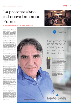
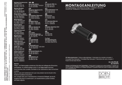
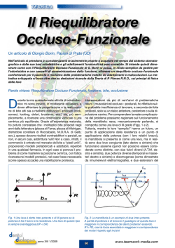
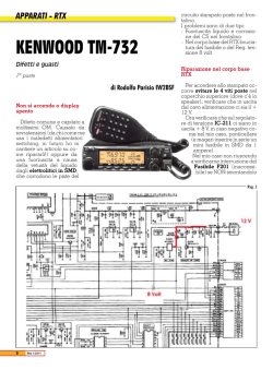
Instruction Manual Manuale di istruzioni VTF Fuzzy Logic Thermoregulator General Information / Informazioni Generali Before using the unit, please read the following instruction manual carefully. Prima dell’utilizzo dello strumento si raccomanda di leggere attentamente il seguente manuale operativo. Do not dispose of this equipment as urban waste, in accordance with EEC directive 2002/96/CE. Non smaltire l’apparecchiatura come rifiuto urbano, secondo quanto previsto dalla Direttiva 2002/96/CE. This unit must be used for laboratory applications only. The manufacturer declines all responsibility for any use of the unit that does not comply with these instructions. Questo strumento deve essere utilizzato solo per applicazioni di laboratorio. La società produttrice declina ogni responsabilità sull’impiego non conforme alle istruzioni degli strumenti. This unit has been designed and manufactured in compliance with the following standards: Lo strumento è stato progettato e costruito in accordo con le seguenti norme: Safety requirements for electrical equipment for measurement, control and for laboratory use IEC/EN 61010-1 Prescrizioni di sicurezza per apparecchi elettrici di misura, controllo e per l’utilizzo in laboratorio UL 61010-1 Electrical equipment for laboratory use CAN/CSA-C22.2 No.61010-1 General requirement - Canadian electrical code Kartell reserves the right to modify the characteristics of its products with the aim to constantly improving their quality. Nell’impegno di migliorare costantemente la qualità dei prodotti, Kartell si riserva la facoltà di variarne le caratteristiche. Contents / Indice 1. 2. 1. 2. 7. 8. 9. 10. 11. INTRODUCTION ........................................................ 2 ASSEMBLY AND INSTALLATION............................. 2 2.1 CONNECTING THE PT100 PROBE............................. 2 2.2 INSTALLING THE VTF .............................................. 2 2.3 USING THE VTF WITH MAGNETIC STIRRERS ............. 2 2.4 OTHER APPLICATIONS............................................. 2 OPERATING CONTROLS ......................................... 3 3.1 SETTING THE WORKING TEMPERATURE .................... 3 3.2 SETTING THE TIMER ................................................ 3 3.3 TEMPERATURE ALIGNMENT ..................................... 4 3.4 UNIT OF MEASURE .................................................. 4 3.5 SAFETY DEVICES AND ERROR SIGNALS .................... 4 START-UP ................................................................. 4 END-OF-WORK OPERATIONS ................................ 4 MAINTENANCE ......................................................... 5 6.1 CLEANING .............................................................. 5 TECHNICAL DATA .................................................... 5 ACCESSORIES ......................................................... 5 SPARE PARTS .......................................................... 5 WIRING DIAGRAM .................................................... 6 WARRANTY ............................................................... 6 7. 8. 9. 10. 11. INTRODUZIONE........................................................ 7 MONTAGGIO ED INSTALLAZIONE ......................... 7 2.1 MONTAGGIO SONDA DI TEMPERATURA PT100 ......... 7 2.2 FISSAGGIO E REGOLAZIONE .................................... 7 2.3 UTILIZZO CON AGITATORI MAGNETICI ....................... 7 2.4 UTILIZZI DIVERSI .................................................... 7 CONTROLLI DI FUNZIONAMENTO ......................... 8 3.1 SELEZIONE DELLA TEMPERATURA DI LAVORO........... 8 3.2 IMPOSTAZIONI TIMER ............................................. 8 3.3 ALLINEAMENTO DELLA TEMPERATURA ..................... 9 3.4 UNITÀ DI MISURA .................................................... 9 3.5 SICUREZZE E SEGNALI DI ERRORE ........................... 9 AVVIO ........................................................................ 9 OPERAZIONI A FINE LAVORO ................................ 9 MANUTENZIONE .................................................... 10 6.1 PULIZIA ............................................................... 10 DATI TECNICI ......................................................... 10 ACCESSORI ............................................................ 10 PARTI DI RICAMBIO ............................................... 10 SCHEMA ELETTRICO ............................................ 11 GARANZIA............................................................... 11 12. DECLARATION OF CONFORMITY 12. DICHIARAZIONE DI CONFORMITA' 3. 4. 5. 6. ............... 6 3. 4. 5. 6. .......... 11 EN 1. Introduction The Thermoregulator is ideal for many applications and meets the most demanding requirements in terms of precision, reliability and flexibility of use thanks to the application of Fuzzy Logic technology. The Fuzzy Logic electronic automatically adapts thermoregulation to the varying factors such as power, load and thermal dispersion specific to each application, by optimizing both overheating and the oscillations around the temperature set-point. The accuracy and precision of thermoregulation at each end the scale and whatever the volume being processed, is a fundamental characteristic of the Vertex. NOTE: the most precise results are obtained when measuring the temperature of aqueous solutions. The microprocessor offers various other functions: • a working time of up to 24 hours and 59 minutes can be set with automatic switch off; • the maximum sample temperatures reached during the test can be recorded. The structure is made of a non-scratch technopolymer resistant to chemical agents and offers a high level of IP54 electrical protection in compliance with regulation CEI EN 60529. The instrument has an in-built safety and control circuit which is constantly active and shuts-down the thermoregulator immediately in the following situations: the temperature probe is not connected; the temperature probe is faulty (cut-off or short-circuited) and/or the temperature is out-of-range. 1 2 3 4 5 6 7 8 9 10 11 Multifunctional display SET DOWN ARROW UP ARROW Unit of measure Timer display on Temperature probe Green “ON” led Clamps Plug Sliding clamp Fig. 1 2. Assembly and installation Check the integrity of the unit after unpacking. The box includes: Thermoregulator complete with: power cable suitable for connection to TK23 heating magnetic stirrer 2.1 Connecting the Pt100 probe Connect the probe to the Thermoregulator as shown on Fig. 2. Pt100 temperature probe Instruction manual - 1 0 . . . + 3 0 0 °C FUZZY LOGIC Set 2.2 Installing the Thermoregulator The thermoregulator has an innovative integrated system to simplify installation on the support rod and facilitate the positioning of the Pt100 probe in the most commonly used containers. The two clamps allow height-regulation whilst a sliding clamp allows horizontal regulation (Fig. 3). VTF D ig it a l T h e r m o r eg u la t o r Fig. 2 Fig. 3 2.3 Using the thermoregulator with magnetic stirrers The power cable is suitable for connection to the most common heating magnetic stirrers with a dedicated socket for the remote control of the heating plate such as the TK23. The socket must supply a tension of between 9 and 16V DC. The integrated installation system allows the instrument to be installed on support rods with a diameter of between 10 and 13 mm. 2.4 Other applications When using the thermoregulator for other applications bear in mind that the transistor output can take a maximum current of 50mA. Where power loads of up to 2200W are required the use of an external power relay is necessary (code A00000001). 2 For the thermoregulation of liquids that are not compatible with the construction material of the probe (stainless steel AISI 316), the use of a glass-coated probe is recommended (code A00000003). In cases in which it is necessary to thermoregulate a liquid that is not in close proximity to the thermoregulator, a 1m probe extension cable is available (code A00000002). 3. Operating controls Install the thermoregulator on the support rod and place the probe in the liquid to be processed. To power it plug the spiral cable into the dedicated socket on the heating magnetic stirrer and turn the stirrer on. The display shows the software version after which it flashes for approx.. 5 seconds showing the last Set Point used (Fig. 4). °C Fig. 4 The current Pt100 probe temperature reading is then displayed on the main window. °C Thermoregulation starts automatically based on the last temperature Set Point used (Fig. 5). Fig. 5 IMPORTANT: the magnetic stirrer always exercises primary control of the heating plate temperature. To control the heating plate temperature using the thermoregulator, set the magnetic stirrer temperature to maximum. The magnetic stirrer temperature control can also be used as a safety thermostat since the heating plate will not exceed the temperature set on the stirrer. In this case a longer heating time will be necessary in order for the sample to reach the set point temperature of the thermoregulator. 3.1 Setting the working temperature From the main window, press the central Set Point Temperature button. The set-up window is displayed (Fig. 4). From -10 to +300 °C Default value: 40 °C With the display flashing use the and keys to select the temperature required. The temperature setting is saved when no keys are touched for approx. 5 seconds (Fig. 5). If no key is pressed for approx. 5 seconds when the set-up window is flashing, the value shown on the display is automatically saved. After 5 seconds the thermoregulator will evaluate the temperature reading of the probe immersed in the liquid and will proceed to thermoregulate the liquid to the temperature selected. NOTE: to display the maximum temperature reached since the instrument was turned on, with the main window displayed keep the turned off. key pressed. The maximum temperature reached is deleted from the memory every time the instrument is 3.2 Setting the timer From the main window press the Working time key twice to display the working time. From 00:00 to 24:59 (h:min.) With the display flashing use the and To switch from hours to minutes press the Default value: 0:00 (Fig. 6) Fig. 6 keys to select the working time required. key once or simply wait 4 seconds (Fig. 7). Fig. 7 With the display flashing use the and keys to select the working time required. The value is saved when no keys are touched for approx. 5 seconds. If no key is pressed for 5 seconds the display returns the main window and the previously displayed value is saved. Count-down starts the moment the working time has been saved. The alternate flashing of the two arrows to the left of the display indicates that the thermoregulator is running in timer-mode (Fig. 8). At the end of the working time the instrument automatically turns off the thermoregulation, and the display shows “End” (Fig. 9). °C Fig. 8 Fig. 9 To return to the main window in order to start new work-cycle, press . The working time will return to the default value of 0:00 and the maximum temperature reached can be viewed by pressing . The working time can be modified when the thermoregulator is in use even if the instrument is running in timer-mode. If the working time is set to 0:00 the instrument will run in continuous mode. 3 NOTE: to display the time left, with the main window displayed keep the key pressed. The time left is automatically reset to zero every time the instrument is turned off. 3.3 Temperature alignment The micro-chip carries out automatic probe calibration therefore a probe calibration procedure is unnecessary. Nevertheless, an offset value of from - 9.9 to + 9.9 °C can be set. Temperature alignment From - 9.9 to + 9.9 °C From - 17 to + 17 °F Turn the instrument on by keeping the and Default value 0.0 °C 0.0 °F keys pressed. °C Use the and keys to modify the “Temperature alignment” parameters (Fig. 10). Fig. 10 If no key is pressed for 5 seconds the display shows the software version and the last set point value. If no key is pressed for a further 5 seconds the display shows the probe temperature reading and saves the value. 3.4 Unit of measure It is possible to select °C or °F. Turn the instrument on by keeping the Use the and and keys pressed. keys to modify the “Unit of measure” (Fig. 11, Fig. 12). If no key is pressed for 5 seconds the display shows the software version and the last set point value. If no key is pressed for a further 5 seconds the display shows the probe temperature reading in the new unit of measure and saves the value. Fig. 11 Fig. 12 3.5 Safety devices and error signals The instrument has an in-built safety and control circuit which is constantly active and shuts-down the thermoregulator immediately in the case of: • unconnected probe • faulty probe (cut-off or short circuited) • temperature out of range (- 10…+300 °C), Thermoregulation stops and the error message “Err” appears on the display. To reset the thermoregulator turn it off and on again after having found and removed the cause of the alarm. 4. Start-up • Install the thermoregulator on the support rod so that the probe is immersed in the liquid by at least 15mm making sure that it does not make contact with the bottom of the container; • Make sure the magnetic stirrer is turned on; • Power the thermoregulator by plugging the spiral cable into the dedicated socket on the heating magnetic stirrer; • Set the magnetic stirrrer temperature to maximum; • Select the temperature and the working time required; • To optimize thermoregulation and improve temperature homogeneity, stir the sample gently but continuously during operation. WARNING • When working with set points near the temperature of evaporation, check that the probe remains immersed in the sample by at least 10mm throughout the work-cycle. • The sample being processed is subject to evaporation and for this reason it may not reach the temperature selected. 5. End-of-work operations To interrupt thermoregulation and leave the thermoregulator thermoregulator powered, turn off heating plate using the knob on the magnetic stirrer. In this way heating stops but the thermoregulator continues to display the temperature. If the timer has been set, the thermoregulator will automatically stop at the end of the set time and the display will show “End”. To reactivate thermoregulation press . 4 At the end of the process, if the thermoregulator is to be left connected to the magnetic stirrer, turn the stirrer off using the mains switch. 6. Maintenance No routine or extraordinary maintenance is necessary apart from periodically cleaning the unit as described in this manual. In compliance with the product guarantee law, repairs to our units must be carried out in our factory, unless previously agreed otherwise with local distributors. 6.1 Cleaning Disconnect the unit from the power supply and use a cloth dampened with a mild, non-flammable detergent. 7. Technical data GENERAL Power supply Absorption Output Size Weight Display Default 9÷15 100 max 50 max 75x145x120 0.250 4 digit LCD Multi function Fuzzy Logic From 10 to 13 5 pole 270° DIN Polypropylene (PP) 0…+50 - 10…+ 60 90% V cc mA mA mm (LxHxD) Kg Type of thermoregulation Support rod Connector Construction material Temperature range Storage temperature range Max. humidity FUNCTIONS Temperature settings Selection interval Resolution Precision Working time settings Continuous mode Time left reading Maximum temperature reached reading mm °C °C % - 10…+ 300 / 14…572 1/1 0.2 / 1 ± 0.5 / ± 0.9 From 0:00 to 24:59 Possible Possible Possible °C / °F °C / °F °C / °F °C / °F h:min PROBE Type of probe Probe speed τ90% Probe length Immersion depth sec mm mm Pt100 5 250 15 minimum SAFETY Probe short-circuit Break in probe circuit Out of temperature range Level of electrical protection Error message and shut-down Error message and shut-down Error message and shut-down IP54 automatic automatic automatic CEI EN60529 8. Accessories A00000001 A00000002 A00000003 A00000004 Derivation element PW10 Probe extension cable, length 1m Glass probe Clamp for the Pt100 probe 9. Spare Parts 40000579 Pt100 probe 40000580 5 Friction assembled 10. Wiring Diagram 11. Warranty The unit is guaranteed against production defects for 25 months from our invoice date. In accordance with this guarantee KARTELL spa undertakes to repair any instruments resulting as faulty due to the quality of the materials used or poor workmanship. Faults arising due to inexpert handling/use or carelessness will not be replaced or repaired under warranty. For more details please contact your Distributor. Exclusions: The warranty will be considered null and void for faults resulting from: inexperience and carelessness of the customer. repairs, maintenance or replacements carried out by unauthorized third parties. use of non-original spare parts. 12. Declaration of conformity We the manufacturer address KARTELL spa Via Delle Industrie, 1 20082 NOVIGLIO (MI) Italy under our responsibility declare that the product is manufactured in conformity with the following standards: EN 61010-1 (2001) EN 61326-1 (2006) 2011/65/EU (RoHS) 2002/96/EC (WEEE) and satisfies the essential requirements of the following directives: Machinery directive 2006/42/EC Low voltage directive 2006/95/EC Electromagnetic compatibility directive 2004/108/EC plus modifications and that the documents listed in annex I are available at our offices as foreseen by the machinery directive. 6 IT 1. Introduzione Il termoregolatore può essere utilizzato in molteplici applicazioni dove sia richiesta precisione, affidabilità e flessibilità di utilizzo, in quanto è dotato di logica Fuzzy. L’elettronica Fuzzy Logic permette di adattare automaticamente la termoregolazione alle differenti situazioni, come potenza, carico e dispersioni termiche, specifiche di ogni applicazione ottimizzando le sovratemperature durante il riscaldamento e le successive oscillazioni intorno alla temperatura impostata. Caratteristica fondamentale del termoregolatore è l’accuratezza e la precisione di termoregolazione su tutta la scala indipendentemente dai volumi in lavorazione. NOTA: le migliori prestazioni di precisione della termoregolazione si ottengono lavorando con soluzioni acquose. Il microprocessore consente di disporre di altre funzioni: • possibilità di selezionare fino a 24 ore e 59 minuti di funzionamento con spegnimento automatico della termoregolazione; • possibilità di registrare la massima temperatura raggiunta dal campione nel corso della prova. Lo struttura è realizzata in tecnopolimero antigraffio e resistente agli agenti chimici con un elevato grado di protezione elettrica IP54 in accordo alle norme CEI EN 60529. Lo strumento è dotato di circuiti di sicurezza e di controllo sempre attivi che riconoscono la non connessione della sonda, la difettosità della sonda (interrotta o in corto circuito) e/o la fuoriuscita della temperatura dall’ambito ammesso, interrompendo istantaneamente la termoregolazione. 1 2 3 4 5 6 7 8 9 10 11 Display multifunzione Tasto SET Tasto FRECCIA GIU’ Tasto FRECCIA SU Unità di misura Visualizzatore di modalità temporizzata attiva Sonda di temperature Pt100 Led di funzionamento verde Sistema di bloccaggio Spina di alimentazione Blocchetto Fig. 1 2. Montaggio ed installazione Verificare l’integrità dello strumento. La scatola contiene: Termoregolatore completo di: cavo di collegamento già predisposto per essere connesso con gli agitatori magnetici TK23 2.1 Montaggio sonda di temperatura Pt100 Collegare la sonda completa di cappuccio di protezione al termoregolatore come da Fig. 2. Sonda di temperatura Pt100 Manuale di istruzioni - 1 0 . . . + 3 0 0 °C FUZZY LOGIC Set VTF D ig it a l T h e r m o r eg u la t o r 2.2 Fissaggio e regolazione VTF è dotato di un innovativo sistema integrato che semplifica il fissaggio sull’asta e facilita il posizionamento della sonda Pt100 all’interno dei più comuni becher. I due morsetti laterali permettono la regolazione in altezza del termoregolatore, mentre il sistema a frizione permette la sua movimentazione sul piano orizzontale (Fig. 3). Fig. 2 Fig. 3 2.3 Utilizzo con agitatori magnetici Il cavo per la connessione elettrica è adatto per il collegamento ai più comuni agitatori magnetici riscaldanti che dispongono di una apposita presa per il comando remoto della piastra riscaldante, come TK23. La presa deve essere in grado di fornire una tensione compresa tra 9 e 15 VDC. Il sistema di fissaggio permette di collocare facilmente lo strumento sulle aste di sostegno aventi diametri compresi tra 10 e 13 mm. 2.4 Utilizzi diversi Per utilizzi diversi tenere presente che l’uscita del comando a transistor (Output) supporta correnti massime di 50 mA. 7 Nel caso in cui si debbano pilotare carichi fino a 2200 W di potenza è necessario utilizzare degli appropriati relè di potenza esterni (cod. A00000001). Per la termoregolazione di liquidi non compatibili con il materiale con cui è stata realizzata la sonda (acciaio inossidabile Aisi 316) in dotazione con il termoregolatore, è consigliabile l’utilizzo della sonda con copertura in vetro (cod. A00000003). Nel caso in cui si ha la necessità di termoregolare un liquido lontano dal termoregolatore è disponibile un cavo di 1 m di lunghezza (cod. A00000002). 3. Controlli di funzionamento Collocare lo strumento sull’apposita asta di sostegno inserendo la sonda nel liquido in lavorazione. Per alimentare il termoregolatore è necessario accendere l’agitatore magnetico riscaldante dopo aver inserito la spina del cavo spiralato nell’apposita presa. All’accensione dello strumento visualizza la versione software e successivamente il display lampeggia approssimativamente per 5 secondi visualizzando l’ultimo Set Point utilizzato (Fig. 4). In seguito, il display visualizza la finestra principale mostrando la temperatura letta dalla sonda Pt100. La termoregolazione si attiva automaticamente alla temperatura dell’ultimo Set Point utilizzato (Fig. 5). °C Fig. 4 °C Fig. 5 NOTA: l’agitatore magnetico esercita sempre il controllo primario della temperatura sulla piastra. Per rendere operativo il riscaldamento della piastra da parte del termoregolatore, è necessario selezionare la massima temperatura sull’agitatore magnetico. Il controllo di temperatura della piastra sull’agitatore magnetico può essere utilizzato anche come termostato di sicurezza. In questo caso la piastra non supererà la temperatura impostata sull’agitatore magnetico, implicando un tempo più lungo nel raggiungimento della temperatura di Set Point. 3.1 Selezione della temperatura di lavoro Dalla finestra principale, premendo una volta il tasto centrale Temperatura di Set Point si accede alla finestra di impostazione (Fig. 4). Da -10 to +300 °C Valore di default: 40 °C Con i tasti e , durante la fase di visualizzazione intermittente, è possibile selezionare il valore di temperatura desiderato, che verrà memorizzato automaticamente dopo circa 5’’ (Fig. 5). Al contrario, se non si preme nessun tasto durante la fase di visualizzazione intermittente, lo strumento terrà in memoria il valore che appare ad intermittenza sul display. Dopo 5’’ visualizzerà la temperatura letta in quel momento dalla sonda immersa nel liquido e termoregolerà il liquido alla temperatura impostata. NOTA: dalla finestra principale, tenendo premuto il tasto è possibile visualizzare la massima temperatura raggiunta dopo l’ultima accensione. La massima temperatura raggiunta viene cancellata dalla memoria allo spegnimento dell’unità. 3.2 Impostazioni Timer Premendo due volte il tasto Tempo di azionamento dalla finestra principale si visualizza il tempo di azionamento da 00:00 a 24:59 (h:min.) Valore di default: 0:00 (Fig. 6) Fig. 6 Con i tasti e durante la fase di visualizzazione intermittente, è possibile programmare le ore del tempo di azionamento. Per passare da ore a minuti premere una volta il tasto o aspettare 4 secondi (Fig. 7). Fig. 7 Con i tasti e durante la fase di visualizzazione intermittente, è possibile programmare il valore in minuti del tempo di azionamento che verrà memorizzato automaticamente dopo circa 5 sec. Se non si preme nessun tasto dopo 5 secondi il display torna a visualizzare la finestra principale tenendo in memoria il valore precedentemente visualizzato. Il conteggio del tempo ha inizio immediato, cioè da quando viene memorizzato il valore. Lo stato di modalità temporizzata è intuibile con il lampeggio alternato delle 2 frecce (Fig. 8). Allo scadere del tempo di azionamento lo strumento provvederà allo spegnimento automatico della termoregolazione, visualizzando sul display la scritta “End” permanente. (Fig. 9). °C Fig. 8 Fig. 9 Per uscire da questo stato, per una nuova lavorazione, è necessario premere il tasto . In questo modo il tempo di azionamento si posizionerà nuovamente sul valore di default (0:00) e sarà possibile visualizzare la temperatura massima raggiunta premendo il tasto . 8 Durante il funzionamento, è possibile modificare il tempo di azionamento anche se è già stato programmato. Se il tempo di azionamento è 0:00 lo strumento non eseguirà nessun conteggio del tempo ed il funzionamento sarà quindi infinito. NOTA: dalla finestra principale, tenendo premuto il tasto è possibile visualizzare, se impostato, il tempo residuo. L’azzeramento del tempo residuo avviene automaticamente ogni volta che si spegne lo strumento. 3.3 Allineamento della temperatura Il microprocessore esegue l’autocalibrazione della sonda Pt100, di conseguenza non è necessaria una procedura di calibrazione della stessa. Tuttavia è possibile inserire un offset al valore visualizzato compreso tra - 9.9 e + 9.9 °C. Allineamento temperatura da - 9.9 to + 9.9 °C Valore di default 0.0 °C da - 17 to + 17 °F 0.0 °F Tenere premuti contemporaneamente i tasti , per accedere alla relativa finestra. °C Con i tasti e , è possibile variare il parametro “Allineamento temperatura” (Fig. 10). Fig. 10 Se non si preme nessun tasto dopo 5 secondi il display torna a visualizzare la versione software, l’ultimo Set Point e dopo altri 5 secondi la temperatura letta dalla sonda memorizzando il valore. 3.4 Unità di misura E’ possibile selezionare l’unità di misura scegliendo tra °C e °F. Tenere premuti contemporaneamente i tasti Con i tasti e , per accedere alla relativa finestra. , è possibile variare il parametro “Unità di misura” (Fig. 11, Fig. 12). Se non si preme nessun tasto dopo 5 secondi il display torna a visualizzare la versione software, l’ultimo Set Point e dopo altri 5 secondi la temperatura letta dalla sonda nella nuova unità di misura. Fig. 11 Fig. 12 3.5 Sicurezze e segnali di errore Lo strumento è dotato di circuiti di sicurezza e di controllo sempre attivi che riconoscono: • sonda non connessa • sonda difettosa (interrotta o in corto circuito), • fuoriuscita della temperatura dall’ambito ammesso (-10…+300 °C), interrompendo istantaneamente la termoregolazione e visualizzando sul display la scritta “Err”. Il ripristino del normale funzionamento avviene spegnendo e riaccendendo lo strumento dopo aver rimosso la causa d’allarme. 4. Avvio • Collocare lo strumento sull’apposita asta di sostegno ad una altezza tale che la sonda sia immersa nel liquido per almeno 15 mm e non sia a contatto con il fondo del recipiente; • Assicurarsi che l’agitatore magnetico sia acceso; • Alimentare il termoregolatore inserendo la spina posta sul cavo, nella presa dell’agitatore magnetico riscaldante; • Impostare al massimo la temperatura dell’agitatore magnetico; • Selezionare la temperatura desiderata e l’eventuale tempo di azionamento; • Per ottenere una migliore termoregolazione ed omogeneità di temperatura è consigliabile mantenere una leggera agitazione del liquido in lavorazione. ATTENZIONE • Se si lavora con Set Point prossimi alla temperatura di evaporazione del liquido, occorre accertarsi che la sonda rimanga sempre immersa nel liquido per almeno 10 mm durante il ciclo di lavoro, in modo da controllare la temperatura del liquido. • Normalmente il liquido in lavorazione subisce evaporazione che può causare il non raggiungimento della temperatura impostata da parte del liquido in lavorazione. 5. Operazioni a fine lavoro Per interrompere la termoregolazione e lasciare alimentato il termoregolatore termoregolatore, è sufficiente spegnere il riscaldamento della piastra mediante l’apposito attuatore (manopola) sull’agitatore magnetico. In questo caso il riscaldamento si arresterà ma il termoregolatore continuerà a visualizzare la temperatura. Nel caso si programmi un tempo di azionamento, allo scadere dello stesso il termoregolatore arresterà automaticamente la termoregolazione visualizzando la scritta End. In questo caso per riattivare la termoregolazione è necessario premere il tasto 9 . A fine lavoro, nel caso si lasci collegato il termoregolatore all’agitatore magnetico, spegnere quest’ultimo mediante l’interruttore generale. 6. Manutenzione La manutenzione ordinaria e straordinaria non è prevista salvo la pulizia periodica dello strumento come descritto in questo manuale. In conformità alla legge sulla garanzia dei prodotti, le riparazioni dei nostri strumenti devono essere eseguite presso la nostra sede, salvo accordi diversi con i distributori locali. 6.1 Pulizia La pulizia dello strumento deve essere eseguita, dopo aver staccato l’alimentazione, con un panno inumidito con detergenti non infiammabili e non aggressivi. 7. Dati tecnici GENERALI Alimentazione Assorbimento Uscita Dimensioni Peso Display Default 9÷15 100 max 50 max 75x145x120 0,250 LCD a 4 digits multi funzione Fuzzy Logic Da 10 a 13 DIN 5 poli 270° Tecnopolimero 0…+ 50 - 10…+ 60 Max 90 V dc mA mA mm (BxHxP) Kg Tipo di termoregolazione Fissaggio Connettore Materiale di costruzione Temperatura ambiente ammessa Temperatura di stoccaggio ammessa Umidità ammessa mm °C °C % FUNZIONI Temperature selezionabili °C / °F Selezione °C / °F Risoluzione °C / °F Precisione °C / °F Tempi di funzionamento selezionabili h:min Funzionamento in continuo Visualizzazione del tempo residuo Visualizzazione temperatura massima raggiunta - 10…+ 300 / 14…572 1/1 0,2 / 1 ± 0,5 / ± 0,9 Da 0:00 a 24:59 Possibile Possibile Possibile SONDA Tipo di sonda Velocità della sonda τ90% Lunghezza della sonda Altezza di immersione della sonda Pt100 5 250 15 minimo SICUREZZE Sonda in corto Sonda interrotta Fuori ambito di temperatura Grado di protezione elettrica sec mm mm Visualizzazione a display con spegnimento Visualizzazione a display con spegnimento Visualizzazione a display con spegnimento IP54 automatico automatico automatico CEI EN60529 8. Accessori A00000001 A00000002 A00000003 A00000004 Elemento di derivazione PW10 Cavo di prolunga sonda, 1 m Sonda in vetro Pinza per sonda 9. Parti di ricambio 40000579 Sonda di temperatura Pt100 40000580 10 Frizione assemblata 10. Schema elettrico 11. Garanzia L’unità è coperta da garanzia contro difetti di produzione per 25 mesi a partire dalla data di fatturazione VELP. In virtù di tale garanzia KARTELL spa si impegna a riparare lo strumento che risulti difettoso per qualità del materiale o cattiva lavorazione. Non verranno sostituiti o riparati in garanzia gli strumenti resi difettosi da imperizia ed incuria. Per ulteriori dettagli contattare il proprio Distributore. Esclusioni: La garanzia decade per difetti risultanti da: imperizia e incuria da parte dell’operatore riparazioni, manutenzioni o sostituzioni fatte da personale o Aziende non autorizzate dalla casa costruttrice uso dello strumento che non sia in conformità con le istruzioni/raccomandazioni date nel presente manuale uso di ricambi non originali. 12. Dichiarazione di conformita' Noi casa costruttrice indirizzo KARTELL spa Via Delle Industrie, 1 20082 NOVIGLIO (MI) Italy Dichiariamo sotto la ns. responsabilità che il prodotto è conforme alle seguenti norme: EN 61010-1 (2001) EN 61326-1 (2006) 2011/65/UE (RoHS) 2002/96/CE (RAEE) E soddisfa i requisiti essenziali delle direttive: Macchine 2006/42/CE Bassa tensione 2006/95/CE Compatibilità elettromagnetica 2004/108/CE Più successive modifiche e che sono presenti presso la ns. sede i documenti richiesti nell'allegato I della direttiva macchine. 11 10001362/A3 12
© Copyright 2026 Paperzz