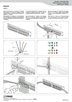
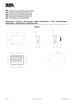
H
C
T
I
W
S
L
F
4
5
6
7
8
Conexión de la tensión de
alimentación/contacto de aviso/FE
El módulo también está en capacidad de
funcionar con sólo una tensión de
alimentación (sin puenteo a otros bornes
de tensión de alimentación) y/o sin
conexión del contacto de aviso.
Si no se da un suministro de tensión
redundante, el conmutador indica el corte
de una tensión de alimentación a través del
contacto de aviso. Puede evitarse esta
indicación de error, al conducir la tensión
de alimentación en paralelo a los dos
bornes, como se muestra en la Figura 3.
Conexión redundante de la tensión de
alimentación
H
C
T
I
W
S
L
F
M
S
X
F
2
/
X
T
4
H
C
T
I
W
S
Pour de plus amples informations techniques, voir la fiche technique spécifique au
module et le manuel d'utilisation sous www.download.phoenixcontact.fr.
1 Alimentation/borne de sign./FE
4 Adresse MAC
2 Interface de communication V.24 5 Ethernet ports
3 Raccordement terre de
6 Voyants de diagnostic et d'état
fonctionnement
AUTOMATIONWORX
FL SWITCH LM 8TX
FL SWITCH LM 4TX/2FX
FL SWITCH LM 4TX/2FX SM
DE
EN
FR
IT
ES
Art.-Nr. 2832632
Art.-Nr. 2832658
Art.-Nr. 2891916
Einbauanweisung für den Elektroinstallateur
Installation notes for electrical personnel
Instruction d’installation pour l’électricien
Istruzioni di installazione per l’elettricista
Instrucción de montaje para el ingeniero eléctrico
2
1
L
F
Wire Range AWG 30-12 30-12 30-12
Torque (Lbs-Ins) 5-7
5-7
5-7
Voltage
24 V dc 24 V dc 24 V dc
Current
170 mA 250 mA 250 mA
“The
MINI DIN
is forconnect,
temporary
connection
only.connector
Dothenotarea
use,
disconnect
unless
is known toorbeinnonhazardous.
Connection
or
disconnection
an
explosive
explosion.”atmosphere could result in an
Ethernet switch a 6(8) porte 10/100 MBit/s
Avvertenze sulla sicurezza e sui pericoli
Nel maneggiare elementi che possono accumulare cariche
elettrostatiche, attenersi alle necessarie misure di sicurezza
(EN 61340-5-1 e EN 61340-5-2, nonché IEC 61340-5-1 e
IEC 61340-5-2)!
Il modulo FL SWITCH LM ... è concepito esclusivamente per il funzionamento con basse tensioni di sicurezza (SELV) secondo IEC 950 /
EN 60950 / VDE 0805.
6
3
5
Per ulteriori informazioni consultare la scheda tecnica specifica del modulo e il
manuale per l'utente alla pagina www.download.phoenixcontact.it..
1 Alimentazione/contatto spia/FE
4 Indirizzo MAC
2 Interfaccia di comunicazione V.24 5 Porte Ethernet
3 Connessione FE
6 LED di stato e di diagnosi
Interfaz de comunicación V.24
Deben ajustarse los siguientes parámetros
de transmisión:
Bits por segundo
38400
Bits de datos
8
Paridad
ninguna
Bits de parada
1
Control de flujo
ninguno
Asignación del conector hembra RJ45
Pin 1
RD+
Pin 2
RDPin 3
TD+
Pin 4
TDPin 4, 5, 7 y 8
sin uso
asignado
Observer les mesures de précaution nécessaires lors du maniement
des composants sensibles aux décharges électrostatiques
(EN 61340-5-1 et EN 61340-5-2 ainsi que selon CEI 61340-5-1 et
CEI 61340-5-2) !
Le module FL SWITCH LM ... est uniquement réglé pour être utilisé
avec une très basse tension de sécurité (SELV) d'après CEI 950 /
EN 60950 / VDE 0805.
Conmutador Ethernet de 6(8) puertos 10/100 MBit/s
Indicaciones y advertencias de seguridad
Conexión de los conectores RJ45/SC
Teniendo en cuenta la codificación,
conecte el conector macho RJ45/SC al
conector hembra hasta que encaje.
Desmontaje de los conectores RJ45
Empuje la pestaña de encaje en dirección
al conector (A) y retire seguidamente el
conector (B).
Desmontaje de los conectores SC
Rimuovere con cautela il connettore SC
dalla presa afferrandolo per la sua sede e
facendo attenzione a non danneggiare il
cavo in fibra ottica.
Observe las medidas preventivas necesarias al manipular elementos
expuestos a peligro de descarga electrostática (EN 61340-5-1 y
EN 61340-5-2 así como IEC 61340-5-1 y IEC 61340-5-2).
El módulo FL SWITCH LM ... está diseñado exclusivamente para el funcionamiento con tensión extra-baja de seguridad (SELV) según CEI 950
/ EN 60950 / VDE 0805.
Encontrará Vd. más informaciones técnicas en la hoja de características
específicas del módulo y en el manual de usuario en
www.download.phoenixcontact.es.
1 Alimentación/contacto de aviso/FE 4 Dirección MAC
2 Interfaz de comunicación V.24
5 Puertos Ethernet
3 Conexión FE (tierra funcional)
6 Indicaciones de diagnóstico y estado
00.A0.45
.2E.75.
12
00.A0.45
.23.A5.
22
4
10/100 MBit/s Switch mit sechs oder acht Ports
Sicherheits- und Warnhinweise
Beachten Sie die notwendigen Vorsichtsmaßnahmen bei der
Handhabung elektrostatisch gefährdeter Bauelemente (EN 61340-5-1
und EN 61340-5-2)!
Das Modul FL SWITCH LM... ist ausschließlich für den Betrieb mit
Sicherheitskleinspannung (SELV) nach IEC 950 / EN 60950 ausgelegt.
Weiterführende technische Informationen finden Sie im spezifischen Datenblatt
und im Anwenderhandbuch unter www.download.phoenixcontact.de.
1 Versorgung/Meldekontakt/FE
4 MAC-Adresse
2 V.24-Kommunikationsschnittstelle 5 Ethernet-Ports
3 FE-Kontakt
6 Diagnose- und Status-Anzeigen
10/100 MBit/s Switch with six or eight ports
Sicherheits- und Warnhinweise
English
3
X
F
2
/
X
T
4
Consignes de sécurité et avertissements
Deutsch
X
T
8
PHOENIX CONTACT GmbH & Co. KG
32823 Blomberg, Germany
Phone
+49-(0)5235-3-00
Fax
+49-(0)5235-3-4 1200
www.phoenixcontact.com
Commutateur Ethernet 6(8) ports 10/100 MBit/s
Français
2
Montaje
Coloque el módulo desde arriba con la
ranura sobre el carril portante. Presione el
módulo en la parte frontal en dirección a la
superficie de montaje hasta escuchar que
encaja.
Desmontaje
Use una herramienta adecuada para asir
en el anclaje de la sujeción y tire de él
hacia abajo, presionando para ello la
herramienta (A) hacia arriba. Retire del
carril el borde inferior (B) y luego el
módulo.
A These devices are intended to be installed
within an enclosure rated at least IP54.
B Cl. I, Zn. 2, AEx nC IIC T4 and Ex nC IIC T4
X
Amb. temp. range : -40°C < T amb < +70°C
Temperature Class T4
Nature of Supply:
C
Español
1
UL notes/directives
Italiano
Español
DE
EN
FR
IT
ES
Technische Änderungen vorbehalten!
Technical modifications reserved!
Toutes modifications techniques réservées !
Con riserva di modifiche tecniche!
¡Reservado el derecho a las modificaciones técnicas!
© PHOENIX CONTACT 11/2012
MNR 9027539 - 01
731701
Observe the necessary safety precautions when handling components
that are vulnerable to electrostatic discharge (EN 61340-5-1 and
EN 61340-5-2, as well as IEC 61340-5-1 and IEC 61340-5-2)!
The FL SWITCH LM ... module was designed only for use with SELV in
accordance with IEC 950 / EN 60950 / VDE 0805.
Further technical information can be found in the specific data sheet and in the
user manual at www.download.phoenixcontact.com.
4 MAC address
5 Ethernet ports
6 Status and diagnostic indicators
1 Supply voltage/alarm contact/FE
2 V.24 communication interface
3 FE connection
Deutsch
1
1
2
A
Anschluss Versorgung, Meldekontakt,
FE
Das Modul ist auch mit nur einer
Versorgungsspannung (ohne Brückung
auf die anderen Versorgungsspannungsklemmen) und/oder ohne Beschaltung des
Meldekontakts voll funktionsfähig.
Bei nicht redundanter Spannungszuführung meldet der Switch über den Meldekontakt den Ausfall einer Versorgungsspannung. Sie können diese Fehlermeldung verhindern, indem Sie, wie in Bild 3
dargestellt, die Versorgungsspannung
parallel auf beide Klemmen führen.
Redundanter Anschluss der
Versorgungsspannung
3
5
V.24-Kommunikationsschnittstelle
Folgende Übertragungsparameter sind
einzustellen:
Bits pro Sekunde
38400
Datenbits
8
Parität
Keine
Stoppbits
1
Flusssteuerung
Kein
5
V.24 communication interface
The following transmission parameters
have to be set:
Bits per second
38400
Data bits
8
Parity
None
Stop bits
1
Flow control
None
6
Belegung der RJ45-Buchse
Pin 1
RD+
Pin 2
RDPin 3
TD+
Pin 4
TDPin 4, 5, 7 und 8
nicht benutzt
6
7
Anschluss der RJ45/SC-Stecker
Stecken Sie den RJ45/SC-Stecker unter
Beachtung der Codierung in die Buchse
bis er einrastet.
Entfernen der RJ45-Stecker
Drücken Sie die Rastnase in Richtung des
Steckers (A) und ziehen Sie dann den
Stecker ab (B).
Entfernen der SC-Stecker
Ziehen Sie den SC-Stecker vorsichtig aus
der Buchse ohne die LWL-Leitung zu
beschädigen.
7
2
B
B
3
1
C
A
4
1
OUT
3
2
OUT
opt.
opt.
24 V DC
24 V DC
US1
US1
5
6
n .c . P in 8
V .2 4
C T S
6
4
2
T D - P in 6
re s .
n .c . P in 4
1
R x D
T D +
P in 3
R D - P in 2
T x D
R D +
7
R J 4 5
n .c . P in 5
3
4
n .c . P in 7
R T S
5
1
US 2
US
A
1
US
2
US
1
US
2
US
ig
it a
1
B
5
5
4T
H LM 8
ITC 3265
SW .28
FL No
d.Or
4T
LM0
81
731701
X/2F
X
2
4
Français
Installation
Place the module on the DIN rail from
above using the slot. Push the front of the
module toward the mounting surface until it
audibly snaps into place.
Removal
Insert a suitable tool into the latch of the
holding clamp and pull the latch downward
by pushing the tool upward (A). Pull out the
lower edge (B) and then remove the
module from the DIN rail.
1
Connecting the supply
voltage / alarm contact / FE
The module can function even with only
one supply voltage (without a bridge to the
other supply voltage terminal) and/or
without wiring to the alarm contact.In the
case of non-redundant voltage flow, the
switch reports one supply voltage failure
via the alarm contact. You can prevent this
error message by connecting the supply
voltage to both terminals in parallel, as
illustrated in figure 3.
Redundant supply voltage connection
3
Italiano
Montage
Placer le module par le haut avec la rainure
sur le profilé. Appuyer sur la partie avant du
module en direction de la surface de
montage jusqu'à ce qu'il s'encliquette de
façon audible.
Démontage
Introduire un outil adéquat dans la barrette
de retenue et la pousser vers le bas en
appuyant sur l'outil (A). Retirer la bordure
inférieure (B), puis le module du profilé.
1
Raccordement tension
d’alim./borne de sign./FE
Le module fonctionne également avec une
seule tension d'alimentation (sans pontage
sur les autres bornes) et/ou sans câblage
de la borne de signalisation.
En cas d'alimentation en tension non
redondante, le commutateur indique le
défaut d'une tension d'alimentation par
l'intermédiaire de la borne de signalisation.
L’apparition de ce message d'erreur peut
être évitée en dirigeant la tension
d'alimentation parallèlement sur les deux
bornes, comme indiqué dans la figure 3.
Raccordement redondant de la tension
d'alimentation
3
5
Interface de communication V.24
Les paramètres de transmission suivants
doivent être configurés :
Bits par seconde
38400
Bits de données
8
Parité
Aucune
Bits d'arrêt
1
Contrôle du flux
Aucun
5
Interfaccia di comunicazione V.24
Impostare i seguenti parametri di
trasmissione:
Bit al secondo
38400
Bit dati
8
Parità
Nessuna
Bit stop
1
Controllo del flusso
Nessuno
Assignment of the RJ45 female
connector
Pin 1
RD+
Pin 2
RDPin 3
TD+
Pin 4
TDPin 4, 5, 7 and 8
not used
6
Affectation du connecteur femelle RJ45
Broche 1
RD+
Broche 2
RDBroche 3
TD+
Broche 4
TDBroches 4, 5, 7 et 8
vacantes
6
Assegnamento del connettore femmina
RJ45
Pin 1
RD+
Pin 2
RDPin 3
TD+
Pin 4
TDPin 4, 5, 7 e 8
non utilizzati
Connecting the RJ45/SC connector
Connect the RJ45/SC male connector to
the female connector according to the
encoding until it snaps into place.
Removing the RJ45 connector
Push the latch toward the connector (A)
and then remove the connector (B).
Removing the SC connector
Carefully hold the SC connector by its
housing and pull it out of the socket without
damaging the optical fiber.
7
Raccordement des connecteurs mâles
RJ45/SC
Brancher le connecteur mâle RJ45/SC
dans le connecteur femelle en respectant
le codage, jusqu'à encliquetage.
Retrait des connecteurs RJ45
Presser l'ergot d'encliquetage en direction
du connecteur (A) et retirer ensuite le
connecteur (B).
Retrait des connecteurs SC
Retirer précautionneusement le
connecteur SC du connecteur femelle par
son boîtier en prenant garde à ne pas
endommager le câble de fibre optique.
7
Collegamento dei connettori maschio
RJ45/SC
Tenendo conto delle codificazioni, inserire
il connettore maschio RJ45/SC nel
connettore femmina, finché non si incastra.
Rimozione dei connettori maschio RJ45
Spingere la linguetta in direzione del
connettore maschio (A) e
successivamente rimuovere il connettore
(B).
Rimozione dei connettori maschio SC
Rimuovere con cautela il connettore SC
dalla presa afferrandolo per la sua sede e
facendo attenzione a non danneggiare il
cavo in fibra ottica.
2
4
2
4
Montaggio
Inserire il modulo dall'alto con la
scanalatura sulla guida di montaggio.
Premere il modulo sulla parte frontale in
direzione della superficie di montaggio fino
a sentire il rumore dell'incastro.
Smontaggio
Inserire un utensile adatto nell'apertura del
dispositivo di fissaggio e tirare verso il
basso, premendo l'utensile verso l'alto (A).
Estrarre dalla guida di montaggio il bordo
inferiore (B) e quindi il modulo.
Connessione tensione di
alimentazione/contatto spia/FE
Il modulo è completamente funzionante
anche con solo una tensione di
alimentazione (senza ponticellamento
degli altri morsetti della tensione di
alimentazione) e/o senza cablaggio del
contatto spia.
In caso di alimentazione di tensione non
ridondante, lo switch comunica tramite il
contatto spia la mancanza di una tensione
di alimentazione. È possibile impedire
questo messaggio di errore alimentando
parallelamente la tensione di
alimentazione su entrambi i morsetti, come
mostrato in figura 3.
Collegamento ridondante della tensione
di alimentazione
P in 1
8
ITCH32
SW
FL No.28
d.Or
English
Montage
Setzen Sie das Modul von oben mit der Nut
auf die Tragschiene. Drücken Sie das
Modul an der Front in Richtung der
Montagefläche bis es hörbar einrastet.
Demontage
Fassen Sie mit einem geeignetem
Werkzeug in die Lasche der Haltespange
und ziehen Sie die Lasche nach unten,
indem Sie das Werkzeug nach oben
drücken (A). Ziehen Sie die Unterkante (B)
und dann das Modul von der Tragschiene
weg.
X/2
FX
l Inp
8
8
8
8
© Copyright 2026 Paperzz