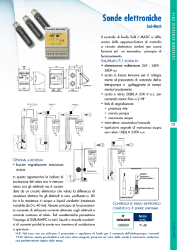
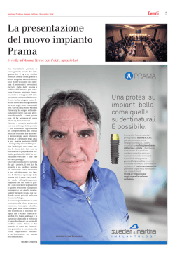
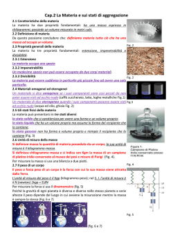
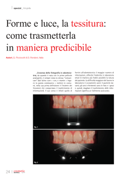
Scheda tecnica Sonde UHS
UHS probes Data Sheet
S.r.l.
Sede legale/Headquarters: Via Montorio 108, 37131 Verona (Italy)
Sede amministrativa e commerciale/Administrative and commercial division:
Via Marco Biagi 27,
37019 Peschiera del Garda (VR)
P.Iva/VAT number: 04181340235
E-mail: [email protected] - www.gnrg.it
INDICE / TABLE OF CONTENTS
► Presentazione
Presentation . . . . . . . . . . . . . . . . . . . . . . . . . . . . . . . . . . . . . . . . . . . . . . 2
► Principi alla base del geotermico UHS
Guiding principles for UHS geothermal plants . . . . . . . . . . . . . . . . . . 3
► Funzionamento
Working principles . . . . . . . . . . . . . . . . . . . . . . . . . . . . . . . . . . . . . . . . . 4
► Sonde UHS
UHS probes . . . . . . . . . . . . . . . . . . . . . . . . . . . . . . . . . . . . . . . . . . . . . . . 6
► Specifiche sonda UHS
Technical specifications . . . . . . . . . . . . . . . . . . . . . . . . . . . . . . . . . . . . 8
► Fase di progettazione
Planning phase. . . . . . . . . . . . . . . . . . . . . . . . . . . . . . . . . . . . . . . . . . . . 9
► Installazione
Installation. . . . . . . . . . . . . . . . . . . . . . . . . . . . . . . . . . . . . . . . . . . . . . . 10
1. Imballo
The packaging. . . . . . . . . . . . . . . . . . . . . . . . . . . . . . . . . . . . . . . 10
2. Montaggio e posa delle sonde UHS
Installation and setup of UHS probes. . . . . . . . . . . . . . . . . . . . . 11
1
► Presentazione
► Product
L’Underground Heat Sink (UHS) è un innovativo sistema
di sonde geotermiche per impianti geotermici a bassa
entalpia (geotermico di superficie) capaci di offrire
in un’unica soluzione il condizionamento e il riscaldamento degli ambienti collegati.
Il geotermico con sonde UHS si basa su una nuova
soluzione (domanda di brevetto n. BO2012A000637)
che permette di ridurre del 50-80% i costi energetici
rispetto alle tradizionali tecnologie come caldaie a
gas, boiler elettrici e pompe elettriche con colonna di
raffreddamento ad aria.
Le sonde UHS si distinguono infatti da quelle tradizionali
per la loro forma a spirale multipla e per la rivoluzionaria doppia interfaccia di scambio, parte in plastica
e parte in acciaio che conferisce loro compattezza,
agilità d’installazione e facile manutenzione, nonché un’interazione con il
terreno dalle 5 alle 7 volte superiore
alle sonde classiche. Da qui la loro
alta efficienza.
Questo sistema prevede l’accoppiamento delle sonde UHS a pompe
termiche elettriche o a gas metano
realizzando in un’unica soluzione un
sistema di riscaldamento e condizionamento pienamente regolabile ed
in grado di mantenere performance
molto elevate anche nelle stagioni
più calde e più fredde.
Il geotermico UHS può costituire
anche impianti ibridi in quanto
perfettamente accoppiabile agli
impianti tradizionali (caldaie a gas,
boiler elettrici, impianti di condizionamento esistenti), poiché utilizzano
acqua non glicolata come unico
vettore termico. Allo stesso modo
possono utilizzare come scambiatori per il ciclo di riscaldamento e
condizionamento, termoventilanti e
impianti a pavimento/parete e split,
non richiedendo così interventi di
sostituzione degli impianti esistenti.
Fattibilità: il geotermico UHS può essere facilmente installato in qualsiasi
edificio residenziale, commerciale o
industriale nuovo o esistente. Nel
caso di edifici esistenti, il sistema
UHS abbinato alle pompe termiche
può essere facilmente accoppiato
ad impianti già esistenti (split, termoventilanti e anche per l’acqua
calda sanitaria). Inoltre il sistema UHS
può essere abbinato con maggiore
efficienza ad impianti di condizionamento ad acqua calda (solar
cooling). È possibile installarlo in quasi tutti i tipi di terreno e prevede costi
e tempi d’installazione ottimali.
2
Presentation
The Underground Heat Sink (UHS) is an innovative
low enthalpy geothermal probe system (near-surface
geothermal system) that gives the chance to set one
single solution both for the heating and for the cooling
of the connected building.
Geothermal plants with UHS probes are based on a
new concept of geothermal probes (patent pending
n. BO2012A000637) cutting costs by 50-80% in comparison with the traditional technologies (gas and electric
boilers, electric pumps with air-cooled cooling pipe).
In comparison with traditional ones, these UHS probes
stand out for their multiple helical form and the
trailblazing double exchange interface part of plastic
and part of steel.
This characteristic grants compactness, installation and
maintenance handiness and from
5 to 7 times superior interaction capability with the soil in
comparison with traditional
probes. This is the secret of
their high efficiency.
The UHS system is coupled with
electric or natural gas pumps
that are joined with the geothermal probes in order to obtain
an AC system that is able to
maintain fully verifiable high
performances even during the
hottest/coldest parts of the
seasonal cycle.
Furthermore it uses only water
(not added with glycols) as
thermal carrier and thus there
is the chance to built hybrid
systems, matched with already
existing, traditional systems (such
as gas and electric boilers,
existing AC). Even the existing
fan heaters, underfloor/wall
heating systems and splits can
be easily used as heat exchangers.
Fig. 1 - Sezione di Sonda UHS
con pozzo incamiciato
Fig. 1 - UHS probe section in the
jacketed pit
Feasibility: the UHS system can
be installed in every residential,
commercial,
and
industrial building, both existing or
new. In the case of already
existing buildings, the UHS
system (coupled with a heat
pump) can be matched to the
existing boilers, fan heaters, AC
systems and it can even supply
hot water. Moreover, the UHS
system can be coupled with
“solar cooling” systems in order
to enhance their efficiency.
It is suitable for almost every
kind of soil and it needs short
installation times and low costs.
► Principi
alla base del
geotermico UHS
► Guiding
Principles
for UHS geothermal plants
Le sonde UHS sono state studiate per trarre il massimo
beneficio dalle leggi naturali che regolano gli scambi
termici. In particolar modo si è cercato di:
UHS probes have been conceived in order to benefit as
much as possible from the natural principles governing
heat transfer. They specifically takes advantage of:
1. UTILIZZARE L’ANTICICLICITA’ TRA TEMPERATURA DEL
TERRENO E TEMPERATURA ATMOSFERICA
1. THE ANTI-CYCLICAL TURN BETWEEN ATMOSPHERIC
AND SOIL TEMPERATURE
La tecnologia di regolazione geotermica UHS sfrutta la
The UHS thermal regulation technology uses the soil
temperatura sotterranea tra i 3 ed
temperature between 3 and 48
i 48 m di profondità, caratterizzata
m / 10 and 157 ft that is cyclically
da un ciclo termico stagionale
inverted in respect with the
inverso rispetto a quello atmosfeatmospheric temperature during
rico: più caldo durante l’inverno
the seasonal cycle. In fact the soil
e più fresco durante l’estate.
is colder in summer and warmer
Tuttavia quest’alternanza si gioca
in winter. However this cyclical
su minime e non su sensibili vaantithesis plays on very small
riazioni di temperatura. A basse
temperature differences during
profondità, infatti, la temperatura
the year since soil keeps its rates
del terreno si mantiene tra i 7° C
between 7° and 12.5° C / 44.6 °F
e i 12,5° C durante l’anno. Per
and 53.6 °F.
intercettare delle variazioni così
To
intercept
such
small
piccole serve una tecnologia che
differences
an
appropriate
garantisca un’elevata velocità di
technology is needed, granting
scambio termico con il terreno
a high heat transfer rate with
come quella delle sonde UHS.
the soil. UHS probes meet
Infatti è stato testato che, grazie
this requirement since their
alla loro innovativa geometria
innovative geometrical form and
Fig. 2/3 - Andamento della
e alla scelta dei materiali utiliztheir carefully selected materials
temperatura esterna e del terreno
zati, le sonde UHS possiedono
can improve heat transfer rates
Fig. 2/3 - Atmospheric and soil
temperature variation.
una capacità di
from 5 to 7
scambio
termico
times (250 W/m
dalle 5 alle 7 volte
/ 145 Btu/hr ft)
superiore rispetto a
in comparison
quelle
tradizionali
with traditional
(250 W/m). L’elevata
geothermal
conduttività termica
probes. Thanks
permette
anche
to their high
di costruire sonde
efficiency rates
più piccole con un
UHS
probes
conseguente vanare
smaller
taggio sulla profonthan standard
dità di scavo che
ones. In this
sarà più di 10 volte
way the overall
inferiore rispetto agli
excavation
impianti geotermici
depth
would
di superficie tradi
reduce of 10
zionali (ovvero sempre minore ai 50 m). L’elevata
times or more (maximum depth for industrial plants:
efficienza di scambio termico da una parte e le ridotte
164 ft / 50 m) in comparison with traditional low
dimensioni dall’altra rendono le sonde UHS installabili
enthalpy geothermal plants. High efficiency heat
nella gran parte delle tipologie di terreno con costi
transfer rates and small dimensions make UHS
estremamente ridotti. Come si deduce dal grafico
probes suitable for almost every kind of soil at
in alto (Fig. 3) che riporta i valori di temperatura del
convenient costs. As shown in the graph on the
terreno rilevati durante l’ultima campagna di misure
left (showing actual temperature measurements
su suolo indisturbato, questo particolare utilizzo delle
of soil during the last series of tests on unused
risorse geotermiche permette anche di rigenerare
soil) this particular use of the soil allows
stagionalmente la capacità di assimilare/restituire
a cyclic, seasonal regeneration of the
calore proprie del terreno.
heating/cooling capacity of the soil
itself (Fig. 3).
3
2. SFRUTTARE LA CATTIVA CONDUTTIVITA’ TERMICA DEL
TERRENO
2. THE BAD THERMAL CONDUCTIVITY OF THE SOIL
(STORAGE PRINCIPLE)
La conduttività termica è l’attitudine di una sostanza
a trasmettere calore e dipende dalla natura del
materiale in oggetto. Il terreno in questo senso è un
cattivo conduttore e può essere considerato come
una specie di serbatoio naturale di calore (storage
principle). Ad esempio, in estate, quando le sonde UHS cedono il calore al terreno (più freddo),
questo ne impedisce la veloce dispersione. Molti fattori
influenzano la conduttività termica del terreno, tra cui
la sua composizione e l’altezza della linea di falda,
tuttavia in media il calore impiega circa sei mesi a
percorrere una distanza di soli 16 m2 (Fig. 4). In inverno,
all’occorrenza, si può attingere a questo bacino di
calore che si è accumulato durante tutta l’estate per
il riscaldamento dell’edificio collegato. Un processo
simile, ma inverso avviene per il raffrescamento nella
stagione estiva.
Thermal conductivity is a measure of the ability of a
material to transfer heat. In respect to this definition soil
is a bad thermal conductor and it can be considered
as a sort of natural heat source (storage principle). For
instance in summer UHS probes transfer heat to the
colder soil that in turn prevents it to spread quickly.
There are many features that can influence soil thermal
conductivity such as soil composition and the aquifer’s
depth, however heat takes on average six months to
spread only 172 ft2 / 16 m2 wide (Fig. 4).
In winter this stored heat can be caught back for
the heating of the connected building. A similar, but
opposite process occurs for the cooling of the domain
during the summer.
Fig. 4 - Area di influenza delle sonde UHS
Fig. 4 - Area of influence of UHS probes
► Funzionamento
L’impianto geotermico con tecnologia UHS si
compone di una pompa di calore, installata in casa e
funzionante a energia elettrica, e di una o più sonde,
collegate tra loro da un sistema di tubi pieni d’acqua.
Queste tubature trasportano il calore all’interno della
sonda, da cui si diffonde in onde circolari verso l’esterno, allo stesso modo di un sasso lanciato in uno stagno.
Ciò avviene con il minimo dispendio di energia in
quanto, grazie al secondo principio della termodinamica, due sistemi chiusi evolvono spontaneamente verso
l’equilibrio termico.
Per questa ragione se in estate il terreno è freddo, il
calore che viaggia dentro alle sonde sarà attirato
spontaneamente dall’elemento più freddo, ovvero
dal sottosuolo, cercando di creare un bilanciamento
termico (Fig. 6). Questa proprietà, combinata alla
bassissima conducibilità termica del terreno (Fig. 4 - il
calore impiega circa 6 mesi per percorrere un massimo
di 4 metri) fa del sottosuolo un magazzino naturale per
il calore, da cui andare ad attingere nei mesi invernali.
Intanto però l’acqua che ha ceduto il calore, una
4
► Working
principles
A geothermal plant with UHS regulation technology
is composed by a heat pump working by electrical
impulse which is installed inside the building and one
or more UHS geothermal probes connected with each
other by a water pipe system. This system conveys
heat to the probes which in turn release it to the soil.
Figuratively heat tends to spread in circular waves
similarly to a stone thrown into the water. This process
occurs with the minimal waste of energy. According to
the second law of thermodynamics two closed systems
spontaneously evolve towards thermal equilibrium.
For this reason if in summer the soil is cold, heat inside
the probes will move towards the colder element trying
to create a thermal balance (Fig. 6). This property
combined with the bad thermal conductivity of the soil
(Fig. 4 - on average heat takes 6 months to gain only
13 ft / 4 m) makes the underground a perfect natural
heat store. In this simple way, by natural transfer, a
warm storage can be saved for the cold season while
the newly refreshed water flowing up again into the
pipes reaches the heat pump which allows to amplify
Fig. 5 - Funzionamento dell’impianto in inverno. / Fig. 5 - Winter Functioning.
Fig. 6 - Funzionamento dell’impianto in estate. / Fig. 6 - Summer Functioning.
volta raffreddata, ritorna verso l’alto e grazie all’effetto
di amplificazione della pompa raffresca l’ambiente.
Allo stesso modo in inverno, l’acqua veicola il
freddo e lo immagazina nel terreno, più caldo rispetto
all’esterno, per poi riportarlo in superficie durante
l’estate e sfruttarlo per il condizionamento dell’edificio
(Fig. 5). Per comprendere come funziona l’impianto
bisogna capire il ruolo della pompa. La pompa di
calore è una macchina in grado di trasferire energia
termica da una sorgente a temperatura più bassa
ad una sorgente a temperatura più alta e viceversa,
utilizzando diverse fonti di energia, nel nostro caso
energia elettrica. Ad esempio in inverno il calore del
sottosuolo viene prelevato e, mediate un evaporatore,
trasferito ad un gas all’interno della pompa. Nella fase
successiva il gas viene compresso con un conseguente innalzamaneto della sua temperatura e il calore
generato viene trasferito nuovamente all’acqua di
riscaldamento e distribuito in casa.
the conditioning effect.
In winter the process is similar but opposite, so the water
transfers ‘the cold’ and cedes it to the soil that is actually
warmer in comparison with the atmospheric temperature, while the heat stored during the summer is caught
and sent to the building (Fig. 5).
A heat pump is a device that provides to move thermal
energy opposite to the direction of spontaneous heat
flow by absorbing heat from a cold space and release
it to a warmer one, and vice-versa. A heat pump
uses some amount of external power to accomplish
this work of transferring, in our case electric energy.
For instance in winter heat is taken from the
soil and it is transferred to a gas that is inside
the pump through an evaporator. After that
the gas is pressurized causing a rise in the
temperature. This heat is used to warm
the water flowing into the pipes,
warming in turn the whole building.
5
► Sonde
UHS
► UHS
probes
Le sonde UHS sono dissipatori di calore sotterranei
UHS probes are underground heat sinks based
realizzati con una particolare geometria (domanda di
on a particular geometry (patent pending,
brevetto, BO2012A000637) e sono state sviluppate da
BO2012A000637). They have been developed in the
HTE (www.hte-engineering.com) in collaborazione con
last two years by HTE (www.hte-engineering.com) in
la Pedrollo S.p.A (www.pedrollo.com) negli ultimi due
partnership with Pedrollo S.p.A (www.pedrollo.com),
anni di ricerca attraverso la realizzazione di modelli
using mathematical models of thermal diffusion.
numerici di diffusione termica.
Differently from the traditional systems where the therA differenza dei sistemi tradizionali in cui lo scambio
mal exchange is made only by the plastic interface
termico col terreno avviene esclusivamente attraverso
of the probe, and thus requiring a wide exchange
l’interfaccia in plastica della sonda, la cui bassa condusurface (150 m / 360-590 ft tall probes), the UHS system
cibilità termica impone un’ampia superficie di scambio
uses a double exchange interface (Fig. 7): a plastic
(per questo si richiedono sonde lunghe più di 150 m), i
interface mediates a water-water exchange, while the
sistemi UHS sfruttano una doppia interfaccia di scambio
other one, which is made of highly-conductive steel,
(Fig. 7): una in plastica con scambio acqua-acqua
mediates the water-soil exchange. For this purpose
realizzato attraverso un fascio tubiero, e una in
the pit is lined with a water-filled stainless steel
acciaio ad alta conducibilità che realizza
tubing, where the probe is placed. The
lo scambio acqua-terra. Lo scavo del
probe consist of 4 coaxial packed coils
foro viene incamiciato con un tubo di
that are inserted inside the steel
acciaio chiuso sul fondo e riempito
tube, and everything is closed with
d’acqua. Lo scambiatore a tubi
a concrete well.
realizzato con 4 spire coassiali è
The head of the probe has
molto compatto e viene calato
two (water-in and water-out)
all’interno del tubo e chiuso
4-to-1 collectors (3/4; 3/2 inch
con un tombino.
= 20 mm; 32 mm; 40 mm)
Sulla testa della sonda si
that link the probe to the
trovano due collettori 4-1 da
hydraulic system and to the
20 mm; 32 mm; 40 mm, uno
geothermal circuit of the heat
per la mandata e uno per il
pump. Thanks to the doubleritorno che permettono di colcompartment design, the UHS
legare le sonde UHS in modo
system is easily maintainable,
standard all’impianto idraulico
in opposition to traditional
connesso con il circuito geogeothermal
systems
that
termico della pompa di calore.
cannot be maintained (Fig. 8).
Grazie alla doppia camicia,
contrariamente a tutte le
Fig. 7 - Dettaglio della sonda UHS.
sonde esistenti, il sistema UHS è
Fig. 7 - Detail of the UHS probe.
di facile manutenzione (Fig. 8).
Confronto tra sonde tradizionali e sonde UHS:
Comparison between tradional and UHS probes:
Confronto
Sonde geotermiche tradizionali
Sonde UHS
Comparison
Traditional geothermal probes
UHS probes
Dimensioni
Dimensions
110 m - 180 m (max)
39 ft - 157.5 ft (max)
12 m - 48 m (max)
361 ft - 590.5 ft (max)
Tipo di interfaccia
Exchange interface
Singola (PE/terreno)
Single (PE/Soil)
Doppia (PEX-AL-PEX/acqua + acciaio/terreno)
Double (PEX-AL-PEX/water + steel/soil)
64 W/m
680 W/m
20 - 50 W/m
12 - 28 Btu/hr ft
150 - 300 W/m
85 - 175 Btu/hr ft
Non manutentibili
Not possible
Facilità elevata
Easy to maintain
Capacità di scambio termico*
Thermal exchange capacity
Coefficienti dimensionamento impianto
Plant sizing parameter
Facilità di manutenzione
Mainteinance
* Considerando un ΔT terreno-sonda di 5°C / Considering ΔT soil-probe of 5°C / 9°F
Tabella 1 - Come riporta la tabella le sonde UHS sono più piccole ma più efficienti di quelle tradizionali.
Table 1 - UHS probes are smaller but more efficient than traditional geothermal probes.
6
Fig. 8 - Sonda UHS
Fig. 8 - Sonda UHS
7
► Specifiche
8
sonda UHS
► Technical
Specifications
Domanda di brevetto con estensione a PCT:
BO2012A000637
Patent Pending:
BO2012A000637
Descrizione: Dissipatore di calore sotterraneo realizzato con una particolare forma geometrica per un
geotermico di superficie che permetta il riscaldamento, il condizionamento e la fornitura di acqua calda
sanitaria nell’ambiente collegato.
Description: UHS probes are underground heat sinks
with a particular geometry intended for low enthalpy
geothermal plants. It allows the heating, the cooling and
the supply of hot water for the building connected with
the system.
Campi d’impiego: residenziale, commerciale ed
industriale. Per impianti ex-novo o in abbinamento ad
altri pre-esistenti (impianti ibridi).
Usage: it is suitable for residential, commercial, industrial uses. It can be installed on new buildings or combined
with existing heating/cooling systems (hybrid systems).
Dimensioni sonde UHS:
Residenziale: 0,20 m x 12 m
Industriale: 0,20 m x 24 m
Dimensions of the UHS probes:
Residential properties: 0.65 ft x 39 ft / 0.20 m x 12 m
Industrial properties: 0.65 ft x 78 ft / 0.20 m x 24 m
Materiale: Il tubo PEX-AL-PEX ha la peculiarità di riunire
in sé i pregi del materiale plastico e del metallo duttile.
Ciò è dovuto alla sua particolare struttura a cinque
strati. Lo strato intermedio è in lega di alluminio ad un
alto grado di snervamento saldato di testa lungo l’intera
generatrice. In un unico processo l’alluminio viene
racchiuso in due strati di polietilene reticolato (PE-Xb)
fissati tra di loro in modo durevole da strati di adesivo.
Queste caratteristiche consentono: grande flessibilità
che permette una facile, sicura e stabile piegatura del
tubo; eccellente resistenza sia agli acidi che alle basi;
elevato coefficiente di isolamento acustico; assoluta
atossicità che lo rende igienicamente e tossicologicamente adatto al trasporto di acqua potabile; elevate
portate con ridottissime perdite di carico; resistenza
all’invecchiamento, all’abrasione, alle alte temperature
ed alla pressione; impermeabilità all’ossigeno. Materiale
utilizzabile per tutte le classi di applicazione in base alla
classificazione EN ISO 21003.
Material: UHS probes are made of PEX-AL-PEX
tubing that permits to combine the benefits of a plastic
material with the excellent ductility of a metal. The
probe is composed by a particular 5-layers structure
that comprises an aluminum layer in the middle that is
welded as a cylinder along the entire tubing. The
aluminum layer is casted with a single process in
two layers of reticulated polyethylene (PE-Xb), sealed
together with ultra-durable glue.
These characteristics permit: a great flexibility that
means an easy, safe, and stable tube bending;
excellent resistance toward both acids and bases;
absolute non-toxicity that allows the transport of
liquids for drinking water; high flow rate with very little
payload losses; high resistance to ageing, abrasion, high
temperatures and pressure; impervious to oxygen, and
usable in all the applications listed in the EN ISO 2103
classification.
Caratteristiche tecniche del materiale:
Technical characteristics of the material:
Temperatura massima
95°C
Maximum temperature
203°F
Pressione massima
10 bar
Maximum pressure
145 psi
Conduttività termica
0,43 W/m.k
Heat conductivity
0,25 btu/hr ft F
Coefficiente dilatazione termica
0,026 mm/m.k
Thermal dilation coefficient
0,000014 in/in F
Rugosità interna
0,007 mm
Internal Roughness
0,00028 in
Raggio minimo di curvatura a mano
5 x de
Minimum radius of curvature by hand 5 x de
Raggio minimo di curvatura con
utensile
4 x de
Minimum radius of curvature using a
tool
4 x de
Capacità di scambio con il terreno: 250 W/m
Heat transfer capability with the soil: 145 Btu/hr ft = 250 W/m
Imballo: Le sonde UHS possono essere forntite all’interno delle loro camicie composte da verghe di 6 m di acciaio INOX AISI 304 de 219,1 mm spessore 2 mm oppure
imballate secondo le necessità richieste dalle spedizioni
internazionali. La fornitura si compone di tre parti:
- Troncone di testa;
- Troncone intermedio;
- Troncone di fondo.
(Per un approfondimento consultare pagina 10).
Packaging: UHS probes can be supplied inside their
INOX AISI 304 de 219.1 mm / 8 inch - thickness 2 mm /
0.08 inch stainless steel casing in 6 m / 19.67 ft long bar or
they can be packed according to specific requirements
in case of international shipment. There are three parts:
- Head Junction;
- Intermediate Junction;
- Bottom Junction.
(To get further information go to page 10).
► Fase
di progettazione
Sottosuolo
Underground
► Planning
Conducibilità termica
Thermal Conductivity
(W/mK)
(Btu/hr ft °F)
Sottosuolo di cattiva qualità
Bad quality underground
< 1,5
Rocce indurite o rocce mobili
sature d’acqua
Hardened rocks or moving rocks
satured with water
Phase
Potenza d’estrazione / Extraction Power
Con sonde tradizionali
With traditional probes
Con sonde UHS
With UHS probes
(W/m)
(Btu/hr ft)
(W/m)
(Btu/hr ft)
< 0.87
20
12
100
52
1,5 - 3,0
0.87 - 1.74
50
29
250
145
Rocce indurite, a conducibilità
termica elevata
High thermal conductivity hardened
rocks
> 3,0
> 1.74
70
40
350
200
Ghiaia, sabbia, secco
Gravel, sand, dry
0,4
0.232
< 20
< 12
< 100
< 52
Ghiaia, sabbia, acquifero
Gravel, sand, aquiferous
1,8 - 2,4
1.044 - 1.392
55 - 65
32 - 38
275 - 325
160 - 190
Argilla, limo, umido
Clay, silt, wet
1,7
0.986
30 - 40
17 - 23
150 - 200
85 - 115
Calcare, massiccio
Limestone, massive
2,8
1.624
45 - 60
26 - 35
225 - 300
130 - 175
Arenaria
Sandstone
2,3
1.334
55 - 65
32 - 38
275 - 325
160 - 190
Granito
Granite
3,4
1.972
55 - 70
32 - 40
275 - 350
160 - 200
Basalto
Basalt
1,7
0.986
35 - 55
20 - 32
175 - 275
100 - 155
Gneiss
2,9
1.682
60 - 70
35 - 40
300 - 350
175 - 200
Tabella 2: Progettazione delle sonde a seconda del terreno. /Table 2: Designing of the probes according to the soil.
Per scegliere il tipo e il numero di sonde UHS da
installare nell’impianto geotermico bisogna tener
conto di alcuni fattori:
In order to choose the correct kind and number of
UHS probes it is necessary to take some features into
account:
Legati alle caratteristiche del terreno (Tabella 2):
- Tipologia di terreno;
- Profondità della linea di falda.
Features connected with soil composition (Table 2):
- Underground composition;
- Aquifer depth.
Legati all’edificio:
- Metratura dell’ambiente da collegare;
- Classe energetica dell’edificio;
- Presenza di una parte di impianto geotermico o di
altri impianti tradizionali;
- Metratura del giardino o area esterna disponibile.
Features connected with the building:
- Building’s length;
- Energetic class of the building;
- Presence of a pre-existing geothermal
plants or traditional heating/cooling
system.
9
► Installazione
► Installation
1. IMBALLO
1. THE PACKAGING
Le sonde UHS vengono fornite premontate all’interno
delle loro camicie composte da verghe di 6 m di
acciaio INOX AISI 304 de 219,1 mm - spessore 2 mm
oppure possono anche essere imballate in diverse
dimensioni di casse ed imballaggi. Si utilizza la tecnologia più adatta per garantire l’adeguata protezione del
prodotto (Fig. 9).
UHS probes can be supplied inside their INOX AISI 304
de 219.1 mm / 8 inch - thickness 2 mm / 0.08 inch)
stainless steel casings in 6 m / 19.67 ft long bar or they
can be packed according to the specific requirements
in case of international shipment (Fig. 9).
Fig. 9 - Imballo delle sonde UHS.
Fig. 9 - Packaging of the UHS probes.
10
La fornitura si compone di tre parti:
The supply is composed of three parts:
1. Troncone di Testa: composto da una verga di 6 m
in acciaio INOX AISI 304 de 219,1 mm spessore 2 mm;
da una sonda UHS da 6 m predisposta al suo interno
per la connessione ai tronconi intermedi e/o di fondo
ed infine da un tappo di testa con collettori 4-1 con
valvole di chiusura per gli allacci alle mandate/ritorni
della pompa di calore (Fig. 10).
1. Head Junction: it is composed of a 6 m / 19.67 ft bar
made of INOX AISI 304 de 219.1 mm / 8 inch thickness 2
mm / 0.08 inch stainless steel casing; a 6 m / 19.67 ft UHS
probe predisposed for the connection with the intermediate and the bottom junctions and a head stopper
with 4-1 collectors with closing valves for the hooking to
the heat pump’s water-in and water-out (Fig. 10).
2. Troncone intermedio: composto da una verga di
6 m in acciaio INOX AISI 304 de 219,1 mm spessore 2
mm che contiene al suo interno una sonda UHS da 6 m
predisposta per essere collegata ad un’estremità con
un troncone di testa ed all’altra con un troncone di
fondo (Fig. 11).
2. Intermediate Junction: it is composed of an INOX
AISI 304 de 219.1 mm / 8 inch thickness 2 mm / 0.08 inch
stainless steel 19.67 ft bar. Inside the bar there is a 6 m /
19.67 ft UHS probe that is predisposed for the connection with the head and the bottom junctions (Fig. 11).
3. Troncone di fondo: composto da una verga di 6 m
in acciaio INOX AISI 304 de 219,1 mm spessore 2 mm
tappata sul fondo da un tappo a tenuta idraulica
tramite saldatura in continuo e al suo interno da una
sonda UHS da 6 m predisposta per essere collegata ad
troncone intermedio o di testa (Fig. 12).
3. Bottom junction: it is composed of an INOX AISI 304
de 219,1 mm / 8 inch thickness 2 mm / 0.08 inch stainless
steel 6 m / 19.67 ft bar that is stopped at the bottom by
a hydraulic stopper in continuous weld. Inside there is a
6 m / 19.67 ft long UHS probe that is predisposed to be
connected the head or the intermediate junction (Fig.
12).
Fig. 10 - Troncone di testa
Fig. 10 - Head Junction
Fig. 11 - Troncone intermedio
Fig. 11 - Intermediate Junction
Fig. 12 - Troncone di fondo
Fig. 12 - Bottom Junction
2. MONTAGGIO E POSA DELLE SONDE UHS
2. INSTALLATION AND SETUP OF UHS PROBES
Le fasi di montaggio e posa delle sonde UHS sono 3:
There are three main installation phases:
2.1. Predisposizione dei pozzi incamiciati (Fig. 13):
Per poter installare le sonde UHS è necessario
predisporre delle perforazioni dove verranno inserite le
camicie in acciaio INOX AISI 304 de 219,1 mm spessore
2 mm e conseguentemente le sonde.
Le caratteristiche del pozzo devono essere tali da
permettere l’infissione della camicia in acciaio INOX
AISI 304 de 219,1 mm spessore 2 mm.
2.1. Preparation of the jacketed pit (Fig. 13):
To install the UHS probes, you need to predispose
the necessary drillings that will allow to insert
the INOX AISI 304 de 219.1 mm / 8 inch, 2 mm
/ 0.08 thickness inch steel casings (and
consequently the probes).
The pit dimension has to allow the
insertion of an INOX AISI 304
11
La camicia, da noi fornita in spezzoni da 6 m, è a
tenuta idraulica grazie ad un tappo di fondo saldato
in continuo e a tenuta stagna. La camicia deve essere
saldata in opera.
Una volta saldata ed aver atteso almeno 5 minuti per
evitare fenomeni di deterioramento della saldatura,
la si riempie del fluido di scambio (applicazione tipica
con sola acqua, acqua-glicolata ove richiesto, etc) tra
l’interfaccia acciaio/PEX-AL-PEX .
de 219.1 mm/8 inch, 2 mm/0.08 thickness inch steel
casings. The jacket is supplied in 6 m / 19.67 ft long
parts and it is stopped at the bottom by a hydraulic
seal stopper in continuous weld. The jacket must be
welded during the installation.
After this, wait at least 5 minutes to avoid any
worsening of the welding, then fill the jacket with the
thermal exchange liquid (a typical application uses just
water, glycols are required only in few special cases)
for the steel/PEX-AL-PEX interface.
Fig. 13 - Predisposizione del pozzo incamiciato.
Fig. 13 - Predisposition of the jacketed pit.
2.2. Installazione delle sonde (Fig. 14):
Le sonde già premontate sono fornite all’interno delle
camicie in acciaio.
Una volta estratte le sonde dalle verghe in acciaio INOX, seguendo le direttive di progettazione
per la lunghezza delle sonde da installare (vista la
modularità si possono ottenere sonde da 6 m, 12 m, 18
m, 24 m, 30 m, 36 m) basta solamente collegare i tubi di
mandata e ritorno, che sono stati predisposti con gli
appositi connettori, stringendo i press-fit con l’apposita
chiave (Pressatrice per pressfit con ganasce TH 20).
2.2. Probe installation (Fig. 14):
The originally pre-mounted probes have to be extracted from the steel casings.
Once you have extracted them from their INOX steel
casings you have to operate accordingly to the
planning indications you have established during the
designing phase. Since UHS probes are conceived
to be modular, you can obtain various lengths simply
connecting water-in and water-out tubes: 19.67 ft /
39.4 ft / 59. ft / 78.7 ft / 98.4 ft / 118.1 ft (6 m, 12 m, 18
m, 24 m, 30 m, 36 m). The procedure is quite simple:
every tube possesses suitable connectors, so just tight
the press-fits with the suitable wrench (with TH20 jaw)
available in the equipment provided by us.
Fig. 14 - Montaggio sonde UHS
Fig. 14 - Assembling of the UHS probes.
Una volta posate le camicie all’interno delle
perforazioni e predisposti i pozzetti di alloggiamento delle testate, vi si calano all’interno le sonde
precedentemente assemblate (Fig. 15).
12
Once the casing is lowered into the drillings and the
catch basins for the headboards have been settled,
place the previously assembled UHS probes (Fig. 15).
Fig. 15 - Posa delle sonde all’interno del pozzettto.
Fig. 15 - Laying of the probes inside the jacketed pit.
2.3. Collegamento all’impianto del circuito geotermico
della pompa di calore
Una volta posate tutte le sonde UHS all’interno dei
pozzi collegare in parallelo le mandate e i ritorni dei
collettori delle sonde e allacciare alla mandata e al
ritorno del circuito geotermico della pompa di calore
(Fig. 16), si consiglia l’installazione di valvole di chiusura
su entrambe le connessioni per permettere la manutenzione delle sonde UHS.
2.3. Connection to the geothermal circuit of the heat
pump
Once all the UHS probes are in place, connect water
-in and water-out collectors of the probes together “in
series” or “in parallel”, accordingly to the project (Fig.
16). After that, connect everything to the water-in and
water-out of the geothermal circuit of the heat pump. It
is strongly advised to install penstocks on both connections to allow the future maintenance of the UHS probes.
Fig. 16 - Collegamento al circuito della pompa di calore.
Fig. 16 - Connection with the circuit of the heat pump.
13
S.r.l.
Sede legale/Headquarters: Via Montorio 108, 37131 Verona (Italy)
Sede amministrativa e commerciale/Administrative and commercial division:
Via Marco Biagi 27,
37019 Peschiera del Garda (VR)
P.Iva/VAT number: 04181340235
E-mail: [email protected] - www.gnrg.it
© Copyright 2026 Paperzz