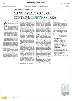
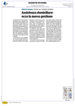
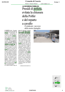
RCHD TECHNICAL MANUAL
INTRODUZIONE
INTRODUCTION
Gentile Cliente,
AERTESI desidera ringraziarla per la scelta dei nostri
prodotti. Le unità di recupero calore RCHD sono state
progettate e realizzate per applicazioni di tipo
residenziale e commerciale e permettono di coniugare
l’esigenza di rinnovo dell’aria con il massimo risparmio
energetico.
Infatti, laddove sia richiesto o previsto il ricambio forzato
dell’aria ambiente, l’unità provvede al trasferimento di
parte del calore tra il flusso di aria esterna usata per il
rinnovo e quello di aria viziata ripresa dall’ambiente ed
inviata all’espulsione, altrimenti perso.
Per loro natura, sono unità che tendono generalmente
ad
integrarsi
ai
tradizionali
sistemi
di
riscaldamento/condizionamento, anche se, corredate
degli opportuni accessori, possono essere impiegate in
forma del tutto autonoma.
Dear Customer,
AERTESI would like to thank you for the choice of our
products. The heat recovery units RCHD are designed
and developed for residential and commercial
applications and allow the room air renewal with the
highest energy saving.
In fact, where the room air renewal is needed, the unit
transfers heat between the room exhaust air and the
fresh air, heat that otherwise would be lost.
These units may be integrated with traditional heating
and cooling systems, but they can operate also alone if
equipped with the proper accessories.
The series, both horizontal and vertical configuration,
consists of ten sizes, and covers 200 ÷ 6800 m3/h
airflow range.
La serie, sia nella configurazione orizzontale che
verticale, si articola su dieci grandezze, per portate
d’aria che vanno da 200 a 6800 m3/h.
-1-
AERTESI S.r.l. Via della Tecnica 6 35026 Conselve (PD) Tel +39 0499501109 Fax +39 0499500823 e-mail: [email protected] web: www.aertesi.com
Rev. 01/2013
RCHD TECHNICAL MANUAL
INDICE
INDEX
SEZIONE 1 – CARATTERISTICHE TECNICHE
1.1 Caratteristiche generali
1.2 Dimensioni d’ingombro
1.3 Dati tecnici e prestazioni
1.4 Livelli sonori
SEZIONE 2 – ACCESSORI
2.1 Batteria interna di riscaldamento SKW
2.2 Riscaldatore elettrico SKE
2.3 Modulo di raffrescamento SAF
2.4 Valvola a 3 vie con attuatore V33
2.5 Sezione esterna di by-pass CDM
2.6 Sezione esterna ad espansione diretta SED
2.7 Sezione di miscela a 3 serrande MS3
2.8 Serranda di regolazione SKR
2.9 Servocomando serranda on/off SSE
2.10 Filtro compatto classe F6 FC6
2.11 Filtro a tasche morbide FT6 – FT7 – FT8
2.12 Sezione esterna di umidificazione /
raffreddamento adiabatico HCP
2.13 Valvola solenoide VSA
2.14 Boccaglio per condotti circolari BCC
2.15 Giunto antivibrante GAT
2.16 Copertura parapioggia TPR
2.17 Cuffia esterna con rete CFA
2.18 Piedini H=180 PD2
2.19 Motori a controllo elettronico DDE
2.20 Pressostato filtri PSTD
2.21 Umidostato ambiente HAS
2.22 Umidostato da canale HCS
2.23 Commutatore di velocità a 3 posizioni CVU
2.24 Pannello di comando PCR
2.25 Termostato antigelo TEG
2.26 Regolazione elettronica LCE
2.27 Regolazione elettronica multifunzione LC2
2.28 Sensore di pressione differenziale DPS
2.29 Sensore di CO2 AQS
2.30 Sistema di controllo qualità dell’aria KAQ
pag. 3
pag. 4
pag. 6
pag. 7
pag. 8
pag. 8
pag. 9
pag. 10
pag. 10
pag. 10
pag. 11
pag. 12
pag. 12
pag. 12
pag. 13
pag. 13
pag. 13
pag. 14
pag. 14
pag. 14
pag. 15
pag. 15
pag. 15
pag. 15
pag. 15
pag. 16
pag. 16
pag. 16
pag. 16
pag. 16
pag. 17
pag. 17
pag. 17
pag. 17
SEZIONE 3 – PRESTAZIONI AERAULICHE
pag. 18
SEZIONE 4 – IDENTIFICAZIONE DELLA MACCHINA
4.1 Identificazione della macchina
pag. 23
-2-
SECTION 1 – TECHNICAL FEATURES
1.1 General features
1.2 Unit dimensions
1.3 Technical data and performances
1.4 Sound level
SECTION 2 – ACCESSORIES
2.1 Internal water heating coil SKW
2.2 Electric heater SKE
2.3 Cooling section SAF
2.4 3 way valve with actuator V33
2.5 External by-pass for free cooling CDM
2.6 External direct expansion coil section SED
2.7 3 dampers mixing box section MS3
2.8 Adjusting damper SKR
2.9 On/off damper actuator SSE
2.10 F6 class compact filter FC6
2.11 Soft bag filter FT6 – FT7 – FT8
2.12 External water humidifier / Adiabatic air cooler
HCP
2.13 Solenoid valve VSA
2.14 Circular duct connection BCC
2.15 Flexible connection GAT
2.16 Roof cover TPR
2.17 External hood CFA
2.18 Supports H=180 PD2
2.19 Inverter driven fan motors DDE
2.20 Air filter pressure switch PSTD
2.21 Room hygrostat HAS
2.22 Ductable hygrostat HCS
2.23 3 step fan speed control CVU
2.24 Control panel PCR
2.25 Antifreeze thermostat TEG
2.26 Electronico control LCE
2.27 Multifunction electronic control LC2
2.28 Differential pressure transducer DPS
2.29 Ductable CO2 transducer AQS
2.30 Air quality control system KAQ
page 3
page 4
page 6
page 7
page 8
page 8
page 9
page 10
page 10
page 10
page 11
page 12
page 12
page 12
page 13
page 13
page 13
page 14
page 14
page 14
page 15
page 15
page 15
page 15
page 15
page 16
page 16
page 16
page 16
page 16
page 17
page 17
page 17
page 17
SECTION 3 – AIR PERFORMANCES
page 18
SECTION 4 – UNIT IDENTIFICATION
4.1 Unit identification
AERTESI S.r.l. Via della Tecnica 6 35026 Conselve (PD) Tel +39 0499501109 Fax +39 0499500823 e-mail: [email protected] web: www.aertesi.com
page 23
Rev. 01/2013
RCHD TECHNICAL MANUAL
SEZIONE 1 – CARATTERISTICHE TECNICHE
SECTION 1 – TECHNICAL FEATURES
1.1 CARATTERISTICHE GENERALI
1.1 GENERAL FEATURES
Telaio portante in lamiera zincata e preverniciata
Pannelli di tamponamento in lamiera zincata e preverniciata
esternamente RAL 9002, zincata internamente,
completamente amovibili
Isolamento termoacustico con spessore 10 mm (per le
taglie da 03 a 10) e 20 mm (per le taglie da 14 a 60) in lana
minerale
Recuperatore di calore statico ad alta efficienza del tipo
aria-aria a flussi in controcorrente con piastre di scambio in
alluminio dotate di sigillatura supplementare; vasca di
raccolta del condensato in alluminio, con scarico rivolto
verso il basso ½” GAS femmina
Filtri a celle sintetiche in classe di efficienza G4 su ripresa
ambiente e su presa aria esterna, estraibili inferiormente o
lateralmente
Ventilatori centrifughi a pale avanti a doppia aspirazione
direttamente accoppiati a motori muti-velocità
Morsettiera esterna con scheda relè per facilitare i
collegamenti elettrici ed il controllo dei ventilatori
-3-
Precoated structural frame
Fully removable sandwich panels (precoated galvanized
steel outside RAL 9002, galvanized steel inside)
Thermal and acoustic insulation; thickness 10 mm (for sizes
from 03 to 10) and 20 mm (for sizes from 14 to 60) of
mineral wool
High efficiency counterflow heat recovery, aluminum heat
exchanger plates with supplementary sealing; aluminum
drain pan, fitted with ½” GAS female threaded bottom outlet
G4 efficiency class synthetic cell filter, placed on suction
sections and on fresh air side, easily removable from side
or bottom
Direct driven double inlet forward curved fans, coupled with
multispeed motor
External terminal block with a relay board to aid the
electrical connection and fan speed control
AERTESI S.r.l. Via della Tecnica 6 35026 Conselve (PD) Tel +39 0499501109 Fax +39 0499500823 e-mail: [email protected] web: www.aertesi.com
Rev. 01/2013
RCHD TECHNICAL MANUAL
1.2 DIMENSIONI D’INGOMBRO
-4-
1.2 UNIT DIMENSIONS
AERTESI S.r.l. Via della Tecnica 6 35026 Conselve (PD) Tel +39 0499501109 Fax +39 0499500823 e-mail: [email protected] web: www.aertesi.com
Rev. 01/2013
RCHD TECHNICAL MANUAL
Model
290
550
1000
1400
1900
2500
3200
4000
5000
6000
A (mm)
990
990
1150
1350
1450
1700
1700
1700
1700
1900
B (mm)
750
750
860
900
900
1230
1230
1230
1350
1450
C (mm)
270
270
385
410
470
490
530
630
705
750
D (mm)
-
-
230
230
280
305
305
405
480
530
Ø (inch)
-
-
¾” F
¾” F
¾” F
¾” F
¾” F
¾” F
1” F
1” F
E (mm)
195
195
245
241
241
323
308
308
353 (278)
379 (334)
F (mm)
170
170
238
224
284
290
331
377
427 (353)
419 (379)
G (mm)
197
197
225
241
241
323
323
323
353
379
H (mm)
100
100
218
270
270
270
297
297
297 (339)
350 (403)
H1 (mm)
153
153
267
267
327
347
387
487
555
615
L (mm)
162
162
240
240
240
306
339
339
339 (297)
403 (350)
L1 (mm)
275
275
330
337
337
502
502
502
555
615
M (mm)
- (119)
- (119)
- (81)
- (81)
- (81)
- (131)
- (101)
- (101)
- (101)
- (101)
S (mm)
75
75
75
75
100
150
150
150
175
200
Weight (kg)
39
41
68
91
99
140
155
179
235
273
-5-
AERTESI S.r.l. Via della Tecnica 6 35026 Conselve (PD) Tel +39 0499501109 Fax +39 0499500823 e-mail: [email protected] web: www.aertesi.com
Rev. 01/2013
RCHD TECHNICAL MANUAL
1.3 DATI TECNICI E PRESTAZIONI
Inverno / Winter
Portata aria
Airflow rate
Pressione static utile
External static pressure
Pressione sonora a 1m
Sound pressure level at 1 m
Velocità
vent. / Fan
speed
Max
Med
Min
Max
Med
Min
Max
Med
Min
Corrente max / Max current
Potenza max. assorbita
Max power input
Potenza specifica vent.
Specific fan power
Grado di efficienza (N)
Efficiency grade (N)
Conformità 2009/125/EC
ErP per l’anno
2009/125/EC ErP compliant
for year
Velocità ventilatore
Fan speeds
Polarità
Poles
Grado di protezione min
Min protection degree
Classe di temperatura min
Min temperature class
Alimentazione elettrica
Electrical power supply
Efficienza (1)
Efficiency (1)
Potenza recuperata (1)
Recovery heating capacity
(1)
Temperatura di mandata
(1)
Supply temperature (1)
Classe di efficienza UNI EN
13053
UNI EN 13053 efficiency
class
1.3 TECHNICAL DATA AND PERFORMANCES
290
550
1000
1400
1900
2500
3200
4000
5000
6000
A
300
200
100
163
184
167
51
50
44
1.40
500
300
150
121
136
144
51
47
41
1.40
930
750
600
111
125
90
65
61
58
2.70
1400
1200
850
129
100
91
65
63
61
6.20
1900
1400
1000
125
97
82
58
54
42
7.80
2500
1700
1150
120
56
46
56
51
45
7.60
3200
2600
2100
114
110
49
59
53
51
12.6
4000
3000
120
105
62
55
6.60
5000
4000
99
139
64
59
11.2
6000
5000
188
208
64
62
10.8
kW
0.34
0.34
1.01
1.37
1.80
1.92
3.00
3.78
7.23
7.73
W/(m3/s)
1376
1019
1027
1449
1172
1019
1301
1133
1428
1594
-
37.9
37.9
37.2
37.6
44.8
43.3
42.4
59.8
51
48.5
-
2013
2013
2013
2013
2013
2013
2013
2015
2015
2013
n°
3
3
3
3
3
3
3
2
2
2
n°
2
2
4
4
4
4
4
4
4
4
-
IP 32
IP 32
IP 44
IP 44
IP 20
IP 20
IP 20
IP 55
IP 55
IP 20
-
B
B
F
B
B
B
F
B
F
F
m3/h
Pa
dB(A)
V-Ph-Hz
Max
Med
Min
Max
Med
Min
Max
Med
Min
kW
Max
-
%
°C
230-1-50
400-3+N-50
53.3
55.7
59.6
1.30
0.90
0.50
7.1
7.6
8.5
58.7
62.2
66.8
2.40
1.60
0.80
8.3
9.1
10.1
57.0
58.0
58.8
4.40
3.90
3.50
7.9
8.2
8.3
51.2
52.1
54.1
6.00
5.20
3.80
6.6
6.8
7.3
50.3
52.1
54.0
7.90
6.10
4.50
6.4
6.8
7.3
55.5
57.9
60.3
11.5
8.20
5.80
7.6
8.1
8.7
53.9
55.2
56.6
14.3
11.9
9.90
7.2
7.5
7.8
54.9
56.7
18.2
14.1
7.4
7.9
53.8
55.3
22.4
18.4
7.2
7.5
53.1
54.3
26.5
22.6
7.1
7.3
H5
H4
H4
H5
H5
H5
H5
H5
H5
H5
(1) aria esterna a –5°C 80% UR, aria ambiente a 20°C 50% UR
outside air temperature –5°C 80% RH, room air temperature 20°C 50% RH
-6-
AERTESI S.r.l. Via della Tecnica 6 35026 Conselve (PD) Tel +39 0499501109 Fax +39 0499500823 e-mail: [email protected] web: www.aertesi.com
Rev. 01/2013
RCHD TECHNICAL MANUAL
Estate / Summer
Portata aria
Airflow rate
Efficienza (2)
Efficiency (2)
Potenza recuperate (2)
Recovery cooling capacity
(2)
Temperatura mandata (2)
Supply temperature (2)
Velocità
vent. / Fan
speed
Max
Med
Min
Max
Med
Min
Max
Med
Min
Max
Med
Min
m3/h
%
kW
°C
290
550
1000
1400
1900
2500
3200
4000
5000
6000
300
200
100
46.2
48.2
51.4
0.30
0.20
0.10
29.2
29.1
28.9
500
300
150
50.8
53.7
57.5
0.50
0.30
0.20
29.0
28.8
28.5
930
800
710
49.3
50.2
50.9
0.90
0.80
0.70
29.0
29.0
28.9
1300
1200
1000
44.8
45.2
45.6
1.10
1.00
0.90
29.3
29.3
29.3
1900
1400
1000
43.7
45.2
46.8
1.60
1.20
0.90
29.4
29.3
29.2
2500
1700
1150
48.0
50.1
52.1
2.30
1.60
1.10
29.1
29.0
28.9
3200
2600
2100
46.7
47.8
49.0
2.80
2.40
1.90
29.2
29.1
29.1
4000
3000
47.5
49.1
3.60
2.80
29.1
29.1
5000
4000
46.7
47.9
4.40
3.60
29.2
29.1
6000
5000
46.1
47.1
5.20
4.50
29.2
29.2
(2) aria esterna a 32°C 50% UR, aria ambiente a 26°C 50% UR
outside air temperature 32°C 50% RH, room air temperature 26°C 50% RH
1.4 LIVELLI SONORI
1.4 SOUND LEVEL
Nella seguente tabella sono riportati i valori di potenza sonora
(SWL) in banda d’ottava e totali; sono inoltre riportati i valori di
pressione sonora (SPL) a 1m, 5m e 10m in mandata, ripresa
ed all’esterno dell’unità.
The following table shows the sound power level (SWL) per
octave band and total; It also shows the sound pressure level
(SPL) at 1m, 5m and 10m on supply air, return air and outside
the unit
SWL [dB]in banda d’ottava [Hz]
SWL [dB] per octave band [Hz]
Taglia
Size
63
SWL
SPL Mandata
Supply SPL
1m
125 250 500 1000 2000 4000 8000 dB dB(A) dB(A)
SPL Ripresa
Return SPL
SPL Esterno
Outside SPL
5m
10 m
1m
5m
10 m
1m
5m
10 m
dB(A)
dB(A)
dB(A)
dB(A)
dB(A)
dB(A)
dB(A)
dB(A)
290
78.6 79.4 77.6 69.0 70.4 71.4 66.9 62.2
84
77
63
52
46
60
49
43
51
40
34
290
78.6 79.4 77.6 69.0 70.4 71.4 66.9 62.2
84
77
63
52
46
60
49
43
51
40
34
1000
72.4 78.9 75.9 71.1 72.8 73.7 71.7 69.0
83
79
65
53
48
62
50
45
52
40
35
1400
94.1 86.9 92.4 85.6 80.9 81.8 82.7 78.2
98
90
76
64
59
73
61
56
62
50
45
1900
90.7 82.9 90.1 79.4 78.6 79.5 79.3 75.5
94
87
72
61
56
69
58
53
58
47
42
2500
93.1 85.9 87.2 77.4 76.5 76.6 73.8 69.1
95
84
69
58
53
66
55
50
56
45
40
3200 103.4 83.2 88.7 78.6 80.0 79.9 77.6 72.6 104
87
72
61
56
69
58
53
59
48
43
4000
99
91
76
65
60
72
61
56
62
51
46
5000 110.0 89.9 93.6 84.2 84.1 84.5 82.8 78.5 110
92
76
66
61
73
63
58
64
54
49
6000 111.0 90.9 94.6 85.2 85.1 85.5 83.8 79.5 111
93
77
67
62
74
64
59
65
55
50
-7-
95.4 89.0 92.5 87.7 81.5 82.6 83.5 79.0
AERTESI S.r.l. Via della Tecnica 6 35026 Conselve (PD) Tel +39 0499501109 Fax +39 0499500823 e-mail: [email protected] web: www.aertesi.com
Rev. 01/2013
RCHD TECHNICAL MANUAL
SEZIONE 2 – ACCESSORI
SECTION 2 – ACCESSORIES
2.1 BATTERIA INTERNA DI RISCALDAMENTO
SKW
2.1 INTERNAL WATER HEATING COIL
SKW
Inserita a bordo dell’unità nel circuito di immissione dopo il
recuperatore, questa batteria può eseguire il necessario
trattamento di post-riscaldamento per evitare l’immissione in
ambiente a temperatura troppo bassa. Essa non è idonea al
trattamento di raffrescamento (si veda successivo 2.3).
La seguente tabella fornisce le prestazioni in riscaldamento
alle portate d’aria nominali alle condizioni specificate; per
condizioni operative differenti, esse sono ricavabili attraverso
il software di selezione dedicato (si contatti AERTESI ) :
It takes place inside RCHD unit after the heat recovery in the
supply circuit and it is useful as a hot water reheater to avoid
too low supply temperature. It’s not suitable for cooling
working mode (see the following 2.3).
The table as below gives the heater performance at the
nominal airflow rate and at the specified conditions; for
different working conditions and for different airflow rates, the
updated heating performance can be valued by the specific
AERTESI selection software (contact AERTESI Sales
Department) :
Dati tecnici SKW
SKW technical features
Modello /Model
290
1000
1400
1900
2500
3000
4000
5000
6000
9.6
13.9
18.0
26.7
31.0
39.0
46.0
52.8
35.1
36.1
32.9
35.9
33.4
33.6
29.3
28.5
58
56
85
62
86
90
95
111
kPa
15
36
26
21
28
52
22
25
inch
¾”
¾”
¾”
¾”
¾”
¾”
1”
1”
Potenza
Heating capacity
kW
Uscita aria
Outlet temperature
°C
Perdita di carico lato aria
Air pressure drop
Pa
Perdita di carico lato acqua
Water pressure drop
Diametro attacchi
Connection diameter
550
Non disponibile
Not available
Temperatura aria ingresso 8°C, temperatura acqua in/out 70/60°C
Air inlet temperature 8°C,in/out waterr temperature 70/60°C
2.2 RISCALDATORE ELETTRICO
SKE
2.2 ELECTRIC HEATER
SKE
Trova alloggiamento a bordo dell’unità, nel circuito aria
esterna (SKEe) immissione (SKEi) con potenziale funzione di
preriscaldatore (o antigelo) o postriscaldatore od entrambe,
nel circuito aria di ripresa-espulsione con potenziale funzione
di sbrinamento. Essa è costituita da elementi resistivi in grado
di fornire le potenze riportate in tabella; è fornita completa di
relè di comando e termostato di sicurezza, mentre la
protezione della linea deve essere eseguita a cura
dell’installatore.
It takes place inside the unit as preheater (SKEe) or reheater
(SKEi) or both in the fresh air circuit, as defrost system in the
return circuit.
It is made from modular electric heating elements which are
able to supply the power as in the table; it is complete of
control relay and safety thermostat, while power line
protection must be carried out by the installer.
Dati tecnici SKE
SKE technical features
Modello /Model
-8-
290
500
1000
1400
1900
2500
3200
4000
5000
6000
2
4
4.5
6
9
12
12
12
18
24
17.3
17.3
26.0
34.6
9
13
11
13
Potenza
Heating capacity
kW
Alimentazione
Power supply
V-Ph-Hz
Corrente assorbita
Absorbed current
A
8.7
17.4
6.5
8.7
13.0
17.3
Perdita di carico lato aria
Air pressure drop
Pa
5
5
6
6
8
6
230 – 1 – 50
400 – 3 – 50
AERTESI S.r.l. Via della Tecnica 6 35026 Conselve (PD) Tel +39 0499501109 Fax +39 0499500823 e-mail: [email protected] web: www.aertesi.com
Rev. 01/2013
RCHD TECHNICAL MANUAL
2.3 MODULO DI RAFFRESCAMENTO
RISCALDAMENTO ESTERNO
SAF
/
2.3 COOLING HEATING SECTION
SAF
It’s an insulated box with a coil inside and takes place
between the unit and the supply duct, useful as an air cooler,
even suitable as a reheater; the condensate outlet (1/2” GAS
female threaded) is on the bottom through a stainless steel
drain pan..
E’ un involucro termicamente isolato con batteria di scambio
termico da interporre tra l’unità e la canalizzazione di
mandata, idoneo al raffrescamento o riscaldamento; lo scarico
della condensa, ½” GAS femmina, è inferiore.
Modello /Model
290
550
1000
1400
1900
2500
3200
4000
5000
6000
kW
1.5
2.3
4.3
5.6
7.8
12.7
14.8
18.6
21.6
21.9
Uscita aria
Outlet temperature
°C
15.1
16.2
16.4
16.6
17.1
16.0
16.7
16.7
17.4
18.2
Perdita di carico lato aria
Air pressure drop
Pa
44
59
63
72
84
64
85
84
66
69
Perdita di carico lato acqua
Water pressure drop
kPa
3
6
9
4
5
13
18
19
16
15
P
mm
375
430
450
450
615
615
675
725
L
mm
400
400
700
700
700
800
850
900
H
mm
270
385
410
470
490
630
630
755
Diametro attacchi
Connection diameter
inch
¾”
¾”
¾”
¾”
1”
1”
1”
1 ½”
Peso
Weight
kg
9
17
20
21
25
30
40
50
Potenza frigorifera totale
Total cooling capacity
Condizioni aria in ingresso 28°C 60% UR, temperatura acqua in/out 7/12°C, portata aria nominale
Inlet air condition 28°C 60% RH, in/out water temperature 7/12°C, nominal airflow rate
-9-
AERTESI S.r.l. Via della Tecnica 6 35026 Conselve (PD) Tel +39 0499501109 Fax +39 0499500823 e-mail: [email protected] web: www.aertesi.com
Rev. 01/2013
RCHD TECHNICAL MANUAL
2.4 KIT VALVOLA A 3 VIE
V33
2.4 3 WAY VALVE WITH ACTUATOR
V33
Adatto alla regolazione degli accessorio SKW e SAF, il kit è
composto da valvola miscelatrice a 3 vie e servocomando
alimentato a 230V-1ph-50Hz con controllo a 3 punti.
It consists of a 3-way valve with actuator 230V-1ph-50Hz with
3 point modulation, suitable for SKW and SAF accessory.
2.5 SEZIONE ESTERNA DI BY-PASS
CDM
2.5 EXTERNAL BY-PASS FOR FREE COOLING
CDM
Adatta per realizzare un canale di by-pass dello scambiatore
per free cooling (o free heating), la sezione va posta al di
sopra dell’unità. L’accessorio viene fornita completa di
servomotore
on-off
con
ritorno
a
molla
alimentato a 230V-1ph-50Hz
Per le dimensioni si veda il paragrafo 1.2
Suitable to create a duct to by-pass the heat exchanger for
free cooling (or free heating), the section must be mounted on
the top of the unit. The accessory is supplied complete with an
on-off spring back servomotor (power supply 230V-1ph-50HZ)
For dimensions see paragraph 1.2
2.6 SEZIONE ESTERNA AD ESPANSIONE
DIRETTA
SED
2.6 EXTERNAL DIRECT EXPANSION COIL
SECTION
SED
E’ un involucro termicamente isolato con batteria di scambio
termico ad espansione diretta, adatta per l’utilizzo con fluido
refrigerante R410A, da interporre tra l’unità e la
canalizzazione di mandata, idoneo al solo raffrescamento; lo
scarico della condensa, ½” GAS femmina, è inferiore.
It’s an insulated box with a direct expansion coil, suitable for
R410A refrigerant, inside and takes place between the unit
and the supply duct, useful only as an air cooler; the
condensate outlet (1/2” GAS female threaded) is on the
bottom through a stainless steel drain pan.
- 10 -
AERTESI S.r.l. Via della Tecnica 6 35026 Conselve (PD) Tel +39 0499501109 Fax +39 0499500823 e-mail: [email protected] web: www.aertesi.com
Rev. 01/2013
RCHD TECHNICAL MANUAL
Modello /Model
1400
1900
2500
3200
4000
6000
kW
8.4
9.6
12.5
16.4
19.2
24.7
Uscita aria
Outlet temperature
°C
15.6
16.7
16.7
16.8
17.6
18.9
Perdita di carico lato aria
Air pressure drop
Pa
42
48
54
56
80
124
P
mm
450
450
615
615
725
L
mm
700
700
700
800
900
H
mm
410
470
490
630
755
Diametro attacchi
Connection diameter
inch
¾”
¾”
1”
1”
1 ½”
Peso
Weight
kg
20
21
25
30
50
Potenza frigorifera totale
Total cooling capacity
Condizioni aria in ingresso 28°C 60% UR,refrigerante R410A, temperatura evaporazione 7°C, portata aria nominale
Inlet air condition 28°C 60% RH, refrigerant R410A, evaporation temperature 7°C, nominal airflow rate
2.7 SEZIONE DI MISCELA A 3 SERRANDE
MS3
2.7 3 DAMPERS MIXING BOX SECTION
MS3
Può essere utilizzato qualora si rendano necessarie le
funzioni di ricircolo, per esempio, per velocizzare la messa a
regime termico o per sbrinare il pacco recuperatore. Le tre
serrande possono essere comandate ciascuna da proprio
servomotore o da uno unico, previo montaggio di opportuno
leverismo di coniugazione (accessorio LCS).
Questo modulo può esclusivamente interfacciarsi ad unità
base con orientamento A o B.
It can be used when recirculation working mode is needed, for
example, for speeding-up the room temperature or for
defrosting the recovery pack.
Each of the three dampers can be controlled by an own
servocontrol or all the three dampers by one servocontrol via
a lever system (LCS accessory).
This section can match basic unit only on configuration A or B.
Modello /Model
- 11 -
290
L
mm
Peso / Weight
kg
550
Non disponibile
Not available
1000
1400
1900
2500
3200
4000
5000
6000
450
480
480
650
650
650
707
757
47
59
66
90
99
121
139
149
AERTESI S.r.l. Via della Tecnica 6 35026 Conselve (PD) Tel +39 0499501109 Fax +39 0499500823 e-mail: [email protected] web: www.aertesi.com
Rev. 01/2013
RCHD TECHNICAL MANUAL
2.8 SERRANDA DI REGOLAZIONE
SKR
2.8 ADJUSTING DAMPER
SKR
E’ un organo di calibrazione inserito nel circuito aria,
necessario quando l’impianto aeraulico esterno all’unità deve
adattarsi alla prevalenza utile dei ventilatori di mandata e di
ripresa, per raggiungere il punto di funzionamento nominale.
E’ costituita da telaio ed alette contrapposte in alluminio,
dotate di perno per accoppiamento ad eventuale leverismo
manuale o servocomando elettrico.
It is necessary when air duct pressure drops must meet with
external static pressure of supply and return fans. It is made
from aluminium frame and aluminium contrasted paddles,
controlled by handle lever or electrical servocontrol (not
supplied).
Modello /Model
290
550
1000
1400
1900
2500
3200
4000
5000
6000
A
mm
210
210
310
310
410
410
410
510
610
610
B
mm
280
280
330
330
330
500
500
530
600
600
Peso / Weight
kg
2.5
2.5
3.5
3.5
4
5
5
6
7
7
2.9 SERVOSERRANDA ON/OFF
SSE
2.9 ON/OFF DAMPER SERVOCONTROL
SSE
E’ idoneo per comandare elettricamente qualsiasi serranda,
ha alimentazione monofase a 230V-1ph-50Hz ed è del tipo
on/off con ritorno automatico a molla.
It is suitable for damper control; the power supply is 230V1ph-50Hz single phase. It is on/off with automatic spring back.
2.10 FILTRO COMPATTO F6
FC6
2.10 F6 COMPACT FILTER
FC6
Disponibile a partire dal modello 10, può essere montato in
entrambi gli ingressi aria e realizzato in microfibra di vetro, è
impiegato al posto del filtro standard G4, accrescendone
l’efficienza di filtrazione. Nella tabella seguente è indicata la
perdita di carico da considerare
Available from 10 model, can be mounted on both air intakes
and made from glass microfiber, it is used in place of G4
standard filter, to increase filtering efficiency. The following
table show the filter pressure drop
Modello /Model
Perdita di carico / Pressure drop
Pa
1000
1400
1900
2500
3200
4000
5000
6000
26
42
51
43
50
47
38
34
alla portata aria nominale
at nominal airflow rate
- 12 -
AERTESI S.r.l. Via della Tecnica 6 35026 Conselve (PD) Tel +39 0499501109 Fax +39 0499500823 e-mail: [email protected] web: www.aertesi.com
Rev. 01/2013
RCHD TECHNICAL MANUAL
2.11 FILTRO A TASCHE MORBITE
FT6 – FT7 – FT8
2.11 SOFT BAG FILTER
FT6 – FT7 – FT8
Disponibile a partire dal modello 14 nelle efficienze F6 (FT6),
F7 (FT7) o F8 (FT8), esso accresce la capacità filtrante
dell’unità. Realizzato in materiale sintetico, viene inserito a
bordo macchina, nello stesso telaio di contenimento del
prefiltro G4. Nella versione BP non può essere montato
sull’aria di ripresa. Nella tabella seguente è indicata la perdita
di carico da considerare
Available from 14 model as F6 (FT6), F7 (FT7) or F8 (FT8)
efficiency class, it increases the unit filtering capacity. Made
from synthetic material, it is put inside the unit, in the same
frame of the G4 prefilter.
In BP version, this option is not available on return air intake.
The following table show the filter pressure drop.
Modello /Model
Perdita di carico / Pressure drop
1400
1900
2500
3200
4000
5000
6000
FT6
Pa
187
170
162
172
189
175
179
FT7
Pa
212
199
191
197
229
205
185
FT8
Pa
255
239
230
238
260
248
225
alla portata aria nominale
at nominal airflow rate
2.12 UMIDIFICATORE/RAFFREDDATORE
ADIABATICO
HCP
2.12 WATER HUMIDIFIER / ADIABATIC AIR
COOLER
HCP
Sezione che si interfaccia direttamente all’unità oppure
canalizzabile, idonea all’umidificazione invernale dell’aria (se
posta nel circuito di immissione) e/o al preraffreddamento
adiabatico estivo (se posta nel circuito di ripresa), tramite
pacco evaporante in PVC alimentato da acqua di rete, il cui
eccesso è a perdere.
External section connected to the unit directly or by duct,
suitable both as winter humidifier (if put in the supply air
circuit) and/or as summer air cooler (if put in the return air
circuit), by a PVC evaporative pack feeded by not-recycled
water.
Modello /Model
290
550
1000
1400
1900
2500
3200
4000
5000
6000
Saturazione / Sat
%
73
68
68
65
62
64
61
62
61
61
Perdita di carico lato aria
Air pressure drop
Pa
23
58
53
105
166
116
193
167
166
180
Larghezza / Width
mm
375
430
450
450
615
615
675
725
Lunghezza / Lenght
mm
400
400
700
700
700
800
850
900
Altezza / Height
mm
270
385
410
470
490
630
630
755
Diametro attacchi
Connection diameter
inch
Peso
Weight
kg
25
30
40
50
½”
9
17
20
21
Portata aria nominale
Nominal airflow rate
2.13 VALVOLA SOLENOIDE PER HCP
VSA
2.13 SOLENOID VALVE FOR HCP
VSA
Si tratta di una valvola a 2 vie 1/2", alimentazione 230V-1ph50Hz, per la gestione del sistema di umidificazioen HCP.
It consists in a 2 way solenoid valve, supply 230V-1ph-50Hz,
1/2" connections, suitable to fit water humidifier HCP.
- 13 -
AERTESI S.r.l. Via della Tecnica 6 35026 Conselve (PD) Tel +39 0499501109 Fax +39 0499500823 e-mail: [email protected] web: www.aertesi.com
Rev. 01/2013
RCHD TECHNICAL MANUAL
2.14 ATTACCO CIRCOLARE
BCC
2.14 CIRCULAR DUCT CONNECTION
BCC
Permette il collegamento dell’unità a raccordi o condotti
circolari per la distribuzione dell’aria; può essere
indifferentemente impiegato sulle bocche prementi e/o
aspiranti.
It allows the connection between the unit and the air plant
fitted with circular joints or ducts; it can be installed both on
the air inlets and outlets.
Modello /Model
290
550
1000
1400
1900
2500
3200
4000
5000
6000
A
mm
197
224
241
230
323
307
307
354
378
B
mm
356
411
418
440
583
616
616
652
694
C
mm
133
194
208
208
228
250
275
352.5
377.5
D
mm
196
312
312
312
351
396
446
556
626
2.15 GIUNTO ANTIVIBRANTE ESTERNO
GAT
2.15 FLEXIBLE CONNECTION
GAT
Consente la connessione flessibile tra l’unità e le
canalizzazioni dell’aria, al fine di eliminare la trasmissione
delle vibrazioni generate dagli organi mobili della macchina.
Per le dimensioni riferirsi a quelle delle serrande SKR, per il
modello considerato.
It allows the flexible connection between the unit and the air
ducts, to cut off the transmission of the mechanical vibrations
due to the mobile parts of the unit. For the dimensions, see
the SKR dimensions for the considered size.
2.16 COPERTURA PARAPIOGGIA
TPR
2.16 ROOF COVER
TPR
Il tettuccio di protezione, in lamiera preverniciata, è necessario
nel caso in cui per l’unità sia prevista un’installazione
all’aperto in posizione protetta; è comunque raccomandabile,
per quanto possibile, montare l’unità in locali appositi, al
coperto e facilmente accessibili.
The precoated roof cover is to be used when unit is installed
outdoor in a protected position; however, it is recommended to
install the unit in suitable, indoor and easily accessible places
possibly.
- 14 -
AERTESI S.r.l. Via della Tecnica 6 35026 Conselve (PD) Tel +39 0499501109 Fax +39 0499500823 e-mail: [email protected] web: www.aertesi.com
Rev. 01/2013
RCHD TECHNICAL MANUAL
2.17 CUFFIA ESTERNA CON RETE
CFA
2.17 EXTERNAL HOOD
CFA
Permette all’unità di aspirare o espellere direttamente
nell’ambiente (o all’esterno) dove è posizionata, garantendo la
necessaria protezione ed impedendo l’ingresso di corpi
estranei.
It allows the unit to have intakes and exhausts directly in
place, and avoid possible risks of injury and entrance of
anything.
2.18 PIEDINI H=180 mm
PD2
2.18 SUPPORT H=180 mm
PD2
Consiste in 4 piedini di sollevamento dell’unità ad altezza
maggiorata a 180 mm; adatto ad unità orizzontali ed verticali,
in quest’ultime sostituisce i piedini standard di altezza 90 mm.
It consists of 4 supports, height 180 mm, for horizontal and
vertical units, where replaces the standard support of height
90 mm.
2.19 MOTORI A CONTROLLO ELETTRONICO
DDE
2.19 INVERTER DRIVEN FAN MOTORS
DDE
Nel caso in cui l’impianto asservito all’unità richieda la
variazione controllata della portata d’aria di esercizio oppure il
mantenimento della stessa al variare delle perdite di carico dei
circuiti aria, è possibile utilizzare elettroventilatori con motore
dotati di regolazione integrata in frequenza, settati per
funzionamento a velocità variabile tramite segnale 0÷10V.
Questo accessorio è disponibile per tutte le taglie (tranne 03 e
06) e consente, tra l’altro, un sensibile incremento della
pressione utile come indicato nella tabella sottostante.
When controlled changing or automatic preservation of
nominal airflow rate is required while air pressure drops are
changing, it is possible to use fan-motors equipped with
integrated frequency regulation and set for variable speed
mode by 0÷10V control signal.
This option is available on all sizes (but 03 and 06) and gets
further static pressure as shown on the following table
Modello /Model
1000
1400
1900
2500
3200
4000
5000
6000
Corrente massima / Max current
A
12.0
12.6
15.6
15.6
16.0
16.4
11.2
10.8
Massima pressione statica utile */ Max
E.S.P. *
Pa
375
285
335
420
260
285
99
188
Alimentazione / Power supply
V–Ph–Hz
Livello protezione IP / IP protection level
-
230–1–50
IP 44
IP 44
IP 44
IP 44
400–3–50
IP 44
IP 44
IP 55
IP 55
* alla portata aria nominale, senza accessori / at nominal air flow, without any accessory
2.20 PRESSOSTATO FILTRI
PSTD
2.20 AIR FILTER PRESSURE SWITCH
PSTD
E’ adatto al controllo dello stato di intasamento dei filtri aria,
intervenendo su un circuito elettrico al raggiungimento di un
preimpostato valore di pressione differenziale.
It is suitable for control of air filter dirt condition, by acting on
an electrical circuit when set-point pressure value is achieved.
2.21 UMIDOSTATO DA AMBIENTE
HAS
2.21 ROOM HYGROSTAT
HAS
Umidostato per installazione in ambiente, necessario per
poter gestire accessorio HCP per umidificazione dell’aria.
Hygrostat to be placed in the ambient, it allows to manage
humidification system, accessory HCP.
- 15 -
AERTESI S.r.l. Via della Tecnica 6 35026 Conselve (PD) Tel +39 0499501109 Fax +39 0499500823 e-mail: [email protected] web: www.aertesi.com
Rev. 01/2013
RCHD TECHNICAL MANUAL
2.22 UMIDOSTATO DA CANALE
HCS
2.22 DUCTABLE HYGROSTAT
HCS
Umidostato per installazione nel canale di ripresa, necessario
per poter gestire accessorio HCP per umidificazione dell’aria.
Hygrostat to be placed in the return duct, it allows to manage
humidification system, accessory HCP
2.23 COMMUTATORE DI VELOCITA’ A 3
POSIZIONI
CVU
2.23 3 STEP FAN SPEED CONTROL
CVU
Adatto per l’installazione a parete, consente di selezionare
manualmente una delle velocità disponibili dei ventilatori. Sul
pannello sono presenti :
interruttore acceso/spento
commutatore velocità a 3 posizioni
Suitable for wall installation, it allows to select one of the
possible fan speeds.
On the control panel there are :
•
on/off switch
•
3 position speed switch.
2.24 PANNELLO DI COMANDO
PCR
2.24 CONTROL PANEL
PCR
Adatto per l’installazione a parete, consente il controllo on/off
della temperatura ambiente sia in regime estivo che in quello
invernale e la selezione delle velocità dei ventilatori; il sensore
di temperatura può essere eventualmente remotato rispetto
all’ambiente in cui è installato il pannello.
Su di esso sono presenti :
•
interruttore acceso/spento-commutatore E/I
•
commutatore velocità
•
manopola di regolazione della temperatura
•
gestione riscaldatore elettrico
Suitable for wall installation, it allows to control the room
temperature (on/off control) both in summer and winter mode
and to select the fan speed; the temperature sensor can be
eventually far from the wall panel.
2.25 TERMOSTATO ANTIGELO
TEG
2.25 ANTIFREEZE THERMOSTAT
TEG
Può essere utilizzato in tutte le applicazioni in cui è necessario
controllare che la temperatura in un certo punto del sistema
non scenda al di sotto di un valore di guardia prestabilito.
It can be used everywhere temperature must not drop below a
certain fixed safety value..
2.26 REGOLAZIONE ELETTRONICA
LCE
2.26 ELECTRONIC CONTROL
LCE
Adatto per una regolazione dell’unità con sistema di by-pass
per free-cooling / free-heating, consente:
Selezione automatica / manuale delle velocità
Gestione valvola freddo / promiscua
Gestione valvola calda
Gestione resistenza ON-OFF
Post ventilazione
Gestione serranda free-cooling
Gestione allarmi
o Errore sonda
o Surriscaldamento resistenza
o Allarme filtro sporco
Programmazione settimanale
ON-OFF remoto
Display remoto con sensore interno
- 16 -
On the control panel there are :
•
on/off and S/W switch
•
fan speed switch
•
temperature control knob
•
electric heater on/off control
Suitable to control the unit equipped with by-pass
system for free-cooling / free-heating, it allows:
Automatic / Manual 3 speed fan
point cooling / changeover floating valve
point heating floating valve
ON-OFF Electric heater
Post ventilation
Free cooling - Free heating damper
Alarm management and diagnostic
o Sensor failure
o Heater over temperature
o Dirty filter alarm
Clock program management
Remote ON-OFF
Remote display with internal sensor
AERTESI S.r.l. Via della Tecnica 6 35026 Conselve (PD) Tel +39 0499501109 Fax +39 0499500823 e-mail: [email protected] web: www.aertesi.com
Rev. 01/2013
RCHD TECHNICAL MANUAL
2.27 REGOLAZIONE ELETTRONICA
MULTIFUNZIONE
LC2
2.27 MULTIFUNCTION ELECTRONIC CONTROL
LC2
E’ composta sostanzialmente da una parte elettrica che
gestisce la parte di potenza, da un controllo a
microprocessore, da n°03 sonde di temperatura NTC e da un
pannello di comando remoto con display a LCD.
L’involucro di contenimento viene incassato in mezzeria su un
fianco dell’unità.
Consente:
•
Selezione automatica / manuale delle velocità
•
Gestione valvola freddo / promiscua
•
Gestione valvola caldo
•
Gestione pompa freddo/promiscua
•
Gestione pompa caldo
•
Gestione defrost recuperatore
•
Gestione antigelo batteria acqua
•
Gestione resistenza ON-OFF
•
Gestione pressostato filtri
•
Gestione ventilazione con sonda CO2
•
Gestione ventilazione con 1 o 2 sensori di
pressione
•
Gestione serranda free-cooling
•
Gestione camera di miscela
•
Gestione allarmi
•
Post ventilazione
•
Programmazione settimanale
•
ON-OFF remoto
•
Ingresso digitale allarme incendio
•
Cambio modo(caldo/freddo) da ingresso
digitale
•
Termica minima temperatura acqua calda
•
Display remoto con sensore interno
•
BMS protocollo Modbus RS485
It’s composed of an electrical board, a microprocessor
controller, n°03 NTC temperature sensors and a LCD remote
control panel.
The casing containing them is put on a side in place of the
middle panel.
It allows:
•
Automatic / manual fan speed selection
•
point cooling / changeover floating valve
management
•
point heating floating valve management
•
Cold water / change over pump management
•
Hot water pump management
•
Heat exchanger defrost management
•
Water coil antifreeze management
•
On-Off electric heater management
•
Filter pressure switch management
•
Fan management by CO2 sensor
•
Fan management by 1 or 2 pressure sensors
•
By-pass damper management
•
Mixing box management
•
Alarm management and diagnostic
•
Post ventilation
•
Clock program management
•
Remote On-Off
•
Digital input for fire alarm
•
Heating / cooling selection by digital input
•
Hot water minimum thermostat
•
Remote display with internal temperature
sensor
•
BMS Modbus protocol RS485
2.28 SENSORE DI PRESSIONE DIFFERENZIALE
DPS
2.28 DIFFERENTIAL PRESSURE TRANSDUCER
DPS
Sonda di pressione differenziale da canale, permette di
abilitare la regolazione per un funzionamento a pressione
costante (velocità variabile).
A differential pressure sensor that allows the automation
control to work in constant pressure mode, modulating the fan
speed.
2.29 SENSORE DI CO2
AQS
2.29 DUCTABLE CO2 TRANSDUCER
AQS
Sonda di misura del livello di CO2, da canale, permette la
modulazione continua della portata d’aria in funzione del
livello della qualità dell’aria misurato in ripresa.
CO2 sensor, ductable, to be placed on the return duct, it
allows a continuous modulation of the airflow, based on air
quality desired level.
2.30 SISTEMA DI CONTROLLO DI QUALITA’
DELL’ARIA
KAQ
2.30 AIR QUALITY CONTROL SYSTEM
KAQ
Kit per il controllo della ventilazione in funzione della qualità
dell’aria; Il sistema comprende il regolatore il sensore di CO2 e
un trasformatore in bassa tensione.
This KIT allows to control the fan speed for air quality control;
the systems includes the electronic control, the CO2 sensor
and a low voltage tranformer
- 17 -
AERTESI S.r.l. Via della Tecnica 6 35026 Conselve (PD) Tel +39 0499501109 Fax +39 0499500823 e-mail: [email protected] web: www.aertesi.com
Rev. 01/2013
RCHD TECHNICAL MANUAL
SEZIONE 3 – PRESTAZIONI AERAULICHE
SECTION 3 – AIR PERFORMANCES
Le seguenti curve rappresentano, modello per modello, le
pressioni statiche utili erogabili dall’unità base al variare della
portata d’aria.
The following curves are, model by model, the external static
pressure of the basic unit while changing the airflow.
Nel grafico sono anche indicati i valori di pressione sonora ad
1 metro dall’esterno della macchina in dB(A).
In dB(A) are also shown value of sound pressure level at 1 m
from the outside of the unit.
RCHD 290
RCHD 290
RCHD 550
RCHD 550
- 18 -
AERTESI S.r.l. Via della Tecnica 6 35026 Conselve (PD) Tel +39 0499501109 Fax +39 0499500823 e-mail: [email protected] web: www.aertesi.com
Rev. 01/2013
RCHD TECHNICAL MANUAL
RCHD 1000 (a tratteggio versione BP)
RCHD 1000 (dotted line for BP version)
RCHD 1400 (a tratteggio versione BP)
RCHD 1400 (dotted line for BP version)
- 19 -
AERTESI S.r.l. Via della Tecnica 6 35026 Conselve (PD) Tel +39 0499501109 Fax +39 0499500823 e-mail: [email protected] web: www.aertesi.com
Rev. 01/2013
RCHD TECHNICAL MANUAL
RCHD 1900 (a tratteggio versione BP)
RCHD 19 (dotted line for BP version)
RCHD 2500
RCHD 25
- 20 -
AERTESI S.r.l. Via della Tecnica 6 35026 Conselve (PD) Tel +39 0499501109 Fax +39 0499500823 e-mail: [email protected] web: www.aertesi.com
Rev. 01/2013
RCHD TECHNICAL MANUAL
RCHD 3200 (a tratteggio versione BP)
RCHD 3200 (dotted line for BP version)
RCHD 4000 (a tratteggio versione BP)
RCHD 4000 (dotted line for BP version)
- 21 -
AERTESI S.r.l. Via della Tecnica 6 35026 Conselve (PD) Tel +39 0499501109 Fax +39 0499500823 e-mail: [email protected] web: www.aertesi.com
Rev. 01/2013
RCHD TECHNICAL MANUAL
RCHD 5000
RCHD 5000
RCHD 6000 (a tratteggio versione BP)
RCHD 6000 (dotted line for BP version)
- 22 -
AERTESI S.r.l. Via della Tecnica 6 35026 Conselve (PD) Tel +39 0499501109 Fax +39 0499500823 e-mail: [email protected] web: www.aertesi.com
Rev. 01/2013
RCHD TECHNICAL MANUAL
SEZIONE 4 – IDENTIFICAZIONE DELLA
MACCHINA
SECTION 4 – UNIT IDENTIFICATION
4.1 IDENTIFICAZIONE DELLA MACCHINA
4.1 UNIT IDENTIFICATION
Per una corretta individuazione dell’unità è opportuno
specificare tutte le caratteristiche necessarie, indicando prima
il modello base (ad esempio, RCHD/V), poi la taglia (ad
esempio, 25), l’orientamento (ad esempio, tipo A), quindi gli
accessori se presenti (ad esempio, SKR PSTD); pertanto, la
macchina completa sarà definita dalla sigla:
For a precise definition of the unit it is suggested to specify all
necessary data, such as the base model (for example,
RCHD/V), then the size (for example, 25), the orientation (for
example, type A) and the accessories if present (for example,
SKR PSTD); therefore, the complete unit will be defined by:
RCHD/V 25 – Tipo A – SKR PSTD
RCHD/V 25 – Type A – SKR PSTD
Ogni singola unità sarà inoltre caratterizzata da un proprio
codice caratteristico e da un numero di matricola, riprodotti
sulla targhetta CE applicata esternamente.
Besides, each supplied unit is characterized from its own code
and serial number, also present on external CE plate.
- 23 -
AERTESI S.r.l. Via della Tecnica 6 35026 Conselve (PD) Tel +39 0499501109 Fax +39 0499500823 e-mail: [email protected] web: www.aertesi.com
Rev. 01/2013
© Copyright 2026 Paperzz