iWISETM
Models: iWISE 810DTGL
iWISE 815DTGL
iWISE 825DTGL
ENGLISH
Jumper
Function
See Terminal Wiring section, LED Terminal
iWISE 810DTGL/815DTGL/825DTGL detectors are the ultimate motion
detectors for professional installations, incorporating Anti-CloakTM
Technology (ACTTM), adhering to new environmentally friendly guidelines.
iWISE 810DTGL/815DTGL/825DTGL detectors are available in 10m,
15m and 25m models, and include built-in end-of-line (EOL) resistors to
simplify installation.
Installation / Maintenance
1. Mounting - The iWISE 810DTGL/815DTGL/825DTGL can be
PRXQWHGHLWKHURQDÀDWVXUIDFHRURQDZDOOcorner (corner mounting).
Using a suitable tool, open the following knockouts on the detector’s
base (see Figure 1).
Note: Back tamper “Breakable plate” not applicable in this version.
2. To select the correct vertical adjustment position for wide angle lens,
use the scale on the bottom left hand side of the PCB as follows:
Mounting height and scale position based on room size:
Mounting Height
For 810DTGL
L - LONG
S - SHORT
2.1m-2.7m (6'11"-8’10")
10m (33’)
6m (20’)
15m (50’)
6m (20’)
For 815DTGL
MW range adjustment (Figure 4)
1 Over power
2 Under power
3 Correct adjustment
LED
Yellow
Green
For 825DTGL
1.8m-2.0m (5'11"-6’7")
25m (82’)
8m (26’)
Note: For Corridor installations, select position to ”L” and mount the
detector at 2.5m/8’2” height.
A Detector
B Corridor
Note: Reset the detector after each change made to the settings.
5IN1258 D
4. Install the front cover back to its place (in a reverse sequence of
the removal.
5. Perform a Walk test (see Walk Test section).
6. Changing Lenses (see Figure 2).
Terminal Wiring (Figure 5)
U.S. Patent Number:
This product is protected under Patent No. US 7,126,476 B2.
Other patents pending.
RTTE Compliance Statement:
Hereby, RISCO Group declares that this equipment is in compliance
with the essential requirements and other relevant provisions of Directive
1999/5/EC For the CE Declaration of Conformity please refer to our
website: www.riscogroup.com.
EN50131-1 Grade 2
EN50131-2-4 Grade 2
EN50130-5 Class II
&ODUL¿FDWLRQ
EN50130-4
Terminal
- 12 +
ALARM
TAMPER
State
On
Flashing
Description
PIR detection
Trouble in PIR channel
On
MW detection
Flashing
Trouble in MW channel
AT
EE
HU
BE
FI
IE
CY
CZ
FR
IT
LU
SE
BG
MT
SL
RO
NL
ES
TR
DE
LV
PL
SK
CH
DK
GR
LT
ALARM
$WSRZHUXSWKH/('VZLOOÀDVK
consecutively until the end of the warmup period (2-3 minutes).
PT
GB
NO
iWISE 810DTGL/815DTGL/825DTGL applicable countries
(German Version): AT, CZ, SL, DE, TR, RU, EE
iWISE 810DTGL/815DTGL/825DTGL FCC compliance Section
(US version):
FCC Part 15 Note:
This equipment has been tested and found to comply with the limits for a
Class B digital device, pursuant to Part 15 of the FCC rules. These limits
are designed to provide reasonable protection against harmful
interference in a residential installation. This equipment generates, uses
and can radiate radio frequency energy and, if not installed and used in
accordance with the instructions, may cause harmful interference to
radio communications.
However, there is no guarantee that interference will not occur in a
particular installation. If this equipment does cause harmful interference
to radio or television reception, which can be determined by turning the
equipment off and on, the user is encouraged to try to correct the
interference by one or more of the following measures:
5HRULHQWRUUHORFDWHWKHUHFHLYLQJDQWHQQD
,QFUHDVHWKHVHSDUDWLRQEHWZHHQWKHHTXLSPHQWDQGUHFHLYHU
&RQQHFWWKHHTXLSPHQWWRDQRXWOHWRQDFLUFXLWGLIIHUHQWIURPWKDWWR
which the receiver is connected.
&RQVXOWWKHGHDOHURUDQH[SHULHQFHGUDGLR79WHFKQLFLDQ
FCC Warning:
The manufacturer is not responsible for any radio or TV interference
FDXVHGE\XQDXWKRUL]HGPRGL¿FDWLRQVWRWKLVHTXLSPHQW6XFK
PRGL¿FDWLRQVFRXOGYRLGWKHXVHU
VDXWKRULW\WRRSHUDWHWKHHTXLSPHQW
FCC ID: JE4CSMDT
UL Compliance Section:
This product is UL639 listed for Residential and Commercial intrusion
detectors. To comply with UL, note the following:
Ƈ7KHXQLWVDUHLQWHQGHGWREHFRQQHFWHGWRD/LVWHGFRQWUROXQLWRU%XUJODU
alarm power supply with power limited outputs with a voltage range
between 9-16vdc that provides a minimum of four hours standby.
Ƈ7KHXQLWUHOD\VDUHWREHFRQQHFWHGWRUHVLVWLYHORDGVRQO\
Ƈ:DONWHVWVKRXOGEHSHUIRUPHGRQFHD\HDUE\DQLQVWDOOHU
Ƈ)RULQGRRUXVHRQO\
Ƈ7KHUDQJHZDVYHUL¿HGE\8/ZLWKWKH0:VHQVLWLYLW\VHWWR0D[
16mA at 12VDC (Typical)
41mA at 12VDC (max.)
Voltage requirements
Alarm contacts
Tamper contacts
LED operation remote control
Filtering
When an ”Activation Signal”** is applied to the LED
input terminal, all LEDs will be disabled.
Physical
9 -16VDC***
24VDC, 0.1A
24VDC, 0.1A
120 gr. (4.2 oz.)
Selon EN50130-4
Indice de protection:
IP 31/IK 02
Marche (ON)
(Défaut)
Taille du càble à utiliser:
Fil de diamétre au moins 0.5 mm
pour une longueur ne dépassant
pas 300 métres
Important! N'utilisez pas le mode ACT™ dans une
zone en dehors de laquelle le passage d'objets
en mouvement vous paraît logique et attendu, un
couloir par exemple.
127.6 x 64.2 x 46.6 mm
(5 x2.5 x 1.84 in.)
Poids
120g
J4 - Entrée
LED/SET
Les cavaliers J1, J2 permettent de sélectionner
OHVUpVLVWDQFHV(2/¿QGHOLJQH
d'Autoprotection, Alarme et FAULT/AM (1K,
2,2K, 4,7K, 5,6K, 6,8K et 12K) en fonction de la
centrale (cf. Figure 3 ci-dessous).
Suivez les indications du diagramme de connexion
du bloc des terminaux de la Figure 3 pour relier le
détecteur à une zone EOL Double (DEOL).
SW1-1: LED
ON
(Default)
OFF
SW1-2: ACT
ON
OFF
(Default)
Function
Used to determine the operation of the detector’s LEDs
LEDs are enabled, allowing LED control via the LED
input terminal.
LEDs are disabled
Used to determine if ACT mode is enabled or disabled
ACT Enabled
Important: Do not use ACT™ mode if you are
expecting that there will be moving objects outside the
required protected area, a corridor for example.
ACT Disabled.
SW1-3: Green Line
The iWISE 810DTGL/815DTGL/825DTGL includes a Green Line feature
that follows environmental guidelines by avoiding surplus emission.
ON
Green Line feature is enabled: To deactivate the MW
module, the LEDs must be remotely disabled by the
LED terminal.
Note: When ‘Green Line’ is on (Microwave off), the
detector will still activate (PIR only)
Installation
1. Montage – l'iWISE 810DTGL/815DTGL/825DTGL peut être installé
soit sur une surface plane soit en coin (gauche ou droit).
A l’aide d’un outil adequat, ouvrez les pastilles pré-percées
correspondantes sur la báse du dé tecteur (cf. Figure 1).
Remarque:5HWRXUIDOVL¿FDWLRQFDVVDEOHSODTXHSDVDSSOLFDEOH
dans cette version.
3RXUGp¿QLUOHERQUpJODJHYHUWLFDOSRVLWLRQQH]O
DSSDUHLOHQ
/(17,//(*5$1'$1*/(6HUYH]YRXVGHO
pFKHOOH¿JXUDQWVXUOH
côté inférieur gauche de la carte PCB (cf. Figure 6) comme suit:
Hauteur de montage et position selon la taille de la pièce:
Hauteur de montage
Pour 810DTGL
L - LONG
2,1m-2,7m (6'11"-8’10")
SW1-4: Self
Test
Green Line feature in disabled: MW is constantly in
use.
Not applicable in this version.
J1 - Alarm EOL
J2 - Tamper EOL
Jumpers J1 and J2 allow the selection of Tamper
and Alarm resistance (1K, 2.2K, 4.7K, 5.6K, 6.8K)
according to the control panel (see Figure 3).
Follow the terminal block connection diagram in
Figure 3 when connecting the detector to a
Double End Of Line (DEOL) Zone.
J4 - LED/SET
INPUT
Used to determine the polarity of the external input.
See Terminal Wiring section, LED Terminal
C - COURT (SHORT)
10m (33’)
6m (20’)
15m (50’)
6m (20’)
Cf. § Câblage des Terminaux, bornes de connexion
LED (Mise en service).
Test de passage
1. Deux minutes après avoir réalisé la mise sous tension (séquence
G
pFKDXIIHPHQWHIIHFWXH]XQWHVWGHSDVVDJHSRXUYpUL¿HUO
HI¿FDFLWp
du détecteur sur la totalité de la zone à protéger.
2. Assurez-vous d'avoir bien réinstallé le couvercle frontal avant de
mettre le détecteur sous tension (cf. Figure 6).
3. Le potentiomètre situé sur la carte PCB permet de régler la portée de
détection hyperfréquence. Il est important de régler le potentiomètre
sur le niveau le plus bas possible qui fournira cependant une couverture
suf¿VDQWHVXUODWRtalité de la zone à protéger.
Réglage de la portée HF (cf. Figure 4)
1 Trop puissant
2 Pas assez puissant
3 Réglage correct
A Détecteur
B Couloir
MIN MAX
Pour 825DTGL:
$I¿FKDJH/('
LED
1.8m-2,0m (5'11"-6’7")
25m (82’)
8m (26’)
Remarque: Pour les installations en couloir, sélectionnez la position
“L” et appliquez l'option de montage à hauteur de 2,5m/8’2”.
Jaune
Verte
3. Réglez les cavaliers (cf. § Réglage des cavaliers).
4. Replacez le couvercle frontal (en inversant pour cela l'ordre des
étapes de la procédure de retrait).
5. Exécutez un test de passage (cf. § Test de passage).
6. Changement des lentilles (cf. Figure 2).
Câblage des Terminaux (cf. Figure 5)
Terminal
- 12 +
ALARM
Description
Entrée 12VCC
Relais N.F., 24VCC, 0,1A
TAMPER
Relais N.F., 24VCC, 0,1A
Position
Allumée (ON)
6LJQL¿FDWLRQ
Détection IRP
Los detectores iWISE 810DTGL/815DTGL/825DTGL son la última
palabra en detectores de movimiento para instalaciones profesionales,
incorporando la tecnología Anti-Cloak™ (ACT™), adhiriéndose a las
nuevas directrices respetuosas con el medioambiente.
SW1-4: SELF
TEST
(Auto Test)
J4 - LED/SET
INPUT
(ENTRADA
LED/SET)
1. Montaje - El iWISE 810DTGL/815DTGL/825DTGL puede montarse
HQXQDVXSHU¿FLHSODQDRHQXQULQFyQGHSDUHGPRQWDMHHQULQFyQ
Nota: Volver manipulaciones "rompible placa" no se aplica en esta
versión.
2. Para selecccionar la posición correcta de ajuste vertical para lentes
gran angular utilice la escala en el lado izquierdo del PCB, según
se indica:
Altura de montaje y posición de la escala según el tamaño de
la habitación:
Altura de Montaje
Para 810DTGL
2.1m-2.7m (6'11"-8’10")
Para 815DTGL
2.1m-2.7m (6'11"-8’10")
L - LONG
S - SHORT
10m (33’)
6m (20’)
15m (50’)
6m (20’)
25m (50’)
8m (26’)
Para 825DTGL
1.8m-2.0m (5'11"-6’7")
Nota: Para instalaciones de Pasillo, seleccione la posición “L” e
instale a 2.5m/8’2” de altura.
&RQ¿JXUHORVSXHQWHVYpDVHODVHFFLyQ&RQ¿JXUDFLyQGH3XHQWHV
Nota: Reinicie el detector después de que se haga un cambio en las
FRQ¿JXUDFLRQHV
4. Coloque de nuevo la tapa delantera en su lugar (de modo inverso
al de retirarla)
5. Realice una prueba de Movimiento (véase la sección Prueba de
Movimiento).
6. Cambiando las Lentes (ver Figura 2).
Terminal
Descripción
- 12 +
Entrada de 12VCC
ALARM
Relé N.C.
Conmutador del Tamper N.C.
Panne de canal IRP
Allumée (ON)
Détection HF (hyperfréquence)
FAULT/AM No se aplica en esta versión.
(Fallo/AM)
Clignotante
Panne de canal HF
Allumée (ON)
Indique une ALARME
Clignotante
(l'une après
l'autre)
Lors de la mise sous tension, les
diodes LED clignotent de manière
ininterrompue, l'une après l'autre,
MXVTX
jOD¿QGHODVpTXHQFH
d'échauffement (2 à 3 minutes).
La característica Green Line está deshabilitada: el
MW está constantemente en uso
Usado para testar las tecnologías de detección.
Los puentes J1 y J2 permiten la selección de la
resistencia del Tamper y de la Alarma (1K, 2.2K,
4.7K, 5.6K, 6.8K) según el panel de control
Siga el diagrama de conexión del bloque de
terminales de la Figura 3 cuando conecte el
detector a una Zona de Doble Fin-de-Línea
(DEOL).
LED
Control remoto del funcionamiento del LED
Cuando se aplica una ”Señal de Activación”** al terminal
de entrada del LED, se desactivan todos los LEDs.
Los LEDs se activan si no hay nada conectado (a menos
que el puente del LED esté en OFF) o se aplican 0V/12V
(según la posición del Puente LED/SETInput, 12V ó 0V)
**Señal de ActivaciónSi se aplican 12VCC, y el puente (jumper) LED/SET INPUT está en la
posición 12V
-O-
Usado para determinar la polaridad de la entrada
externa.
Véase la sección Cableado del Terminal, Terminal
LED
8VDQGRXQDKHUUDPLHQWDDSURSLDGDDEUDORVVLJXLHQWHVDJXMHURV
pre-marcados en la base del detector (ver Figura 1).
Clignotante
Rouge
La característica Green Line está habilitada: Para
desactivar el módulo de MW, los LEDs deben
deshabilitarse remotamente mediante el terminal LED.
Véase la sección Cableado del Terminal, Terminal
LED
Instalación / Mantenimiento
TAMPER
Toutes
diodes LED
ACT Deshabilitado.
ESPAÑOL
Cableado del Terminal (ver Figura 5)
Pour 815DTGL
2,1m-2,7m (6'11"-8’10")
OFF
(Default)
Cf. § Câblage des Terminaux, bornes de connexion
LED (Mise en service).
Les détecteurs iWISE 810DTGL/815DTGL/825DTGL sont les tout
derniers modèles de détecteurs de mouvement conçus pour
établissements professionnels. Ils intègrent la technologie de
l'Anti-Cloak™ (ACT™), répondant aux nouvelles directives de
protection de l'environnement.
Disponibles en modèles 10m, 15m et 25m, les détecteurs iWISE
810DTGL/815DTGL/825DTGLcomprennent des résistances de Fin
de ligne (EOL = end-of-line) intégrées qui facilitent l'installation.
ACT Habilitado
Importante: No use el modo ACT™ si usted espera
que haya objetos en movimiento fuera del área
protegida requerida, p.ej. un pasillo.
J1 - Alarm EOL
J2 - Tamper EOL
EOL (Fin de Línea)
Détermine la polarité de l'entrée externe.
Jumper Settings
Jumper
2UJDQLVPHGHFHUWL¿FDWLRQ
Los detectores iWISE 810DTGL/815DTGL/825DTGL están disponibles
en versiones de 10m, 15m y 25m, e incluyen resistencias incorporadas
GH¿QDOGHOtQHD(2/SDUDVLPSOL¿FDUODLQVWDODFLyQ
Non applicable dans cette version.
J1 - Alarm EOL
J2 - Tamper EOL
OFF
(Predeterm.)
AFNOR CERTIFICATION: 11 rue Francis de Pressensé
93571 LA PLAINE SAINT-DENIS Cedex, http://www.marque-nf.com
CNPP: BP 2265, 27950 ST MARCEL, http://www.cnpp.com
Green Line désactivé (OFF): le canal HF est
constamment activé.
Arrêt (OFF)
(Défaut)
Los LEDs están deshabilitados.
Usado para determinar si el modo ACT está habilitado
o deshabilitado
NOTA: Cuando ‘Green Line’ está activado (MW
desactivado), el detector aún se activará (sólo PIR).
Dimensions
"Green Line" activée: Pour désactiver le module HF
pendant les périodes d'inactivité, les indicateurs LED
doivent être désactivés à distance.
Los LEDs están habilitados, permitiendo el control del
LED a través del terminal de entrada del LED
El iWISE 810DTGL/815DTGL/825DTGL incluye una característica
Green Line que sigue las directivas medioambientales evitando un
exceso de emisión.
Protection anti-lumière blanche
Physiques
SW1-3: Green Line
L'iWISE 810DTGL/815DTGL/825DTGL comprend une caractéristique
‘Green Line’, concept qui permet aux détecteurs de respecter les
directives environnementales en évitant les émissions excessives.
Función
Usado para determinar el funcionamiento de los LEDs
del detector.
SW1-3: Green Line
ON
Filtrage
ACT activé.
ACT désactivé.
OFF
(Predeterm.)
Optiques
'p¿QLWVLOHPRGH$&7HVWDFWLYpRXQRQ
Arrêt (OFF)
(Défaut)
SW1-2: ACT
ON
'p¿QLWOHIRQFWLRQQHPHQWGHVLQGLFDWHXUV/('GX
détecteur.
Marche (ON)
OFF
0.25 créte à créte
L'activation des indicateurs LED dépend du
paramétrage du contrôle à distance de leur
fonctionnement (cf. § Câblage des Terminaux, borne
de connexion LED).
Les indicateurs LED sont désactivés.
ON
(Predeterm.)
Rétsistance de la boucle de Détection: Etat ouvert: plus que 10
8
Etat fermé: moins que 1 ohm
Ondulations résiduelles maximales
admissibles:
SW1-1: LED
*** Power to be supplied by 5A max. power source using safety
approved wires, with a min Gauge of 20AWG.
FRANÇAIS
24VCC, 0,1A
De -20ºC à 60ºC (-4ºF à 140ºF)
SW1-4:
Weight
Contacts d'autoprotection
De 0ºC à 49ºC (14ºF à 131ºF)
Fonction
SW1-1: LED
Temps minimal de changement d’état: 2.2 seconds
Température de stockage
White Light Protection
127.6 x 64.2 x 46.6 mm (5 x 2.5 x 1.84 in.)
24VCC, 0,1A
Température de fonctionnement
According to EN50130-4
0°C to 49°C (14°F to 131°F)
-20°C to 60°C (-4°F to 140°F)
Size
Contacts d'alarme
Immunité RF
Marche (ON)
Optical
Tension requise
Environnementales
Environmental
RF immunity
Operating temperature
Storage temperature
Puente
Réglage des cavaliers
7HFKQLFDO6SHFL¿FDWLRQ
Electrical
Current consumption
&RQ¿JXUDFLyQGHORV3XHQWHV
14.8 mA à 12VCC (en utilisation
typique)
39.5 mA à 12VCC (max. avec
tous les voyants LED allumés)
9 -16VCC
**Signal d'ActivationSi une tension de 12VCC est appliquée et que le Cavalier d'entrée
LED/SET est en position 12V
-OuSi la Terre (GND) est reliée, le Cavalier d'entrée LED/SET est en
position 0V.
SW1-2: ACT
On
Flashing
(consecutively)
FAULT/AM
**Activation SignalIf 12VDC is applied, and the LED/SET Input Jumper is on 12V position
- Or 0V is applied and LED/SET Input Jumper is on 0V position
Lorsqu'un ”Signal d'Activation”** est appliqué à
l'entrée LED du bloc des terminaux ou bornes de
connexion, les indicateurs LED se désactivent
(cf. aussi l'entrée Test automatique dans le
tableau consacré au Réglage des cavaliers).
Les voyants LED sont activés si rien n'est relié
(sauf si le cavalier LED est éteint (OFF).
Arrêt (OFF)
All LEDs
LED
iWISE 810DTGL/815DTGL/825DTGL applicable countries
(European version):
LED
MIN MAX
Red
Description
12VDC Input
N.C. Relay
N.C. Tamper switch
Not applicable in this version.
LEDs are enabled if nothing is connected (unless LED
jumper is OFF) or 0V/12V is applied (according to the
LED/SET Input Jumper position, 12V or 0V).
Contrôle à distance des indicateurs LED
Consommation électrique
Cavalier
3. Set jumpers (see Jumper Setting section).
© RISCO Group 01/2011
Electriques
1. Two minutes after applying power (warm-up period), walk test the
Detector over the entire protected area to verify proper operation of
the unit (see Figure 6).
LEDs Display
2.1m-2.7m (6'11"-8’10")
Description
Non applicable dans cette version.
Walk Test
2. The MW range can be adjusted by using the potentiometer located
on the PCB. It is important to set the potentiometer to the lowest
possible setting that will still provide enough coverage for the inner
boundary protected area (see Figure 4).
6SpFL¿FDWLRQVWHFKQLTXHV
Terminal
FAULT / AM
Prueba de Movimiento
1. Dos minutos después de la puesta en marcha (periodo de
calentamiento), haga la prueba de movimiento al detector en toda el
iUHDSURWHJLGDSDUDYHUL¿FDUHOFRUUHFWRIXQFLRQDPLHQWRGHODXQLGDG
(véase Figura 6).
2. El rango de MW puede ajustarse mediante el potenciómetro situado
en el PCB (placa de circuito impreso). Es importante ajustar el
SRWHQFLyPHWURDODFRQ¿JXUDFLyQPiVEDMDSRVLEOHTXHD~QSXHGD
SURSRUFLRQDUVX¿FLHQWHFREHUWXUDDOOtPLWHLQWHUQRGHOiUHDSURWHJLGD
Ajuste del Rango de MW (véase Figura 4)
1 Energía excesiva
2 Energía baja
3 Ajuste correcto
A Detector
B Pasillo
MIN MAX
Visualización de los LEDs
LED
Estado
Descripción
Amarillo
Encendido
Parpadeando
Detección PIR
Problema en el canal PIR
Verde
Encendido
Parpadeando
Detección MW
Problema en el canal MW
Rojo
Encendido
ALARMA
Todos los LEDs
Parpadeando
(sucesivamente)
Al poner en marcha, los LEDs
parpadearán consecutivamente
KDVWDHO¿QDOGHOSHULRGRGH
calentamiento (2-3 minutos).
(VSHFL¿FDFLRQHV7pFQLFDV
Eléctricas
Consumo de corriente
16mA a 12VCC (Típico)
41mA a 12VCC (Máx.)
Requisitos de voltaje
Contactos de Alarma
9 -16VCC
24VCC, 0.1A
Contactos de Tamper
Ambientales
24VCC, 0.1A
Inmunidad a RF
Según EN50130-4
Temperatura de funcionamiento
0ºC a 49ºC (14°F a 131°F)
Temperatura de almacenamiento
-20ºC a 60ºC (-4°F a 140°F)
Óptica
Filtrado
Protección contra luz blanca
Físicas
Tamaño
127.6 x 64.2 x 46.6 mm
(5 x 2.5 x 1.84 pul)
Peso
120 gr. (4.2 oz.)
Se aplican 0V y el puente (jumper) LED/SET INPUT está en la posición 0V.
I ponticelli J1 e J2 permettono la selezione dei
valori resistivi da assegnare ai circuiti di Tamper
e di Allarme (1K, 2.2K, 4.7K, 5.6K, 6.8K) in
funzione della centrale d’allarme utilizzata (vedere
la Figura 3 in basso).
Seguire lo schema di collegamento dei morsetti
illustrato in Figura 3 quando si vuole collegare il
sensore ad una centrale d’allarme usando il
doppio bilanciamento resistivo (DEOL).
Nota: Il foro a sfondare per il tamper antirimozione non è applicabile
in questa versione.
2. Per selezionare la posizione corretta della scheda elettronica con la lente
grandangolo montata, usare i riferimenti ( LONG / SHORT) situati nella
parte inferiore sinistra della scheda elettronica seguendo le indicazioni
della tabella di seguito illustrata:
J4- LED/SET
INPUT
Usato per impostare la polarità dei comandi di
attivazione per gli ingressi LED e SET.
Posizionato sul lato 12V richiede come comando di
attivazione una tensione positiva. Fare riferimento
alla sezione relativa il Cablaggio Morsettiera,
morsetto LED.
Altezza di installazione e regolazione scheda elettronica in funzione
dell’area di copertura:
Altezza di installazione
L - LONG
S - SHORT
Per il modello 810DTGL
2.1m - 2.7m
10m
6m
2.1m - 2.7m
Per il modello 825DTGL
15m
6m
1.8m - 2.0m
25m
8m
Posizionato su 0V richiede come comando di
attivazione un riferimento negativo di alimentazione
0V. Fare riferimento alla sezione relativa il Cablaggio
Morsettiera, morsetto LED.
Per il modello 815DTGL
Prova di movimento (Walk Test)
Nota: Per installazioni con Lente Corridoio selezionare sempre la
posizione “L” e montare il rivelatore a 2.5m di altezza.
3. Predisporre i ponticelli (Vedere la sezione relativa).
Nota: $GRJQLPRGL¿FDGHOOHSUHGLVSRVL]LRQLUHJROD]LRQLHffettuare
sempre un reset del rivelatore rimuovendo e applicando tensione.
4. Rimontare il coperchio frontale e stringere la vite di blocco coperchio.
5. Effettuare una prova di copertura (Sezione Prova di movimento).
6. Sostituzione delle Lenti (vedere Figura 2).
Cablaggio Morsettiera (vedere Figura 5)
1. Due o tre minuti dopo aver alimentato il rivelatore (preriscaldamento)
HIIHWWXDUHODSURYDGLFRSHUWXUDGHOO¶DUHDGDSURWHJJHUHYHUL¿FDQGR
la risposta del rivelatore tramite l’accensione dei LED (vedere
Figura 6).
Altura de Montagem
Para 810DTGL
2.1m-2.7m (6'11"-8’10")
2.1m-2.7m (6'11"-8’10")
MIN MAX
10m (33’)
6m (20’)
15m (50’)
6m (20’)
25m (82’)
8m (26’)
Para 825DTGL
1.8m-2.0m (5'11"-6’7")
2. O alcance de Microondas deve ser ajustado usando-se o
potenciômetro, que está localizado no PCB. É importante colocar o
SRWHQFL{PHWURQDFRQ¿JXUDomRPDLVEDL[DSRVVtYHOTXHDLQGDSRVVD
SURSRUFLRQDUVX¿FLHQWHFREHUWXUDSDUDWRGDDiUHDSURWHJLGD
Ajuste do Alcance do Microondas (ver Figura 4)
1 Energia em excesso
2 Energia fraca
3 Ajuste correto
Nota: Para instalações de Corredor, selecione a posição “L” e instale
a 2.5m/8’2” de altura.
LED
Estado
&RQ¿JXUHRVMXPSHUVYHUDVHomR&RQ¿JXUDomRGH-XPSHUV
Amarelo
Aceso
Nota:5HDMXVWHRGHWHFWRUGHSRLVGHFDGDPRGL¿FDomRIHLWDQDV
FRQ¿JXUDo}HV
4. Recoloque a tampa dianteira em seu lugar (na seqüência contrária à
da remoção)
5. Realize uma prova de Caminhada (ver a seção Prova de Caminhada).
6. Troca de Lentes (ver. Figura 2).
Verde
Vermelho
Terminais de Fiação (ver. Figura 5)
Terminal
Descrição
- 12 +
Entrada de 12VDC
ALARME
TAMPER
FALHA/AM
Relé N.F.
Chave do tamper N.F.
Não aplicável nesta versão.
LED
Controle remoto da operação do LED
Quando um “Sinal de Acionamento”** é aplicado ao
terminal de entrada do LED, todos os LEDs serão
desativados .
Os LEDs são ativados se nada estiver conectado (a
menos que o jumper do LED esteja em OFF) ou 0V/12V
for aplicado (segundo a posição do Jumper de Entrada
do LED, 12V ou 0V)
24VDC, 0.1A
&RQ¿JXUDomRGRV-XPSHUV
Imunidade a RF
De acordo com EN50130-4
Temperatura de operação
0°C a 49°C (14°F a 131°F)
Temperatura de armazenamento
-20°C a 60°C (-4°F a 140°F)
Ótica
Filtragem
Proteção contra luz branca
Stato
Descrizione
Giallo
Illuminato
Rilevazione del canale PIR
Jumper
FAULT/AM
Non applicabile in questa versione.
Lampeggiante
Anomalia del canale PIR
SW1-1: LED
Controllo remoto dei LED e funzione GREEN LINE (con
ponticello GREEN LINE inserito)
Usado para determinar a operação dos LEDs do
detector.
LED
Físicas
Tamanho
Illuminato
Rilevazione del canale MW
ON
(Predeterm.)
LEDs estão habilitados, permitindo o controle do LED
através do Terminal de Entrada do LED
Peso
ALLARME
Lampeggiante
All’alimentazione tutti i LED
(consecutivamente) ODPSHJJLDQRLQVHTXHQ]D¿QRDOOD
¿QHGHOSHULRGRGLSUHULVFDOGDPHQWR
(2-3 minuti).
I LED sono abilitati se al morsetto LED non è collegato
niente (a meno che il ponticello LED sia estratto).
**Per Segnale di attivazione si intende quanto segue- Viene applicata una tensione 12 Vcc e il ponticello LED/SET Input è
nella posizione 12v
- Viene applicato un riferimento di alimentazione 0V e il ponticello
LED/SET Input è nella posizione 0V
Predisposizione microinterruttori e ponticelli
Microint./Pontic.
SW1-1: LED
ON
(Default)
OFF
Funzione
Usato per abilitare o disabilitare il funzionamento
dei LED.
OFF
SW1-2: ACT
ON
ON
Assorbimento di corrente
OFF
(Default)
Alimentazione richiesta
Contatti di allarme
Contatti Tamper
da 9V − a 16V−
24V −, 0.1A
24V −, 0.1A
SW1-3: Green Line
Ambientali
I LED sono abilitati ed è possibile anche controllarli
via comando remoto tramite l’ingresso LED.
da 0ºC a 49ºC
Temp. stoccaggio
da -20ºC a 60ºC
I LED sono disabilitati. Non è possibile alcun
controllo remoto.
Ottica
ACT disabilitato.
SW1-3: Green Line
iWISE 810DTGL/815DTGL/825DTGL include la funzione Green Line
FKHHYLWDHPLVVLRQLUDGLRVXSHUÀXHQHOO¶DPELHQWH
ON
La funzione Green Line è abilitata: Per disabilitare
la sezione microonda (MW) va applicato un
comando di attivazione al morsetto LED (0V o 12V
LQIXQ]LRQHGHOODSRODULWjFRQ¿JXUDWDWUDPLWHLO
ponticello LED/SET INPUT). I LED verranno in
questo caso disabilitati. La sezione microonda
viene disabilitata in questo modo solo se al
morsetto SET non viene applicata alcuna tensione.
NOTA: Quando la funzione Green Line è attiva
(Microonda spenta), il rivelatore si attiva usando
la sola sezione ad infrarossi (PIR).
Importante: Não use o modo ACT™ se pensa que
possam existir objetos que se movam fora da área
protegida requerida, um corredor por exemplo.
OFF
(Predeterm.)
Temp. funzionamento
Importante: Non usare la funzione ACT™ se nel
luogo di installazione del rivelatore si prevede
movimento di oggetti al di fuori dell’area protetta
come, ad esempio, il movimento di persone in un
corridoio attiguo.
ACT Habilitado
16mA a 12V − (Nominale)
41mA at 12V − (Massimo)
Conforme a EN50130-4
ACT abilitato
Usado para determinar se o modo ACT está
habilitado ou desativado.
Elettriche
Immunità RF
Usato per abilitare o disabilitare la funzione ACT
LEDs estão desativados.
6SHFL¿FKH7HFQLFKH
Filtro
Dimensioni
Peso
ON
PORTUGUÊS
Os detectores iWISE 810DTGL/815DTGL/825DTGL são a última palavra
HPGHWHFWRUHVGHPRYLPHQWRSDUDLQVWDODo}HVSUR¿VVLRQDLVLQFRUSRUDQGR
a tecnologia Anti-Cloak™ e (ACT™), aderindo às novas normas
amistosas do meio-ambiente.
Os detectores iWISE 810DTGL/815DTGL/825DTGL estão disponíveis
em modelos de 10m, 15m e 25m, e incluem resistências embutidas de
¿PGHOLQKD(2/SDUDVLPSOL¿FDUDLQVWDODomR
Instalação / Manutenção
1. Montagem - O iWISE 810DTGL/815DTGL/825DTGL pode ser montado
numa superfície plana ou num canto da parede (montagem de canto).
8VDQGRXPDIHUUDPHQWDDSURSULDGDDEUDRVVHJXLQWHVIXURV
pré-marcados na base do detector (ver Figura 1).
A característica Green Line está habilitada: Para
desativar o módulo de microondas quando os LED’s
forem desativados remotamente.
NOTA: Quando ‘Green Line’ é ativado (Microondas
Desligado), o detector ainda estará funcionando
(apenas Infravermelhor Passivo).
Protezione contro le luci bianche
127.6 x 64.2 x 46.6 mm
120 gr.
ACT Desativado.
O iWISE DT810DTGL/815DTGL/825DTGL inclui uma característica
Green Line que segue as diretrizes de proteção ao meio ambiente,
evitando a emissão de energia em excesso.
Fisiche
SW1-2: ACT
Função
OFF
(Predeterm.)
A característica Green Line está desativada: o
Microondas está constantemente em uso
SW1-4: Auto
Teste
J1 - Alarm EOL
J2 - Tamper EOL
J4 - ENTRADA
DO LED/SET
Não se aplica a esta versão.
Os jumpers J1 e J2 permitem a seleção da
resistência do Tamper e do Alarme (1K, 2.2K, 4.7K,
5.6K, 6.8K) de acordo com o painel de controle
(ver Figura 3 abaixo).
Siga o diagrama de conexão do bloco de terminais
na Figura 3, ao conectar o detector a uma Zona
de Duplo Fim-de-Linha (DEOL).
Usado para determinar a polaridade da entrada
externa.
Ver a seção Terminais de Fiação, terminai LED.
Nota: Voltar adulterar "quebrável chapa" não se aplica a esta versão.
Ver a seção Terminais de Fiação, terminai LED.
Lens
Back tamper
“Breakable” plate Not applicable in
this version
Figure 4.
MW range adjustment
Figure 3.
Schematic of EOL Resistors
Tamper / Alarm EOL Jumpers
1
B
PANEL DEOL
+12-
2 A
J1 - ALARM EOL JUMPERS
ALARM TAMPER FAULT/AM
3
LED
1K
2.2K
No
Resistor
(Factory Settings)
Ambientais
LED
Illuminato
ALARME
Contatos de Tamper
Interruttore N.C.
Tutti i LED
Aceso
**Sinal de AcionamentoSe 12VDC é aplicado, e o Jumper de Entrada do LED/SET está na
posição 12V
- OU oV é aplicado e o Jumper de Entrada do LED/SET está na posição 12V
Relé N.C.
Rosso
Problema no canal de
Microondas
16mA a 12VDC (Típico)
41mA a 12VDC (Máx.)
9 -16VDC
24VDC, 0.1A
Ingresso di alimentazione 12V
Nota: DI¿QFKpODPLFURRQGDYHQJDGLVDELOLWDWDQRQFLGHYH
essere alcun comando sul morsetto SET.
Detecção no Microondas
Piscando
Requisitos de voltagem
Contatos de alarme
TAMPER
Anomalia del canale MW
Problema no canal de
Infravermelho Passivo
Aceso
Consumo de Corrente
ALARM
Lampeggiante
Piscando
Range
Adjustment Bolt
Thread
Elétricas
- 12 +
Quando viene applicato un ”Segnale di Attivazione”** al
morsetto LED, tutti i LED vengono disabilitati e, se il
ponticello GREEN LINE è INSERITO, la sezione
microonda viene disabilitata.
Descrição
Detecção de Infravermelho
Passivo
(VSHFL¿FDo}HV7pFQLFDV
Descrizione
Verde
MIN MAX
Ao conectar, os LEDs piscarão
Todos os LEDs Piscando
(sucessivamente) FRQVHFXWLYDPHQWHDWpR¿QDOGR
período de aquecimento (2-3
PLQXWRV$R¿QDOGRSHUtRGRGH
aquecimento, o LED VERMELHO
FRQWLQXDUiSLVFDQGRDWpR¿QDO
da iniciação do AM.
Morsetto
LED Stato Descrizione
A Detector
B Corredor
Visualização dos LEDs
Regolazione Portata MW (vedere Figura 4)
A Rivelatore
B Corridoio
C - CURTA
Short Pin
(Facing
upwards)
Para 815DTGL
2. La portata della microonda va regolata tramite l’apposito
potenziometro situato sulla scheda elettronica. Regolare il
potenziometro della microonda al minimo possibile riferito all’area
da proteggere.
1 Regolazione Alta
2 Regolazione Bassa
3 Regolazione corretta
L - LONGA
Cut
Corners
TAMPER
4.7K
5.6K
Figure 5.
Terminal Wiring
6.8K
12VDC
J2 - TAMPER EOL JUMPERS
+ 12 -
ALARM
TAMPER FAULT/AM LED
ALARM
127.6 x 64.2 x 46.6 mm
(5 x 2.5 x 1.84 pol.)
120 gr. (4.2 oz.)
1K
2.2K
No
Resistor
(Factory Settings)
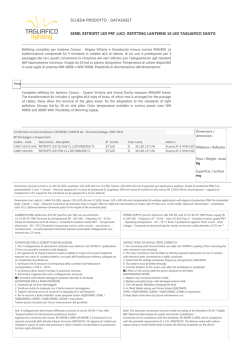
Figure 6.
iWISE 810DTGL/815DTGL/825DTGL
Lenses and Microwave Range
RISCO Group Limited Warranty
5,6&2*URXSDQGLWVVXEVLGLDULHVDQGDI¿OLDWHV6HOOHUZDUUDQWVLWVSURGXFWV
to be free from defects in materials and workmanship under normal use for 24
months from the date of production. Because Seller does not install or connect
the product and because the product may be used in conjunction with products
not manufactured by the Seller, Seller cannot guarantee the performance of
the security system which uses this product. Seller's obligation and liability
under this warranty is expressly limited to repairing and replacing, at Seller's
option, within a reasonable time after the date of delivery, any product not
PHHWLQJWKHVSHFL¿FDWLRQV6HOOHUPDNHVQRRWKHUZDUUDQW\H[SUHVVHGRU
LPSOLHGDQGPDNHVQRZDUUDQW\RIPHUFKDQWDELOLW\RURI¿WQHVVIRUDQ\SDUWLFXODU
purpose.
In no case shall seller be liable for any consequential or incidental damages for
breach of this or any other warranty, expressed or implied, or upon any other
basis of liability whatsoever.
Seller's obligation under this warranty shall not include any transportation
charges or costs of installation or any liability for direct, indirect, or consequential
damages or delay.
Seller does not represent that its product may not be compromised or
circumvented; that the product will prevent any personal injury or property loss
E\EXUJODU\UREEHU\¿UHRURWKHUZLVHRUWKDWWKHSURGXFWZLOOLQDOOFDVHVSURYLGH
adequate warning or protection. Seller, in no event shall be liable for any direct or
indirect damages or any other losses occurred due to any type of tampering,
whether intentional or unintentional such as masking, painting or spraying on the
lenses, mirrors or any other part of the detector. Buyer understands that a properly
installed and maintained alarm may only reduce the risk of burglary, robbery or
¿UHZLWKRXWZDUQLQJEXWLVQRWLQVXUDQFHRUDJXDUDQW\WKDWVXFKHYHQWZLOOQRW
occur or that there will be no personal injury or property loss as a result thereof.
Consequently seller shall have no liability for any personal injury, property
damage or loss based on a claim that the product fails to give warning. However,
if seller is held liable, whether directly or indirectly, for any loss or damage
arising under this limited warranty or otherwise, regardless of cause or origin,
seller's maximum liability shall not exceed the purchase price of the product,
which shall be complete and exclusive remedy against seller.
No employee or representative of Seller is authorized to change this warranty
in any way or grant any other warranty.
WARNING: This product should be tested at least once a week.
RISCO Contacting Info
UK Tel: +44-161-655-5500
E-mail: [email protected]
ITALY Tel: +39-02-66590054
E-mail: [email protected]
SPAIN Tel: +34-91-490-2133
E-mail: [email protected]
FRANCE Tel: +33-164-73-28-50
E-mail: [email protected]
BELGIUM Tel: +32-2522-7622
E-mail: [email protected]
SINGAPORE Tel: + 65-66222388
E-mail: [email protected]
POLAND Tel: +48-22-500-28-40
E-mail: [email protected]
ISRAEL Tel: +972-3-963-7777
E-mail: [email protected]
U.S.A Tel: +1-631-719-4400
E-mail: [email protected]
BRAZIL Tel: +55-11-3661-8767
E-mail: [email protected]
CHINA (Shanghai) Tel: +86-21-52-39-0066
E-mail: [email protected]
CHINA (Shenzhen) Tel: +86-755-82789285
E-mail: [email protected]
4.7K
5.6K
6.8K
iWISE 810DTGL
iWISE 815DTGL
Feet
Feet
Feet
Meters
Feet
RL115D (Wide Angle)
J1 - Alarm EOL
J2 - Tamper EOL
Installazione / Manutenzione
1. Installazione - iWISE 810DTGL/815DTGL/825DTGL può essere
LQVWDOODWRVLDVXGLXQDVXSHU¿FLHSLDQDFKHDGDQJROR
8WLOL]]DQGRXQRVWUXPHQWRDSSURSULDWRDSULUHLIRULDVIRQGDUHGL
seguito elencati, della base del contenitore come illustrato in Figura 1.
Altura de montagem e posição da escala baseada no tamanho
do local:
Sleeve
Meters
Feet
Feet
Meters
Feet
Meters
Feet
Feet
Feet
Meters
Feet
RL15 (Corridor)
iWISE 810DTGL/815DTGL/825DTGL sono disponibili nei modelli 10,
HPHWULHGKDQQROHUHVLVWHQ]HGL¿QHOLQHDLQWHJUDWHQHOFLUFXLWR
SHUVHPSOL¿FDUQHDOPDVVLPRO¶LQVWDOOD]LRQH
Non applicabile in questa versione.
Figure 2.
Lens Replacement
Feet
Meters
Feet
Meters
Feet
iWISE 825DTGL
Feet
30
8
6
RL115C (Curtain)
SW1-4: Self
Test
1. Dois minutos depois de ativar (período de aquecimento), caminhe
SDUDWHVWDUR'HWHFWRUDWUDYpVGHWRGDDiUHDSURWHJLGDSDUDYHUL¿FDU
a correta operação da unidade (ver Figura 6).
RL115D (Wide Angle)
I rivelatori iWISE 810DTGL/815DTGL/825DTGLsono rivelatori di
movimento che integrano le tecnologie più avanzate per le installazioni
professionali. Questi rivelatori includono la tecnologia (ACT™) e la
IXQ]LRQH*UHHQ/LQHSHUHYLWDUHHPLVVLRQLVXSHUÀXHQHOO¶DPELHQWH
Figure 1.
Back cover - Knockouts
Prova de Movimento
RL15 (Corridor)
La funzione Green Line è disabilitata. La sezione a
microonda (MW) è sempre accesa.
OFF
(Default)
2. Para usar a posição correta de ajuste vertical para lentes de ângulo
aberto, use a escala localizada no lado esquerdo inferior do PCB,
como segue:
Feet
RL125H (Wide Angle)
Funzione
20
4
10
2
0
0
Feet
Feet
Meters
Feet
Meters
Feet
4
2
0 0
2
Meters 0
Feet 0
4
20
6
8
Meters 0
Feet 0
Meters
Feet
Feet
10
10
30
RL17 (Corridor)
Microint./Pontic.
ITALIANO
2
4
10
6
20
8
10 12
30
40
2
4
10
6
20
8
10
30
12
40
© Copyright 2026 Paperzz